|
192-037 IBM 5494 Remote Control Unit
IBM 5494 Remote Control Unit Brochure
CO2V4002 5494 Maintenance Information
5494 Remote Control Unit User's Guide Rel. 3.0 (GA27-3960-03, 4th Ed., Nov 1994)
5494 Remote Control Unit Functions Reference Rel. 2.0 (SC30-3533-02, 3rd Ed., Nov 1993)
5494 Remote Control Unit Functions Reference Rel. 3.1 (SC30-3533-04, 5th Ed., Aug 1995)
Documentation sourced from bitsavers.org
5494 Remote Control Unit Planning Guide Rel. 3.2 (GA27-3936-05, 6th Ed., Oct 1996)
5494 Remote Control Unit Quick Reference Rel. 3.2 (GA27-3909-05, 6th Ed., Nov 1996)
5494 Remote Control Unit Users Guide Rel. 3.2 (GA27-3960-05, 6th Ed., Nov 1996)
5494 Remote Control Unit Functions Reference Rel. 3.1 (SC30-3533-04, 5th Ed., Aug 1995)
5494 Remote Control Unit Maintenance Information Rel. 3.2 (SY27-0327-05, 6th Ed., Nov 1996)
MHTML format (doesn't load correctly? use IE). Sourced from archive.org
Configuring 5494 Remote Control Units
Related Redbooks (DEAD)
Remote Control Unit R3.2 Bookshelf (DEAD)
5494 Planar
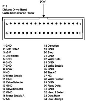
P12 Floppy Controller Header Pinout
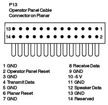
P13 Operator Panel Controller Pinout
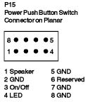
P15 Speaker/Switch Assembly Pinout
System Firmware
ROM Images
Memory (56-pin SIMMs!)
Known Problems
SRC F8F556 (H121724)
5494 Planar 03F0330
![[P]](/other/img/photo.gif "Front")
P1 30-pin header, unknown
P5-8 16-bit MCA slots
P10 56-pin SIMM slot #2
P11 56-pin SIMM slot #1
P12 Floppy Header
P13 Operator Panel
P14 Fan power
P15 Power / LEDs
P16,17 Power Supply Connector
S1 14.318 MHz osc (adapters)
S2 32.00000 MHz osc (CPU)
S3 24.00000 MHz osc
TP1 +5 V test point
TP2 +12 V test point
TP3 -12 V test point
|
U13 Intel 80386SX-16
U14 LM386 Audio op-amp (PC Speaker)?
U17 57F1139
U20 23F8566
U21 Dallas DS1287 RTC/CMOS
U40 27F4620
U53 27F4619
U54 63F7520(ESD) DMA controller
U61 23F9177
U63 02F9624
U77 Firmware ROM 03F0312 Low
U78 Firmware ROM 03F0313 High
U79 82077SL Floppy controller 71F7834
U84 Dallas DS1225AD-170 8Kx8 NVRAM
|
Most of the ASIC/GA are the same with the
Model 55 SX planar and/or various other
PS/2 boards.
P12 Floppy Controller Header Pinout
P13 Operator Panel Controller Pinout
P15 Speaker/Switch Assembly Pinout
System Firmware (POST & BIOS)
Firmware stored in EPROM.
ROM Images
03F0312 / 03F0313 - 28 Jan 1992, rev. 19h, 2x 27C512 (U77 / U78). Bad checksum?
Memory
2MB ECC?? 56-pin SIMM.
53F7913, individual memory modules are 02G2871.
Note: The second stick ("5494 Memory Expansion
Feature") must be installed in order to use the Frame Relay Token-Ring Bridge
feature (and possibly for some other functionality as well).
Known Problems
SRC F8F556 (H121724)
Symptom SRC F8F556
SRC F8F556 is a known problem with the Vimercate produced planars. The way
to identify Vimercate planars is: near the SIMM there is a label with bars. In
this label you can find the P/N 02F9524 and just before it exists a sequence of
letters and numbers. If this sequence starts with "WI" this planar comes from
Vimercate. Everything else comes from Mechanicsburg. Example: WIJA0890187
02F9524 253
Note: SRC F8F556 Can also be caused by a defected
twinaxial adapter card. There is about a 15% probability that the twinax
adapter card is the source of the problem.
Problem Isolation Aids
None.
Fix
Replace the planar. If that does not fix it, replace the twinax adapter
card.
The planar is most likely your problem so replace it first.
|