|
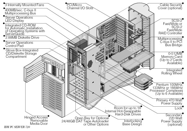
Exploded View
Front Panel
Status LEDs and Information Panel
I²C Bus
Exploded View (codename "Caverun")
Front Panel
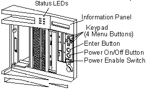
Status LEDs and Information Panel
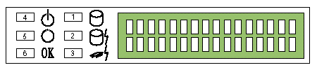
Status LEDs
Green = proper operation, Yellow = alert condition
| LED# |
Definition |
| 1 |
Hard disk drive activity |
| 2 |
DASD error |
| 3 |
Processor Complex Error |
| 4 |
Color green (POWER GOOD) |
| 5 |
Color green (POWER Enabled) |
| 6 |
Color green (All subsystems good) |
Error Codes
General Errors
Corollary Errors (CP,TP,EP,IP,FP,HALT)
PCI Errors (DDDD DD S 0 VVVV IIII)
Liquid Crystal Display
The Liquid Crystal Display (LCD) on the front operator panel contains a
2-line by 16-character LCD (front panel display) driven by the 80C752
microprocessor. The front panel display receives and transmits ASCII
characters. The LCD supports the upper-and lower-case ASCII character set.
Errors detected by the computer might be displayed on the LCD and/or on the
standard display attached to the computer. This is helpful when a display is
not attached to the computer or the attached display is inoperative.
LEDs - System Board and Adapter
LED(s) are located on planar, bridge, processor, and memory card.
| Component |
LED On |
LED Off |
| Planar Slot LEDs: B1 (bridge card slot) |
During / after normal initialization of bridge card |
-SW problem preventing initialization of card
-Defective LED
-Defective bridge card |
M1
(memory card slot) |
During initialization of memory card |
Successful initialization of memory card complete |
M2/P1
(w/ memory card installed) |
During initialization of memory card |
Successful initialization of memory card complete |
M2/P1
(w/ processor card installed) |
During initialization and activity on processor card |
- No activity on processor
- SW problem preventing initialization of card
- Defective LED
- Defective processor card |
P2 thru P6
(with processor card installed) |
During initialization and activity on processor card |
-No activity on processor
- SW problem preventing initialization of card
- Defective LED
- Defective processor card |
| Micro Channel slots |
When computer is powered-off |
When computer is powered-on |
| Bridge card LED |
During / after normal initialization of bridge card |
- SW problem preventing initialization of card
- Defective LED
- Defective bridge card |
| Memory card LED(s) |
During initialization of memory card |
Successful initialization of memory card complete |
| Processor card LED(s) |
During initialization and activity on processor card |
-No activity on processor -SW problem preventing initialization of
card
-Defective LED
-Defective processor card |
I²C Bus (Inter-Integrated Circuit)
The I²C (Inter-Integrated Circuit) bus is a serial bus that is used in
the PC Server 720 to monitor and control several peripheral functions within
the machine. The bus is driven through a VLSI module on the system board. A
service processor on the system board (based on the Intel 83C552
micro-controller) controls and monitors these functions within the machine
through the I²C bus. These include:
- The front panel LCD
- The front panel power controls
- Detecting the setting of the SCSI ID jumper on the hot-swap backplanes
- Reading the voltage and temperature sensors on the planar (viewable using NetFinity)
- Controlling the three fans mounted behind the drive bays.
|