|
Op Panel Upgrade for 9585 K/N
IBM TDB - Information Panel (block diagram of the 95 XP Op Panel)
General Description
95 XP Op Panel Schematic
95 XP Op Panel Connector Pinout
95A Op Panel Schematic
95A Op Panel Connector Pinout
85 Indicator Panel Schematic
85 Indicator Panel Connector Pinout
3511 Indicator Panel Schematic
3511 Indicator Panel Connector Pinout
Power Switch
LED Display Module
Display Module Socket
Op Panel Speaker
Serial Data Link (95A Op Panel Only)
Multimedia Link (95A Op Panel Only)
Op Panel Presence Detect
95 XP Op Panel - Hidden Remote IPL Switch (SW1)
Supposed Origin of Op Panel Board
Cheap Op Panel Lens Redo
Thoughts on Adding a HD LED
Peter's Two-Color LED (Works on early non-shuttered switch only)
Shorney's Shortcut
Button Sizes
Early 95s without Shutter over Power Switch
Free PS/2 Model 95 Power Switch Upgrade
Op Panel Bezels and PCBs
8595 Op Panel
3511 Op Panel
9585 Op Panel
9595A Op Panel
Power Switch Test / Jump Start
Register Information
LED Panel Driver Programs
Odd LED Behavior
8 "Lights" on Op Panel
General Description
Planar provides a 34-pin (2x17) Berg connector to the operator panel. A
matching connector can be found on the panel itself. The panel consists of:
Model 95 XP
Model 95A
Model 85
3511 Enclosure
The original Model 85 "X" planar supports
the 95(A) Op Panel with the LED display out-of-the-box,
no modifications
are required.
The newer 85 "K/N" planar still has a
provision for the Op Panel support logic, however the circuitry is not
populated - see HERE for info on how to
re-enable this feature.
95 XP Op Panel Schematic
ASSY FRU P/N 92F1319, PCB FRU P/N 33F8434, PCB P/N 33F5412
No active components aside from the two LED display units and the Power Good LED.
SW1 enables/disables the "Remote Power-ON" feature.
95 XP Op Panel Connector Pinout
| Pin | Description |
Pin | Description |
| 1 | -Power-ON Request |
2 | -Power Good |
| 3 | Data 0 |
4 | Hardfile LED* |
| 5 | Data 1 |
6 | -Unattended (?) * |
| 7 | Data 2 |
8 | Ground |
| 9 | Data 3 |
10 | Ground |
| 11 | Data 4 |
12 | Ground |
| 13 | Data 5 |
14 | Ground |
| 15 | Data 6 |
16 | Ground |
| 17 | Address 0 |
18 | Ground |
| 19 | Address 1 |
20 | Ground |
| 21 | -Write LED (high) |
22 | Ground |
| 23 | -Write LED (low) |
24 | Ground |
| 25 | +5 V |
26 | Ground |
| 27 | +5 V |
28 | Ground |
| 29 | -Remote Power-ON Request |
30 | -Read LED (all) (?)** |
| 31 | +5 V |
32 | Ground |
| 33 | Speaker Data |
34 | Ground |
(?) - needs confirmation
* - signal not used by the 95 XP Op Panel Board
** - signal grounded on the 95 XP Op Panel Board
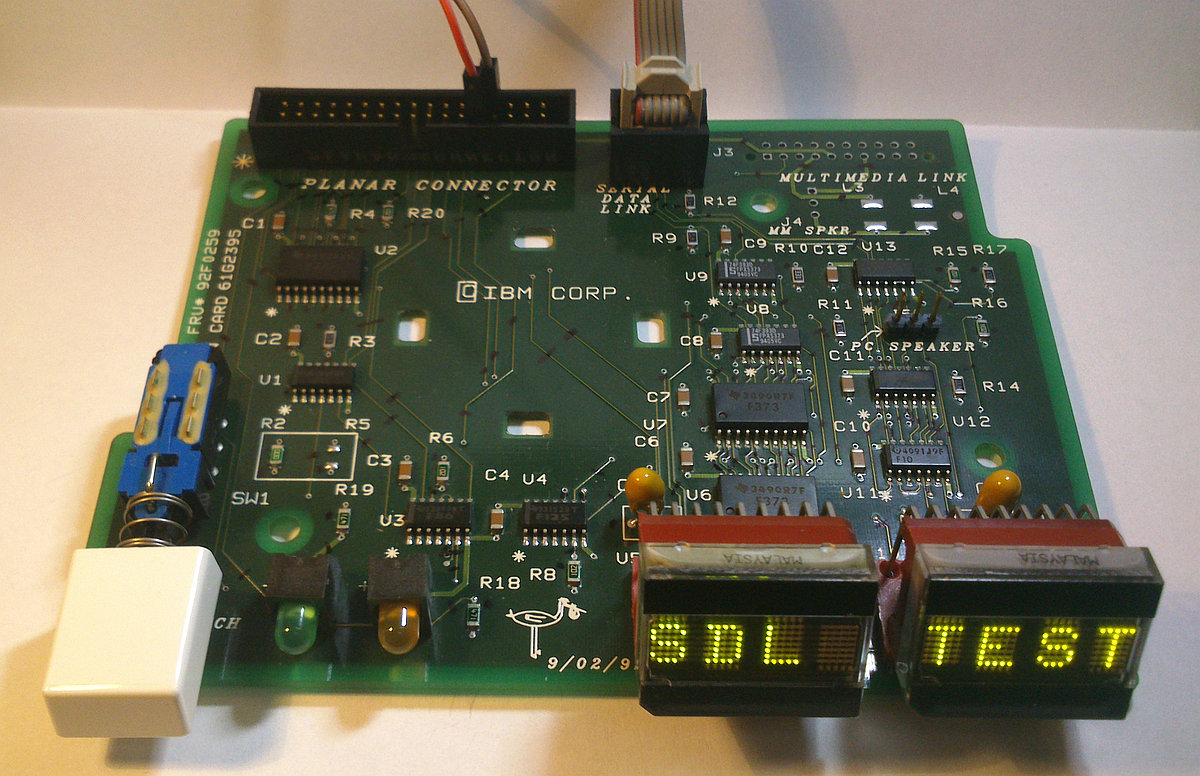
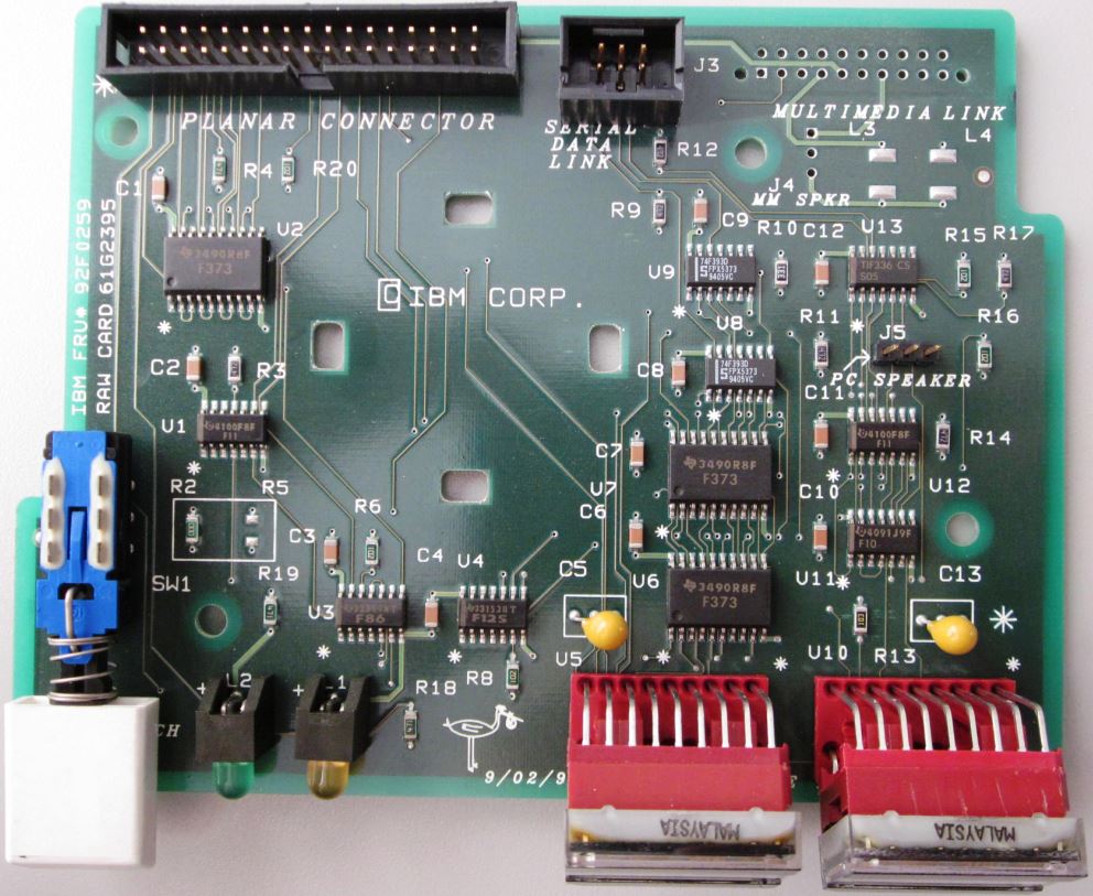
95A Op Panel Schematic
ASSY FRU P/N 61G2393, PCB FRU P/N 92F0259, PCB RAW CARD P/N 61G2395
Active components: two LED display units, Power Good LED, Hard File LED, and
a bunch of 74xx logic ICs. Together the ICs make up a decoder for the
"Serial Data Link" interface.
There is also a provision for something called "Multimedia Link".
R2 is a zero-ohm SMD resistor "jumper". R3 would be another one, but it's
not populated. These jumpers change behavior of the "-Remote Power-ON Request"
signal (J1 pin 29) in regard to the power switch (SW1).
95A Op Panel Connector Pinout
(source)
| Pin | Description |
Pin | Description |
| 1 | -Power-ON Request |
2 | -Power Good |
| 3 | Data 0 |
4 | Hardfile LED |
| 5 | Data 1 |
6 | -Unattended |
| 7 | Data 2 |
8 | Presence Detect 3 |
| 9 | Data 3 |
10 | Presence Detect 2 |
| 11 | Data 4 |
12 | Presence Detect 1 |
| 13 | Data 5 |
14 | Presence Detect 0 |
| 15 | Data 6 |
16 | Ground |
| 17 | Address 0 |
18 | Ground |
| 19 | Address 1 |
20 | Ground |
| 21 | -Write LED (high) |
22 | Ground |
| 23 | -Write LED (low) |
24 | Ground |
| 25 | +5 V (Op Panel) |
26 | Data 7 |
| 27 | +5 V (MM Link) |
28 | Ground |
| 29 | -Remote Power-ON Request |
30 | -Read LED (all) |
| 31 | +5 V (MM Link) |
32 | Speaker Ground |
| 33 | Speaker Data |
34 | Speaker Ground (N/C) |
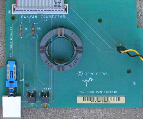
85 Indicator Panel Schematic
ASSY FRU P/N 61G3739, PCB FRU P/N 61G3736, PCB RAW CARD P/N 61G3740
Very simple board. No active components aside from the the Power Good LED
and Hard File LED.
It uses the same connector and pinout as the much fancier Op Panel in Model
95, but most of the pins are unused here.
85 Indicator Panel Connector Pinout
(source)
| Pin | Description |
Pin | Description |
| 1 | -Power-ON Request |
2 | -Power Good |
| 3 | Reserved |
4 | Hardfile LED |
| 5 | Reserved |
6 | -Unattended |
| 7 | Reserved |
8 | Reserved |
| 9 | Reserved |
10 | Reserved |
| 11 | Reserved |
12 | Reserved |
| 13 | Reserved |
14 | Reserved |
| 15 | Reserved |
16 | Ground |
| 17 | Reserved |
18 | Ground |
| 19 | Reserved |
20 | Ground |
| 21 | Reserved |
22 | Ground |
| 23 | Reserved |
24 | Ground |
| 25 | +5 V |
26 | Reserved |
| 27 | +5 V |
28 | Ground |
| 29 | -Remote Power-ON Request* |
30 | Reserved |
| 31 | +5 V |
32 | Speaker Ground |
| 33 | Speaker Data |
34 | Speaker Ground |
* - signal listed as reserved in the Model 85 Technical Reference
Most of the "Reserved" lines are actually connected and wired to support the
9595 Op Panel. Some logic is missing from the planar, but it's possible to
bring the feature back. More info HERE.
3511 Indicator Panel Schematic
ASSY FRU P/N 64F0143, PCB FRU P/N 33F8434, PCB P/N 33F5412
The same PCB as the 95 XP with only the power switch, Power Good LED &
resistor, and a smaller (10-pin) header are populated.
3511 Indicator Panel Connector Pinout
| Pin | Description |
Pin | Description |
| 1 | -Power-ON Request |
2 | -Power Good |
| 3 | N/C |
4 | -Power-ON Request * |
| 5 | N/C |
6 | N/C |
| 7 | Ground * |
8 | Ground |
| 9 | +5 V |
10 | N/C |
* - signal not used by the 3511 Op Panel Board
Power Switch
The switches used on the Op Panel are of the DPDT
(Double-Pole Double-Throw) push-button type (i.e. GC 35-491 or compatible -
diagram,
datasheet).
You can also unsolder the other switch (SW1) on op panels with two switches
and use it as a replacement. It's the same type of switch. Doing so will cost
you the Remote IPL feature.
See how to test the switch / jump start your machine
HERE.
LED Display Module
It's HDLG-2416LED from the HDLX-2416 Series.
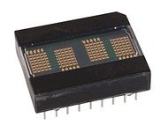
Smart Alphanumeric Display Built-in RAM, ASCII Decoder, and LED Drive
Circuitry Software Controlled Dimming Levels and Blank 128 ASCII Character
Set.
Each module can display 4 characters with 5-by-7 dot pattern.
Display Module Socket
The angled DIP-18 socket was manufactured by
Aries Electronics - you can see their
logo inside the socket cavity (underneath the LED module).
Possibly a customized version of Series 800 Vertisocket to achieve the
desired angle?
Series 800 Vertisocket Datasheet (new)
Series 800 Vertisocket Datasheet (old)
"Consult factory for other display angles"
Op Panel Speaker
95 XP and 95A use the same type of internal speaker: 8 ohms, 0.3 W, 66 mm
outer diameter.
The speaker is marked as: AAP, 66R, 8ohm, 0.3W, PROC
Speaker connector pinout:
| Pin | Description |
| 1 | Speaker Signal (Data) |
| 2 | —* |
| 3 | Speaker Ground |
* - Model 85 Op Panel has another Speaker Ground on pin 2, but this is not
used by the speaker itself.
The speaker is driven by a simple amplifier that is located directly on the
planar board. More info can be found
HERE
(Describes Model 95A, but audio stage in Models 95 XP and 85 is similar).
Serial Data Link (95A Op Panel Only)
Serial Data Link aka Serial Diagnostic Link or SDL is a direct communication
channel between the Processor Complex (Type 4 only) and the Op Panel. It's
explained in greater detail HERE.
Serial Data Link Connector (J2) Pinout:
| Pin | Description |
Pin | Description |
| 1 | Display Sense |
2 | Display Strobe |
| 3 | Display Reset |
4 | — |
| 5 | — |
6 | — |
The SDL port is used by the POST routine to output early diagnostic
information. Go HERE
for more info.
The link is mapped to port E1h. If you want to learn how to use it, visit
THIS page.
The primary benefit of the SDL port is that it can be used to output info to
the Op Panel before the system channel is initialized, and even if the planar
isn't fully operational. Aside from the +5 V power rail, no other connections
between the planar and Op Panel are required for the serial link to operate.
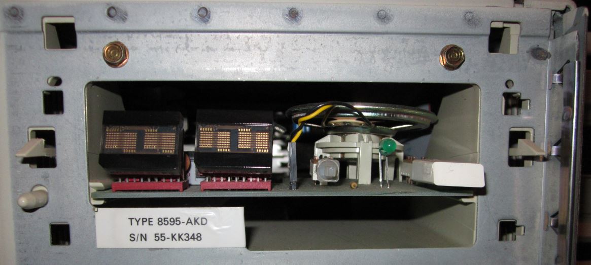
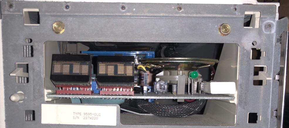
As can be seen here:

The two wires connected to the planar connector supply the panel with power,
pin 25: +5 V (red wire), and pin 28: ground (black wire). The system was
jump-started by shorting pin 1: "-Power-ON Request" to pin 24: ground (this was
done directly on the planar).
Multimedia Link
(95A Op Panel Only)
The 95A Op Panel has a provision for something called "Multimedia Link" but
the related components are not populated. I'm not sure what exactly was this
intended for, but likely for some kind of Ultimedia-like option. Possibly a
separate board that would fit upside-down into the second "rail" set, right
under the main Op Panel PCB. The second board would probably provide a pair of
front panel audio connectors, a volume pot (judging by the matching cutout in
the DASD cage structure), and perhaps an audio amp as well.
Multimedia Link Connector (J3, unpopulated) Pinout:
| Pin | Description |
Pin | Description |
| 1 | Presence Detect 2 |
2 | — |
| 3 | Presence Detect 1 |
4 | — |
| 5 | — |
6 | — |
| 7 | PC Speaker Ground |
8 | — |
| 9 | PC Speaker Data |
10 | +5 V |
| 11 | — |
12 | MM Speaker Ground |
| 13 | MM Speaker Signal |
14 | MM Speaker Ground |
| 15 | — |
16 | +5 V |
| 17 | — |
18 | +5 V |
| 19 | — |
20 | +5 V |
Op Panel Presence Detect (by Tomas Slavotinek)
Before I forget (again...), here is some more info about the Op Panel
presence detect logic of the 9595 2S2P planar.
It's actually even more primitive than I originally thought. There are no
pullups and inverters on the planar. The pins are simply "floating low" (logic
0), and pullup(s) on the Op Panel and Multimedia Panel are used to force the
bits high (logic 1).
This unfortunately means that the 9595 2S2P planar can't differentiate
between the older 9595 Op Panel (the one w/o HD LED) and the 9585 Indicator
Panel. (Pins that are floating low, won't change their state when left floating
or when grounded.)
It can only detect the newer 9595 Op Panel and the unreleased Multimedia
board that would connect to the unpopulated Multimedia Link connector.
The Presence Detect bits 0, 1, and 3 are occupying pins 14, 12, 10, and 8 in
that order. As can be seen HERE.
The four PD bits can be obtained via the Planar POS register cluster in 4
simple steps:
- enable Group 1 Planar registers (set bit 7 of port 94h to 0)
- select the Operator panel information ("Index 7" = 1Dh to port 103h)
- read the Operator panel present info (low 4 bits)
- disable Group 1 Planar regs (set bit 7 of port 94h back to 1)
The mapping is straightforward:
- PD 0 (pin 14) is mapped to the least sig. bit - bit 0 of reg 103h
- PD 1 (pin 12) to 103h bit 1
- PD 2 (pin 10) to 103h bit 2
- PD 3 (pin 8) to 103h bit 3
There are no inverters, so unconnected or grounded pins will show as 0. Pins
tied to +5 V via pullups will show as 1.
Base Op Panel Presence Detect Codes
"0000" - the older 8595 Op Panel
"0000" - the 9585 Indicator Panel
"1000" - the newer 9595 Op Panel (pin 8 tied to 5 V on the panel board)
Multimedia Panel Presence Detect Codes
The newer 95A Op Panel with the Multimedia board will come up as "1xy0"
where "x" depends on the state of the Multimedia Link pin 1, and "y" on the
state of the Multimedia Link pin 3. This gives us 3 other possible values:
"1100" - 95A Op Panel with MML pin 1 tied to 5 V
"1010" - 95A Op Panel with MML pin 3 tied to 5 V
"1110" - 95A Op Panel with MML pins 1 and 3 tied to 5 V
The T4 SurePath BIOS only uses this when Int 15 function CBh ("LED display
- print character at position") is called. It will return 86h - "Not supported"
if the function is called on a 2S2P 9595 that doesn't have the newer Op Panel
connected to it. The older 1S1P planar doesn't have the Presence Detect logic
at all, so the BIOS assumes that the panel is connected and blindly outputs the
data to ports 108 - 10Fh.
The POST routine doesn't actually check the Presence Detect bits it
seems.
Note: One could use the MML pins 1 and 3 as a
cheap GPIO ports... You would have to poll it, and it's just GPI without the O
part.
Debugging comes to mind as one potential use. It may be useful for our BIOS
experiments - to switch between two different code paths or whatever.
Devkits/devboards often have a set of GPIO ports (sometimes hardwired to
switches and LEDs) for this very purpose.
95 XP Op Panel - Hidden Remote IPL Switch (SW1)
What's the switch SW1 for on the op panel PCB?
Tom says:
The SW1 switch is normally hidden behind the Op Panel Bezel.
Contrary to what has been said about it not having any
function in the Model 95, based on its wiring and some testing I have
determined that it enables/disables the "Remote Power-ON" feature.
This allows the system unit to be turned on and off from an
external source - via the J4
pin header on the planar board. For this to work the hidden SW1 switch must
be pressed down, and then it's possible to power the system on by grounding pin
2 of J4, and power it off again by removing this connection. The system will
power down only if the main power switch (SW2) remained in the OFF
position.
The J4 connection would be realized using an externally powered
electronic switch - relay, semiconductor etc. The control signal could be then
supplied from a device connected to a telephone line or some other source.
Ed. Now we know its real name -
Remote Initial Program Load (IPL) Switch (source).
Supposed Origin of Op Panel Board
From Peter:
Back in 1991 (or around) when there were technical trainings on
the 8595s held at IBM someone asked the very same question:"What's the second,
hidden switch for?"
The IBM instructor told us, that the panel card has been taken from some
3270 control unit and the second switch was used to set the IPL mode of that
box or to clear audible alarms or such. "It is not used with the PS/2 -
therefore it is hidden behind the bezel." If it *were* used we have had two
switches in the front.
I used to use the second switch a) as a replacement for the power switch,
which tends to wear out after some time or b) modified the card and bezel to
have the switches in parallel, so that you cannot accidentally power down the
server. One needed to pry in a tiny hole to operate the second switch too to
get it shut down...
Tom reacts:
I know, I know, who am I to question Peter's story, but eh, here
we go... First of all, physical design of the board matches the Model 95 system
unit - it fits perfectly to the 5.25" bay, and the LED display sockets are
angled to match the PS/2-styled bezel. Could that be just a coincidence? I
would say no, unless the "Control Unit" it was supposedly designed for, was of
the PS/2 design as well (or perhaps even based on the Model 95 unit). But in
that case why would they populate the extra switch if it was unused? Or were
the panels already assembled and they just had some spare? I find all this
rather strange...
Based on these observations and my experience, I would say that it was
designed specifically for the Model 95 line, and the switch was either intended
to be hidden - for "operator's eyes and hands only" (you have to unlock and
remove the front bezel to access it, but you don't have to poke inside the
machine itself to do so), and/or it was exposed only on some special bid 95s...
After all the *later* 8595 bezel has a
sub-assembly with a provision for the second switch! It would make no sense to
design and add that part for the revised bezel, if the switch served no
purpose, you would just stop populating it...
Ed. Some IBM patents show the DASD cage with an
early 8595 dual-button Op Panel bezel installed
(i.e. EP0426330B1),
supporting the above explanation:
Ed. Tom: As I have discovered the switch
actually *does* serve a purpose in the Model 95 - it
enables the "Remote Power-ON" feature.
Cheap Op Panel Lens Redo
From Tony Ingenoso:
Tired of the scuffed up scratched LED display panel on
your M95? Would you like it to look as if it were new again?
Here's how -- it takes about 1 minute and makes all the difference in the
world from an aesthetic point of view.
- Remove the bezel containing the LED panel cover.
- Pop the scratched up plastic cover off.
- Look at the locking tabs on the sides - one is a tad wider than the
other.
- Using an X-acto, benchtop belt sander, whatever... make both tabs
the same depth.
- Reinstall modified LED cover with the scratched side facing inwards.
- Voila - your LED panel looks like new and doesn't have any unsightly
scuffs or scratches on it.
Thoughts on Adding a HD LED
I am thinking of using 2 colored LED, and replace the power on LED.
From Peter:
Err... that won't work that easy - you will have to rework the
thing a bit more. The Power LED has +5 V as common and GND over resistor, while
the HD-LED signal supplies +5 V activity signal and common GND... except you
have a LED with 4 wires (2 separated LEDs in one unit).
From Jim Shorney:
And I found this out, too. Although the idea is still kicking
around in the back of my mind, behind some other distractions from down
south...
It should certainly be possible to wire in a simple switching circuit with
an NPN transistor on the HD LED to take care of the difference and allow use of
a common-anode bicolor LED, providing the +5 can source a few extra milliamps.
I haven't figured out (yet) if this comes from hard power or is a signal output
from the PS/planar. The other possibility is to use a common-cathode LED and
share the resistor for the power LED, but I'm not sure how well this would
work. LED's are diodes, after all, so the two sources would be isolated from
each other (in theory), but I'm not sure what this would do to the brightness
of the LED's. I may play around with these ideas in the future, but I wanted to
keep the initial mod as simple as possible for those who might be comfortable
with a soldering iron but don't possess sufficient knowledge to handle wiring
up transistors and such.
From Peter:
About the HD-bicolor LED: I still think it is no good idea. The
difference in the color change is... well... hard to see while the green power
part is permanently on. This could work however if you have a "common cathode"
LED and replace the resistor on the PCB with a small 2-transistor 10 mA
constant current circuit. In this case the pin 4 (HD-LED) could be fed directly
to the anode of the red LED part and the +5 V DC (Power) to the green LED part
and the two LEDs share the common GND and the current limiter.
*But* the visibility is still bad. What you need were a "NAND" function that
switches off the green power LED when the red HD LED comes on... that would
make the color either green *or* red but not a diffuse orange when both come
on.
To simplify the circuit you only need to check the HD signal. As long as it
is low the green LED part is on (if there were no power it were dark anyway)
and once the HD signal pin comes "high" the red LED comes on and the green is
switched off... In this case you could even use a "common cathode" bi-color
LED, which are more familiar than "common anode" types IIRC and keep the
existing current limiting resistor on the PCB.
Still too complicated I think. Faster and -to my opinion- better
results are obtained with installing a bright red LED behind the LED
"window"...
From Peter:
> I thought of that as well. But, as you say, it is starting to
get complicated. I'm perfectly capable of whipping something like that up, but
not sure that I want to go to the trouble. I'm trying to stick to something
that just about anyone can whip up.
Currently I have broken down the "logic" to 2 additional resistors
and a PNP-transistor :-) I'll try out if that works on Thursday maybe and let
you know ... I only need to buy a two-color LED. My first "experimental
assembly" will most likely consist out of two standard-LEDs.
> An LED behind the display window seems to be the best overall
solution.
Yep. The current "implementation" looks pretty cool. I
really wonder why the heck IBM did not include a standard HD-LED
in their darn expensive flagship at that time. I think it might be a reason
that they "recycled" an existing panel-unit from a mainframe controller
- and that simply had no HD...
> One of the triangular ones used in tuning indicators and tape player
directional indicators might look cool.
It sure does - but the rectangular types can be easily fixed with
some superglue on one of the existing LED arrays. Whatever - it is possible to
integrate a LED without damaging the panel bezel... and that counts :-)
> I think I would go with green, myself. And I'm still thinking about
replacing the power LED with a blue one...
Matter of personal taste... and I recently found some "blue LEDs"
which are pretty cheap... and no LEDs at all. They are small lamps (bulbs) with
a blue-colored glass. I think VW used them in earlier years for the "hi-beam"
indicator lamp in their cars. They *look* like LEDs - even have the flattened
side - but unlike to LEDs they work in either polarity. :-)
Peter's Two Color HD LED
Peter's minimalistic "Two-Color LED" Solution.
Principle of Operation
You need to unsolder the existing green LED. The +5 V DC contact needs to be
fed to the above circuit. Only the common cathode of the bi-color LED gets
soldered back in the place where the original LED cathode was.
The two LED-parts use the existing 330 Ohms resistor in common. The PNP
transistor gets minus-potential over the 47K resistor and the green LED lights
up. Even when the HD-pin does not feed minus to the resistor (tri-states) the
GND connection is given over the red LED part and the current-limiting
resistor, so that the green LED will light under any circumstance.
Once the HD-pin gets positive (on HD operation) the positive +5 V pulse will
turn Base of the transistor positive and the green LED goes blank - the red LED
is then on and indicates HD activity.
The type of the PNP-transistor is uncritical. Any type will do. I used this
2SA608 while I had it... In case you want to return to original condition you
only need to remove the circuitry and resolder the single green LED. Pretty
easy, eh?
Note: I found out that my original concept works
only with *one* panel card, which sits in a very early Mod. 8595-AH9 (without
shutter). All my machines have the same panel card that Jim described and to
which he published a "revised version" of my PNP-transistor solution. The two
cards only differ through the position of the current-limiting resistor for the
"power LED" - but that makes a bit difference. Sigh.
Shorney's Shortcut
Parts required
- An LED of the size, shape, and color desired
- One .25 Watt, 330 Ohm resistor
- Two short lengths of small-gauge hookup wire
- Some small heat-shrink tubing
- An IBM Model 95
Tools required
- Soldering iron
- Wire strippers/cutters
Instructions
- Trim the leads of the resistor and the anode lead (the long leg)
of the LED short, and solder one lead of the resistor to the anode of the
LED.
- Solder the two lengths of hookup wire to the other resistor lead
and the cathode (short leg) of the LED.
- Cover the soldered connections with the heat-shrink tubing and, well,
"heat shrink" it.
- Pull your 95 apart, and unplug and remove the operator panel display
PCB (you do know how to do this, right?).
- Secure the LED in your desired mounting location (more on this in
a bit) and cut and strip the two free wire ends to length; the anode lead
(the one coming from the resistor) will be soldered to pin 4 of the ribbon
cable connector, and the cathode lead will be soldered to the frontmost
of the two speaker connector pins (ground). Make your connections
on the bottom of the PCB.
- That's it! Install the PCB back in your Model 95, taking care
not to snag your wires as you slide the PCB back in. Enjoy your hard
disk light!
Now, as to mounting location for the LED... Being into vintage ham radio
gear, I subscribe to the "drill no holes" school of mods. Finding a suitable
location for the LED, without altering or detracting from the aesthetics of the
machine, is the hardest part of this adventure.
My first experiment was to tie the new (red) LED to the existing
power LED with a cable tie, so they are side-by-side. This results in an
interesting green-to-red/green effect when disk access occurs that can be
varied by adjusting the positioning of the LED's behind the bezel, but the
result is not easily discernible from a distance or over a very wide viewing
angle. Another thought that occurs it to somehow fix a square or rectangular
(or some other interesting shape) green LED behind the operator panel window,
either dead center above or below the operator display, or in one of the
corners. I may experiment along those lines when I get my hands on some LED's
that are other than round.
...
I finally got around to trying Peter's nifty circuit for a two-color HDD LED
in a model 95. In the process, I discovered that there are at least two
variations of the info panel PCB. Mine differs from Peter's in the location of
the LED resistor, so I had to change the circuit as shown below:
Circuit function is essentially the same, the change was required because my
board has the 330 ohm on the anode of the power LED instead of the cathode, as
shown in Peter's diagram. The green LED does not fully extinguish in this
configuration because the HD output only seems to source about 3.6 volts under
load, but it is dim enough that the red is clearly visible from an angle or a
distance of a couple of feet (meters?).
That having been said, I also tried a rectangular red LED behind the display
panel on another 95. I must say, I like the way it looks. I fixed it with hot
glue to the bottom of the rightmost operator display LED so it appears directly
below the rightmost character of the display. Now I need to decide which way I
like better...
Button Sizes
The button size between "left-hand" and "right-hand" panels is different -
respectively the *length* of the buttons. Ran into this when I swapped a button
from the 8595 onto the 9585.
Early 95s without Shutter over Power Switch
> Early 8595 have no clear springy cover over the power switch. It's
kinda funky looking having a beige "ring" around the white switch.
Power switch protective shutters became standard in early 1992. 8595 before
then lacked them.
Tony Ingenoso replies:
These are the earliest models - undoubtedly a T1. That "feature"
was rectified fairly quickly when the complaints rolled in from the field.
People who had 'em on the floor were turning them off by mistake thinking they
were reaching for the FDD eject button. This is one of the few truly lame
things about the 95 — because the test labs were complaining about the
same thing fairly early on.
Free PS/2 Model 95 Power Switch Upgrade
(source) (H095521)
As a result of customer requests, the PS/2 Model 95 information/power bezel
has been redesigned. The new design will minimize or eliminate accidental
depression of the power switch when diskettes are inserted or ejected from
drive A:. New Model 95s will ship with this bezel.
The new switch has a clear plastic "trap door" over the power switch. To
enable the switch to be depressed, the "trap door" must be raised by placing a
finger under it and sliding it up. The FRU number of the bezel (33F8423)
remains the same, but will now include the redesigned bezel.
Effective August 20, 1991, and continuing until January 1, 1992, the
redesigned power/information panel is available free of charge in the U.S. to
customers who purchased 8595 systems with the early style panel. Customers may
call toll-free: [number redacted] to have the panel(s) direct-shipped to them
at no charge.
The new power panel is easily installed by the user. Pictorial
removal/replacement instructions are included with the replacement panel along
with a shorter pushbutton and a pushbutton removal tool.
Op Panel Bezels and PCBs
8595 Op Panel
Early 8595 Op Panel Bezel, Front 33F5408
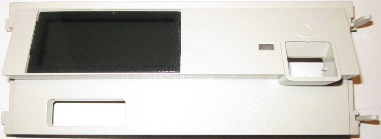
This is one of the earliest Op Panel bezels, note the lack of a shutter over
the Power Switch button, Power Good LED, and the raised edge around the button.
Note that the bezel hooks are on the LEFT and the bezel latches are on the
RIGHT. (Thanks to Jelte for pix)
Early 8595 Op Panel Bezel, Rear 33F5408
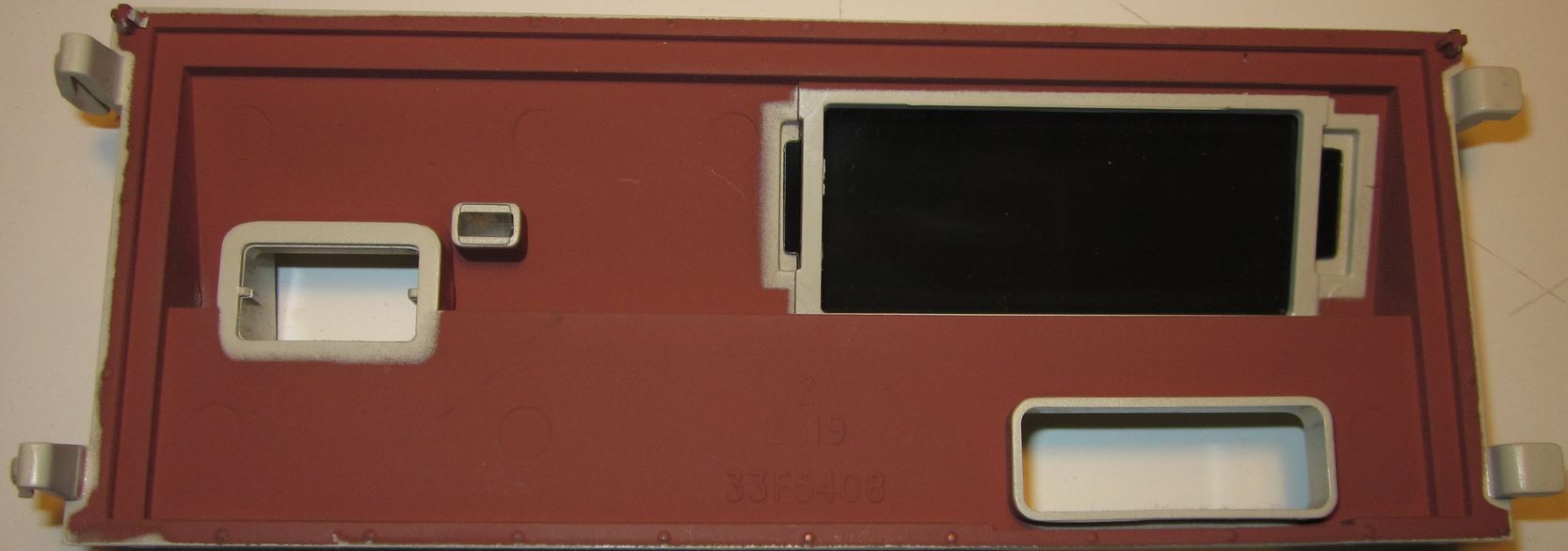
Note the simplicity of this moulded part. See the EMI shielding? That copper
colored coating is replaced on later bezels by the silvery Enshield (which was
probably cheaper as well...). Note the small locating posts at the upper
corners? They fit into holes in the DASD retainer.
Later 8595/9595 Op Panel Bezel, Front
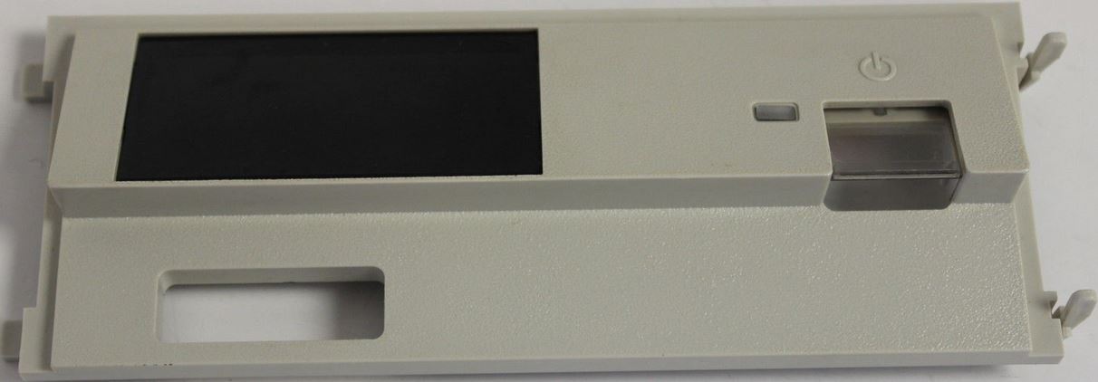
This is not the earliest, as it has the shutter over the Power Switch
Button. Note that the bezel hooks are on the LEFT and the bezel latches are on
the RIGHT. It has a Power Good LED and an Information Panel window.
Later 8595/9595 Op Panel Bezel, Rear

Note the small locating posts at the upper corners? Note the modular
assembly, with the white button frame being placed onto the bezel (grey). Peter
mentioned that the op panel PCB originally came off an older existing device.
Also note the LED window is covered with a darkly shaded piece of plastic. If
the plastic window got a little scuffed up, you can push the flexible sheet
out, and the tabs will pop out of the frame with no damage. To re-install the
window, put one tab in the slot, and bow the sheet a little until the tab
re-enters the opposite slot.
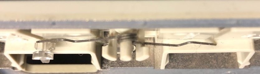
Op Panel Shutter Spring
The spring powering the shutter rests on a little hook molded into the
shutter. If the shutter haltingly raises, check to see that the end of the
spring is in the hook, not dragging between the front of the hook and the white
module. Note the white hook just above and right of the end of the spring. To
remove any spring tension from the shutter, place the end of the spring into
the hook.
Correct Spring Position (Lorenzo)
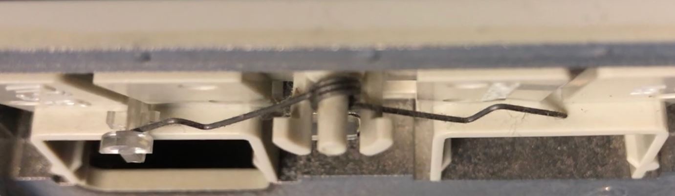
The photo above shows the shutter spring in the correct position.
Incorrect Spring Position (Lorenzo)
Note the shutter spring is in front of the little "wings" used to guide the
shutter up and down. The shutter spring rubs against the subframe, and the
shutter no longer moves smoothly. In addition, the shutter is pulled back into
the subframe causing resistance as well...
8595 / 9595 Op Panel PCB, Top (Jelte)
8595 / 9595 Op Panel PCB, Bottom (Jelte)
8595 Frame (Jelte)
See the rectangular holes on the left for the Op Panel Bezel hooks, while
there are similar "T" shaped holes to the right. Note there is only ONE set of
small holes for the Op Panel bezel at the top corners. Note the small hole for
the alignment pin in the upper left corner is horizontally elongated, while the
upper right pin hole next to the latch hole is round. This makes sense, as the
hooks on the left are inserted first, and the left pin makes an arc as it
enters the hole. The rightmost pin is near perpendicular as it enters the hole
near the latch.
9595 Single Serial Frame (Lorenzo)
Same as the -AKD, I would surmise the bezel mounting holes changed with the
9585 (K/N?) and 9595A (Dual Serial/Parallel) models.
Note that the hook /latch holes are slightly inward from center. Maybe
because it was better to not have the drive retainer hooks in-line with the
bezel fasteners? Dunno.
3511 Op Panel
3511 Op Panel Bezel, Front 64F0131
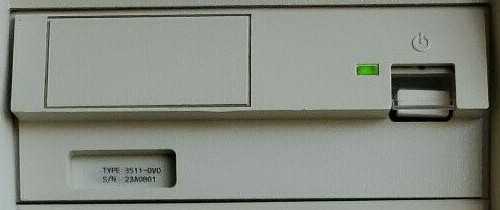
The 3511 uses a bezel derived from the "later" 8595 assembly - but with the
LED display window covered.
3511 Op Panel PCB, Top 64F0143 (Mad Max)
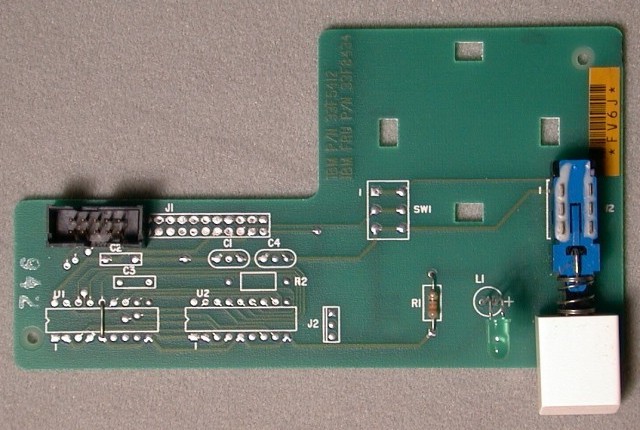
3511 Op Panel PCB, Bottom 64F0143 (Mad Max)
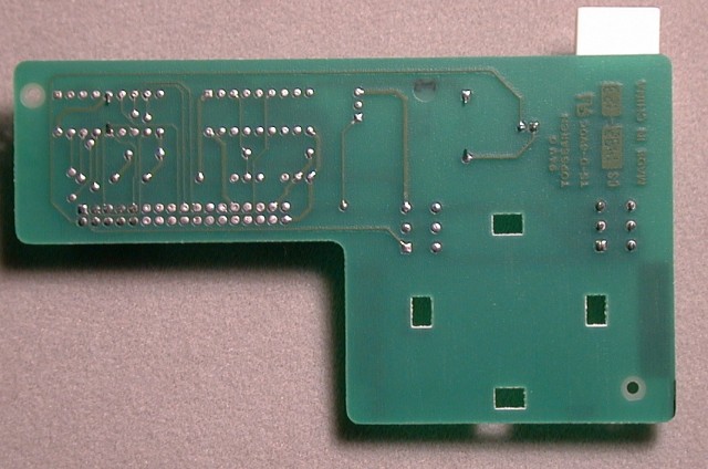
This is the same Op Panel PCB as in the original 8595. However, only the
power switch, Power Good LED & resistor, and a smaller (10-pin) header are
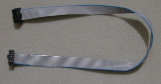
populated. There is a wire between pins 5 and 14 of the LED unit U1 -
redirecting the +5 V rail to pin 9 of the J1 header (normally +5 V is on pins
25, 27, and 31 - unpopulated here). The corresponding 10-wire cable can be seen
HERE.
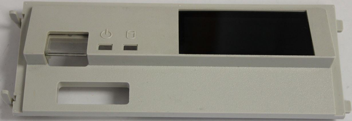
9585 Op Panel Bezel, Front 41G9550
9585 Op Panel
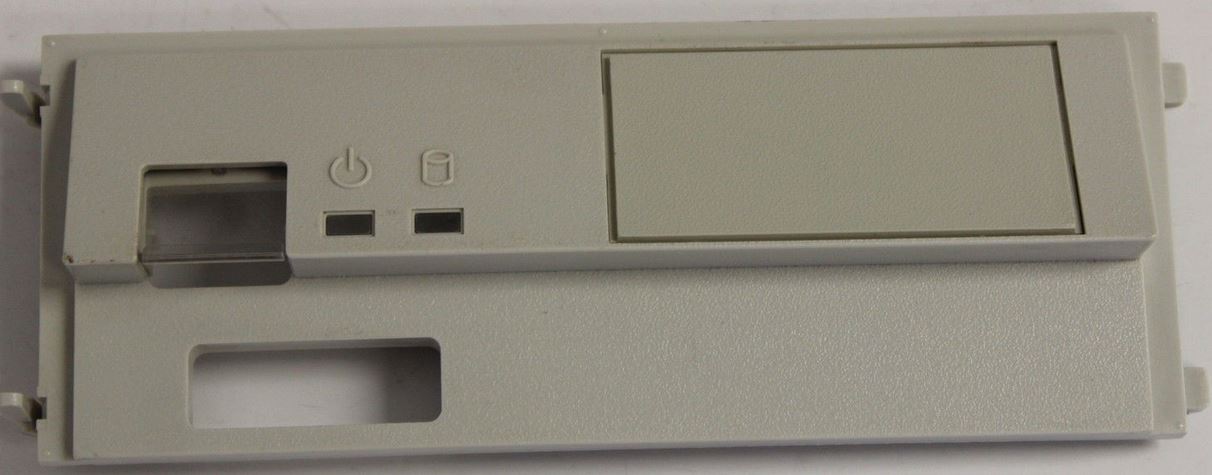
This bezel has a shuttered Power Switch Button, a Power Good LED, a HDD
Activity LED, but the Information Panel window has a opaque plastic insert. Note
the bezel latches are on the LEFT and the bezel hooks are on the RIGHT.
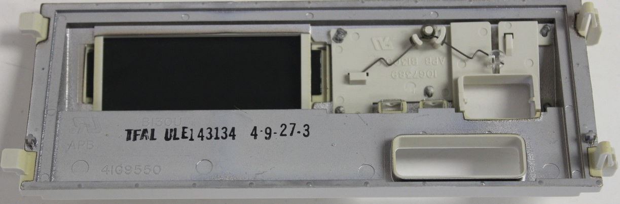
9585 Op Panel Bezel, Rear 41G9550
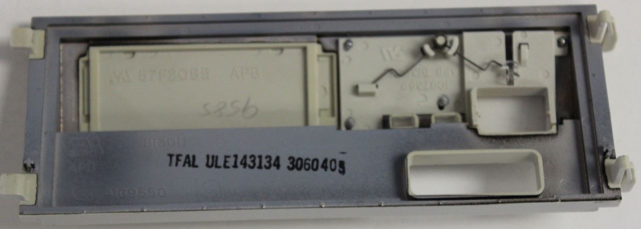
Note the small locating posts have been moved from the upper corners to just
above the lower hook / latch? Note that the Information Panel window insert
(57F2085) has the same tab arrangement as those for LED displays. The power
button frame has lost the well for a second push button, and a second LED light
pipe has been added.
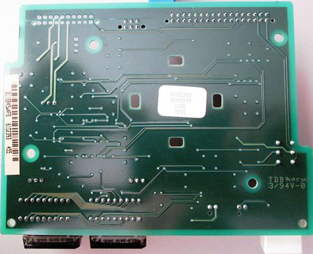
9585 Op Panel PCB, Top 61F3736 (David Beem)
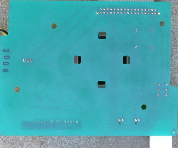
9585 Op Panel PCB, Bottom 61F3736 (David Beem)
9595A Op Panel Bezel, Front 41G9550
9595A Op Panel
This bezel has a shuttered Power Switch Button, a Power Good LED, a HDD
Activity LED, but the Information Panel window has a darkly shaded piece of
plastic. Note the bezel latches are on the LEFT and the bezel hooks are on the
RIGHT. The 9585 and 9595A use the same bezel.
9595A Op Panel Bezel, Rear 41G9550
Note that the Information Panel window insert has the same tab arrangement as
those for LED displays. The power button frame has lost the well for a second
push button, and a second LED light pipe has been added.
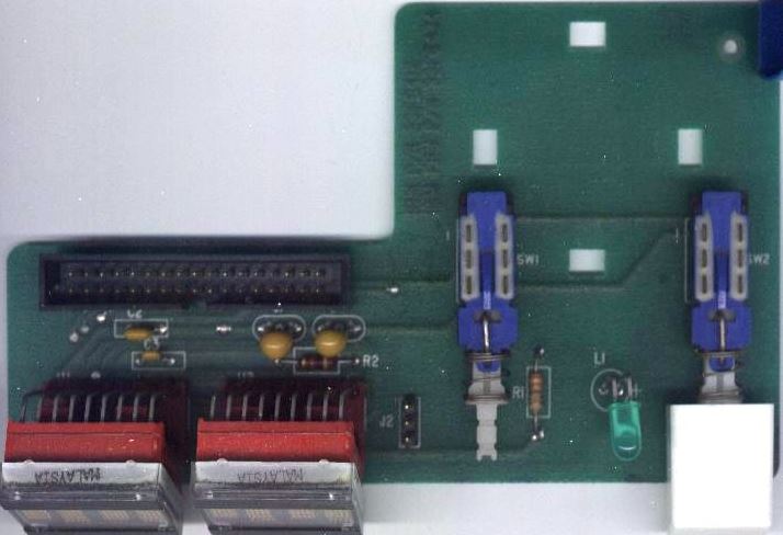
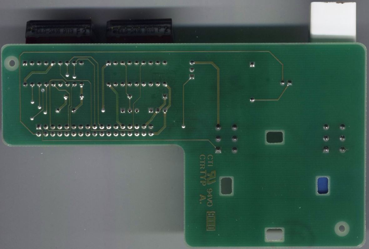
9595A Op Panel PCB, Top 92F0259 (Jelte)

9595A Op Panel PCB, Bottom 92F0259 (Jelte)
9585 and 9595A Frame (Jelte)
See that the hook -AND- latch >BOTH< use a "T" hole? Note there are
TWO sets of small holes for the Op Panel bezel pins, at the top corners -AND-
above the bottom hook / latch holes. I suppose you could use one LED bezels on
8595 >AND< 95A frames... Note the elongated hole for the top posts is on
the left, and the elongated hole for the bottom posts is on the right.
What is the second card guide doing there? See, the Op Panel board is in the
upper card guide, and the narrower bottom guides are empty. Note the notch in
the frame in the lower right (below right 4 character LED), and the
semi-circular relief in the plastic DASD Support Structure... Almost resembles
a relief for a thumb wheel... Multimedia Option?
Power Switch Test / Jump Start
Pull Op Panel out front of system. Leave PSU plugged in. Unplug the molex
connector(s) from the PSU if you don't want your hard drives to spin up/down
during the testing.
For the single LED (95 XP) Op panel: Short pin 1 (or 4) to pin 2 (or 5)
and the PSU should start.
For the dual LED (95A) Op panel: Short pin 1 to pin 2 and the PSU should
start.
Operator Panel Registers
See Hex 0108-010F for info about Op
Panel registers.
Panel Programs
PS2INF.ZIP Small program to access the LED Panel (DOS, OS/2 driver).
DLITEDOS DOS device driver for HD display on Model 95 LED Panel
PANEL OS/2 device driver for character display on Model 95 LED Panel
BASIC Way
From Peter (edited):
Use this little Basic program to write anything into the panel.
Substitute A$ with your text:
A$ = "133 MHz "
FOR q = 1 TO 8
OUT (&H107 + q), ASC(MID$(A$, (9 - q), 1))
NEXT q
You can as well use DEBUG's "OUT {portnumber} {value}" command to pipe into
the display. Write a text that includes 8 lines of out commands to the ports
108h - 10Fh with the hex character values for {value} and use
DEBUG<mytext.txt to bring it into the panel.
(30 is "0", 39 is "9", 41 = "A" 5A = "Z")
Linuxinfo
If you have a Model 95 (8595, 9595), you can get the source of linuxinfo,
that is linuxinfo.c. This
program shows you the current CPU-load, date, time and the kernel-version on
the 95s' LED display. The information is continuously scrolled from right to
left. This allows system-load-control, even if you are not logged-in and no
monitor is connected to the system (like in central computing rooms). As the
two very right LED letters are kept blank, it works great together with the IBM
SCSI subsystem driver with the command line-parameter ibmmcascsi=display.
LED Panel Odd Behavior
From Alfred Arnold:
Last week, I was able to get my hands on a 8595-AKF (Type 1
complex, 486DX33, no cache module :-( ). The price was on a per-kilogram basis,
so I was quite happy. However, when installing Linux and my own tool to display
some system statistics on the LED display, I noticed a strange behavior I
hadn't seen before on a 9595 with a P60 complex: Even under Linux, there seems
to be some type of 'demon' that regularly clears the right half of the display.
I also saw this under plain DOS, but I thought first this were a 'feature' of
the BIOS. However, since this also happens under Linux, either something on the
planar is slightly broken, or there are some implicit links between the LED
display and other parts of the planar's hardware I'm not aware of. I don't hope
it's the first case ;-)
From Peter:
> Even under Linux, there seems to be some type of 'demon' that
regularly clears the right half of the display.
On the -AKF this is surely a bug rather than a feature. The
LED-panel is directly controlled from the sysboard I/O ports and it looks like
a buggy display element (2 x 4 digits). Check if it is properly seated or has
bad solder spots. Also check if the panel cable is in good order and properly
seated.
Alfred Arnold retorts:
Hi Peter, took out my Tek yesterday evening and probed around a
little bit. It doesn't seem to be a problem in the display element itself,
since swapping them doesn't help...the interesting thing is that during POST,
the write signal for the bottom display half is overlayed with a 250 Hz signal,
which however has not full level. So either the driver chip on the planar has
gone bad or there is a short to another signal. Seems I have to disassemble the
whole beast :-/
And finally, the moment of discovery:
By the way, I was able to fix the display yesterday evening. There
was a bad contact in the display module's socket, but one that can make you
tear out your hair...there was no contact to the Vcc pin of the display, but it
still somehow worked because it supplied itself with power via the other signal
pins (probably via the usual CMOS protective diodes). You could put a scope on
the /CLR pin of the display module and see how the voltage started to ripple
when one digit was turned on. Turn on a second digit, and the voltage broke
down finally and the display resets...
8 "Lights" on Op Panel
I have been having some trouble with getting a Model 95 to see the optical
SCSI drive being added. I went in and unplugged the SCSI cable, and power cable
to reset everything and start over. Now I have 8 positions across the op panel
with a pattern of small dots (LEDs) and the machine goes no farther in the boot
process. What do the 8 position, all LEDs on suggest.
It suggests you pulled one end of the cable going to the LED display loose
at one end or the other or that you somehow damaged the cable to it. Check for
this small flat cable and make sure its OK.
Jack, I had high hopes that it would be that simple. I checked and
re-plugged both cables and did not change my symptom. Any other ideas. I have
an HMM dated Sept 1993. Where did you find the symptom info.? Did you get it
from the HM manual?
From Jack Gulley:
The HMM will not give you details on what's wrong. The symptoms
indicate one of the lines to the operator panel has a hot or shorted bit. If it
is the same bit in each of the 8 display position, it indicates a common line
or driver problem. If the bit come on as soon a power comes on and nothing else
ever displays, then it very likely the operator panel is blown. Problem
isolation is simple - replace the cable, then the electronics at each end of
the cable, after first making sure everything was plugged in and the cable not
damaged.
| 

