|
Processor Complex Index
PS/55 Model 5560 Model 90 redesigned by IBM Japan
DBA-ESDI Hard Drive Interface
8590 / 9590 Planar
Early 8590 Planar
System Firmware
Planar Ports
Mouse and Keyboard Ports
Serial Ports
Parallel Port
Front Panel Connector Pinout
DBA Connectors on 8590 (J16 and J23)
8590 and 9590 Planar Differences
KB / Mouse Port Filter
64K Colors Supported under W98SE
Video RAM
Video RAM Installation
9590 Floppy Controller
Memory Riser
Orienting SIMMs on Riser
Loading SIMMs
8590 Memory Parity Errors / Configuration H095511
ECA084 Model 90 Memory Riser Card
Error 201
Plastic SIMM Holders
Memory Expansion Boards
Planar ADF Sections (PFF6F.ADF)
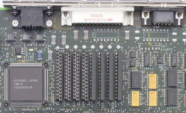
8590 / 9590 Planar FRU P/N 64F3287, P/N 91F7458
![[P]](/other/img/photo.gif "Front")
BT1 Battery (CR2032)
F1 Keyboard Fuse
J1,3,6 32-bit MCA slot
J2 Front Panel connector
J4 32-bit MCA slot w/ AVE
J5 Fan connector (-12 V, GND)
J7/8 Processor Complex slot
J9 HDD15 video connector
J10 Power-on password
J11,14 Memory riser slot
J12 DB25 Serial port
J15 40-pin Floppy Connector (1 key)
J16,23 DBA-ESDI connector or pads (info)
J17 DE9 Serial port
J18 Parallel port
J19 Mouse port
J24 Keyboard port
J25,26 Power Supply connector
Y1 32.768 KHz xtal (RTC)
TP1 Power Good test point
U1 LM386 Audio op-amp (PC Speaker)
U7 Dallas DS1210 NVRAM controller
U9 41.5390 MHz osc (XGA)
|
U13 14.3181 MHz osc (adapters, 85F0464?)
U14 37F0842 (XGA)
U16,19,20 TDK ZJY-2P (XGA)
U18 25.175 MHz osc (XGA)
U21 44.9000 MHz osc (XGA)
U22 28.3220 MHz osc (XGA)
U23 Dallas DS1285 RTC/CMOS
U24 8Kx8 SRAM (NVRAM)
U25-29 Video Memory
U36,38,40 Video Memory
U64 74F5160, Toshiba TC110GC9AF XGA
U65 40.0000 MHz osc (planar I/O bus?)
U67 85F0464 ASIC (int/KB/mouse)
U70,71 Pads for 2x 74ALS244
U72 64F3110, TI CF61533FN
U77 22.1184 MHz osc (UART)
U84 82077AA Floppy controller
U85 Pads for IC (?)
U87,88 64F0942 or 33F5469 ASIC (UART/parallel)
U89 1x9 solder pads (?)
U92 24.0000 MHz (FDC)
ZM1-4 Spare position
|
U24 8Kx8 SRAM (NVRAM)
SRM2264LC-12
(alt) or
Sony CXK5864BP-12L
U77 22.1184 MHz Clock for "Type 3 High-Speed UART". Divided by 2.
U64 XGA Controller:
Early TC110GC9AG / 1888676, Late TC110GC9AF / 74F5160
VRAM Toshiba
TC524256BZ-10 / NEC D42274V-10 / OKI MSM514262
TDK ZJY-2P 2 Line
Common Mode Choke (datasheet)
U14 37F0842 equivalent to
INMOS G190 Serializer Palette DAC
U64 TC110GC9AF equivalent
to INMOS G200 XGA Display Controller
U31 32K sprite memory,
between U64 and J14. SRM20256LM12 or CXK58257AM-12L
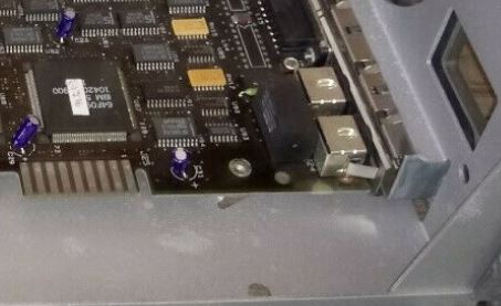
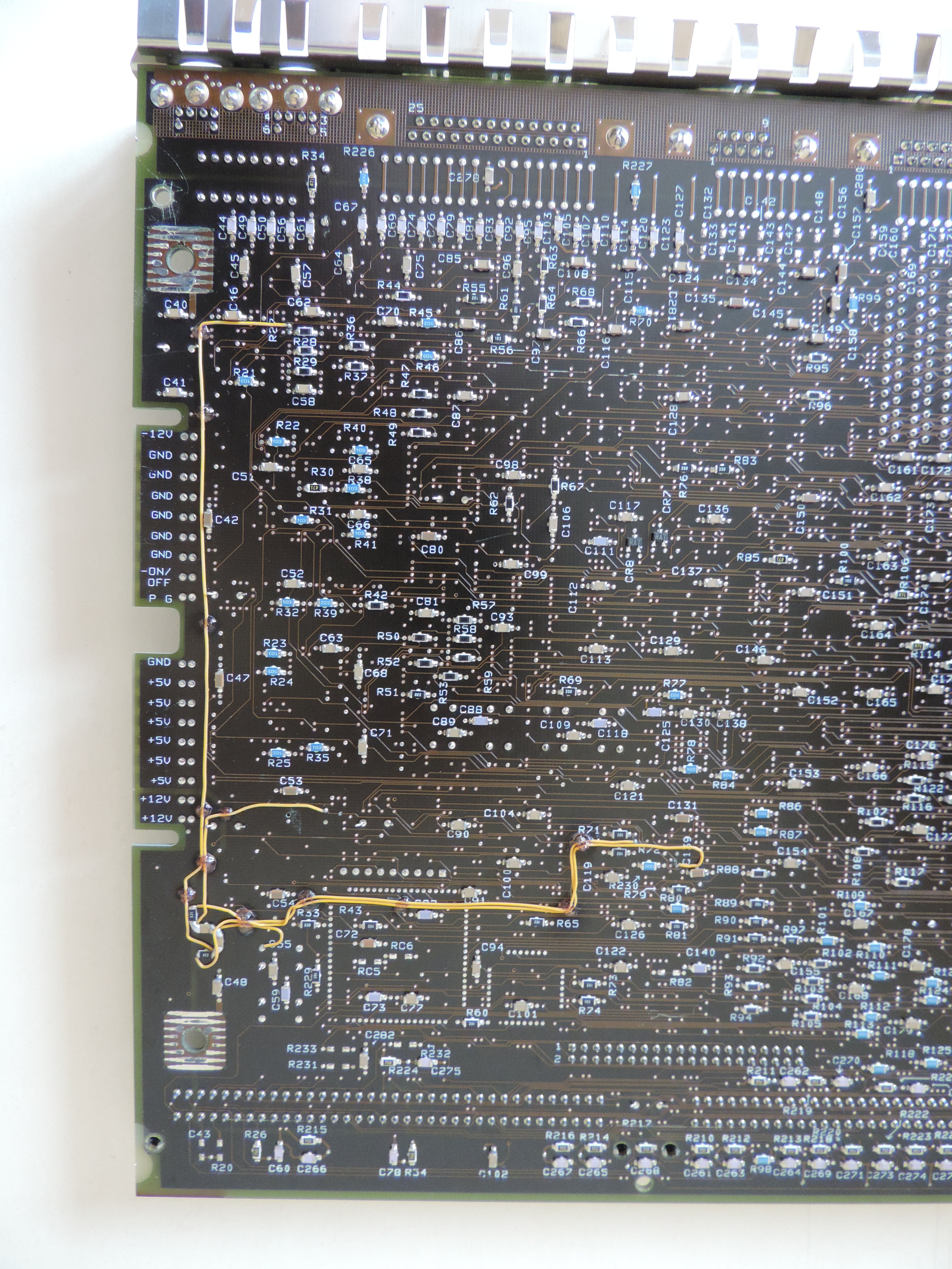
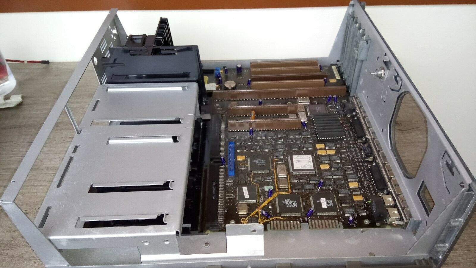
Early 8590 Planar (FRU 64F3288, sticker 91F7467)
This version of the planar can be found in some early 8590s, and is largely
identical to the later and more common revision. The most notable difference is
the strangely positioned fan connector (J5) and presence of the
keyboard and mouse filter (LN5).
There are some other minor differences in the speaker amp area, and some
of the resistor networks that are populated on the later version are missing
here. These early boards also tend to come with quite a few bodge wires and
other fixes (see HERE or
HERE).
Some of these early boards are cut differently in the area where the front
panel and fan connectors are located (see the dashed outline). An example of
such a board can be seen in this
video (16:15).
U70 and U71 are populated with 2x 74ALS244 on these early boards. Some
samples have a PLA at position ZM4 with a bunch of bodge wires going to various
places of the planar (see the video linked above).
The two DBA-ESDI connectors (J16,23)
are usually populated on these older boards.
System Firmware (POST & BIOS)
Firmware stored on the Processor Complex.
Planar Ports

Mouse and Keyboard Ports
The new keyboard/mouse controller used on Model 90 and Model 95 XP 486
systems provide additional functions for mouse support. These include the
ability to separately receive and send data to the keyboard and mouse ports
simultaneously. This is not possible on previous PS/2 systems as only one I/O
port is used for both keyboard and mouse data.
Source HERE (physical page 37).
Serial Ports (In Accordance With EIA-232-D)
Two serial ports:
- Port #1 - DB25, Built-in planar feature
- Port #2 - DE9, Planar device #6
Pinouts HERE.
Note: Current Loop interface is not supported on
either serial port.
Dual DMA serial ports (Type 3 Serial Controller), one DB25 and one DE9. The
DE9 port requires feature number 0217 or 0242 for attaching devices with 25-pin
D shell connectors.
The DMA serial port supports 300 bps to 345.6K bps. DMA reduces CPU loading
and overhead at higher speeds. Speeds up to 345.6K bps are supported using IBM
Enhanced EIA-232-D which requires a special shielded cable up to 20 feet
long.
Ether serial port can be set to Serial 1-8, with different arbitration
levels for Transmit or Receive. Both ports are limited to Int 3 (Serial
Controller chapter of HITR says Type
3 Serial Controllers can use Int3 or Int4. YMMV).
Parallel Port
DMA Parallel Port
With most Microsoft products, enabling "Arbitration Level" results in problems,
since IBM developed the DMA parallel port prior to the ECP/EPP industry
standards being developed. You may have to disable Arbitration Level if your
parallel port device fails to work.
Parallel Port Resources
PARALLEL 1 (03BC-03BF 1278-127F int 7)
Note: Parallel Port Arbitration Level "Disabled" sets
Parallel 1 to Bi Directional mode
PARALLEL 2 (0378-037F int 7) Bi Directional
PARALLEL 3 (0278-027F int 7) Bi Directional
PARALLEL 4 (1378-137F int 7) Bi Directional (or so the Model 90 TR says)
Disabled (no parallel port at all)
Note: The Parallel_1 dual I/O address range of
(03BC-03BF 1278-127F int 7) has the Bi-Di compatible port at 03BC-03BF, while
enabling dedicated or shared DMA operations enables DMA operations at 1278-127F
(Model 90 TR says 1278-127D... YMMV). The split was due to the old [and
obsolete] MDA and Printer adapter I/O range.
Note: IBM defines Parallel_2 as 0378-037F int 7,
while everybody else calls it LPT1... So if you use a MS product, and your
printer won't print, check to see if both refer to the same I/O range. IBM only
supported Int 7 on any PS/2 planar parallel port.
Front Panel Connector Pinout
Looking at the planar (male) connector from the front (where the plug would go):
|

|
| Pin |
Function |
Pin |
Function |
| 1 |
PWR LED (-) |
8 |
PWR LED (+) |
| 2 |
HD LED (+) |
7 |
PWR Switch (+) |
| 3 |
HD LED (-) |
6 |
Speaker (-) |
| 4 |
PWR Switch (-) |
5 |
Speaker (+) |
|
Note: The pins are marked differently at the
bottom of the PCB (see the photos above).
DBA Connectors on 8590 (J16 and J23)
IBM brought out a "low-end" Model 90 with
DBA-ESDI and a
386DX-20 processor board.
A big insurance company (Aetna?) had 386DX-20 complexes made for it - the
"Type 0". Apparently, so did Royal Bank.
DBA-ESDI Boot Support with the Type 0
Daniel Hamilton dug down into the Type 0 abyss and found out while yes you
can boot from the DBA-ESDI drive, you must still have a SCSI drive on a Spock
to provide IML. Read his further bone-chilling adventures in the DBA-ESDI
Temple of Doom HERE
Being able to boot from a DBA-ESDI drive as C: offers a simple upgrade path for
the Model 70 to Model 90, just by swapping the drive out.
Martin Adams:
One advantage the model 90 has over the 77 is the 8 SIMM slots.
Eight 8MB SIMMs are allot cheaper than four 16MB sticks right now. We also have
the caching SCSI that could have its cache upgraded. You don't have to pull
adapter cards to reconfigure RAM. I prefer the planar mounted bus connectors
too.
Differences between 8590 and 9590 Planars
9590s lack DBA-ESDI artifacts, have 512K VRAM soldered on planar, and is a
pretty green. The 9590 planar shows up as an XP 90 system board under setup.
The parallel port has DMA support, but no Expressprint and no Wake on Ring.
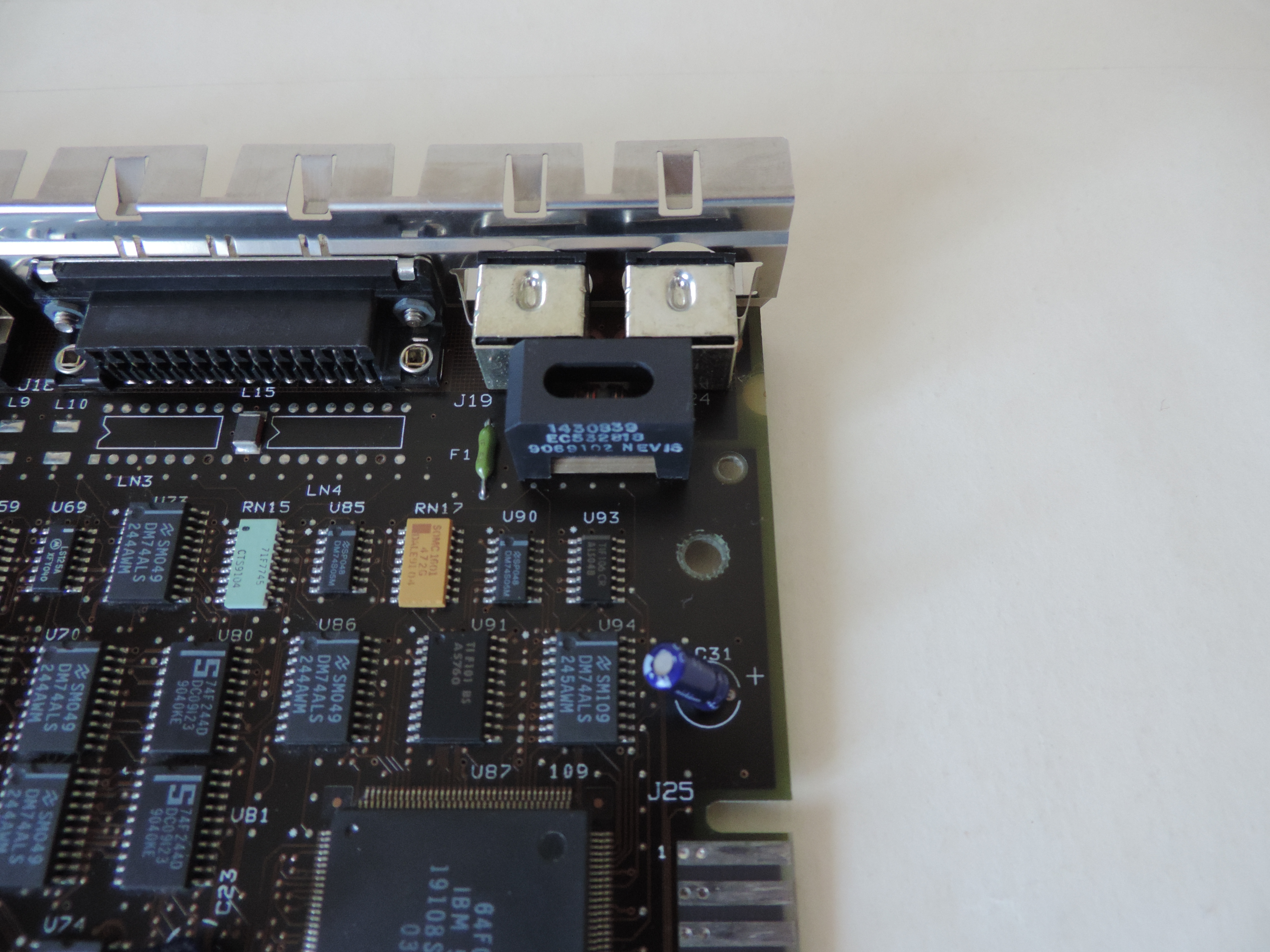
KB / Mouse Port Filter (LN5)
While consoling Tomáš Slavotínek over his lack of a Model 90, he sent me
a picture of a sweet early production Model 90 from an auction. Not even dust
inside...
And what do I see but an EMI filter next to the KB / Mouse port. Why is it
present on the early boards but not on the later ones? We will most likely
never know, the engineering notes were hidden (oh, the humanity!).
A better picture of the filter HERE
(different sample).
64k Colors under W98SE
W98SE has 640x480x64k at 60Hz support. This requires 8 Video ZIPPs to be
installed.
Video RAM
VRAM chips are Toshiba TC524256BZ-10 or NEC D42274V-10. Model 90 systems
have 8 sockets or 4 sockets / 4 soldered VRAM.
Note: Any reference that says the 9590 has XGA-2
on the planar IS WRONG!!! It has 512K soldered on the planar, plus 4 sockets
for the 512K video memory upgrade. To make the 9590 ISO compliant they had to
install XGA-2 cards in them.
Ed. It is possible (Loch Ness Monster or Big
Foot likely...) that IBM did do a few XGA-2 Model 90 planars. Never seen or
heard of one. BUT... I have seen a picture of a P75 with an active matrix LCD
screen instead of a plasma display. So _MAYBE_ the IBM Canada site referred to
a short lived variant...
Video RAM Installation
Note the white dots towards the rear of the planar.
Insert VRAM Into Sockets
|
Place insertion tool (1) over empty VRAM socket (If you have one!)
Align beveled corner (2) of VRAM chip towards the dot on the planar.
Carefully align the pins with the socket (3) and firmly press the
module straight down into place.
Do not start one end before the other. You can slightly rock the chip side
to side to install into a stiff socket, but be careful!
|
Pay attention to the pins of the VRAM ZIP when you install it. I installed
the VRAM ZIPs into my 90 and was more than a little surprised when the video
displayed as complete garbage. Turns out I had a chip off by one column of pins
and I never saw it until I looked with a lamp.
Which Slot for the XGA-2?
For complexes with search IML BIOS (T1 / T2 with upgrade BIOS, all T3 / T4),
the XGA-2 may be installed in Slots 1, 2, and 4. For T1 or T2 with non-IML
search BIOS, Slot 1 must be filled with an IBM SCSI adapter, and only Slots 2
and 4 may be used for the XGA-2. Slot 3 is an AVE slot and is physically
incompatible. For a full discussion, go
HERE.
Note: The AVE at the rear of Slot 3 is disabled
when XGA is in extended graphics mode.
9590 Floppy Controller
Intel 82077AA. Go HERE for more
info. The Model 90 uses the
40-pin floppy header
on the planar. The Model 90 Type 2 diskette controller is compatible with the
Type 1 controller used on previous PS/2 systems. It supports:
- 1.44 MB 3.5" diskette drives
- 2.88 MB 3.5" diskette drives
- Internal tape backup unit
- 1.2 MB 5.25" 1 inch high diskette drive. (supported only by the Type 2 controller)
Memory Riser
Orienting SIMMs
When inserting SIMMs onto the riser, orient the notch on the SIMM with the
notch on the riser. Always wondered why the riser had that seemingly useless
extension to the right. Think of the riser as a big SIMM with it's notch. Like
to like...
Plastic SIMM Holder Clips
There also was a problem with local power drops on the early Model 90 memory
riser cards (the ones with all-plastic SIMM sockets). Improved versions had
metal holder clips. And - logically - you should not mix the two versions.
Loading SIMMs Onto Memory Risers
Memory must be loaded in matched pairs (size and speed) into sockets J1+J3
and J2+J4 for interleaved configurations (Type 1, 3, and 4 complexes). Type 2
complexes allow you to stuff SIMMs in the sockets in any order or combination,
but if not in matched pairs (J1+J3, J2+J4) there will be a performance hit.
Note: SIMM pairs do NOT cross risers!
Don't stuff one riser with modules (especially double-sided) and leave the
other blank. It *hates* imbalance on the memory drivers. Try to organize them
the way to achieve a balanced load on *both* memory risers by having equal
number of chips per pair, then on both risers. Certain releases of the Model 90
had problems with the double-sided SIMMs - especially with the 8MB...
Ed. Please genuflect while absorbing the
riser/slot illustration. Remember, for interleaved configuration, you place
matched speed/size SIMMs in A1-B1, A2-B2, and so on. Please note that the SIMM
pairs do NOT cross between memory risers. The Model 95 uses separate A and B
banks (A1, A2, A3, A4 then B1, B2, B3, B4) while the Model 90 uses both banks
on both cards, A1, A2, B1, B2 then A3, A4, B3, B4).
8590 Memory Parity Errors / Configuration H095511
Unbalanced loading of SIMMs may cause parity errors when using four or more SIMMs.
Classify each SIMM as HIGH or LOW LOAD based on the following:
- Count total modules (chips) on both sides of SIMM.
- If 12 or less, the SIMM is LOW LOAD.
- If greater than 12, the SIMM is HIGH LOAD.
This chart shows number of modules (chips) on each type of SIMM and its LOAD:
| Size |
Modules |
LOAD |
| 2MB |
10 |
LOW |
| 4MB |
9-12 |
LOW |
| 2MB |
18-24 |
HIGH |
| 8MB |
18-24 |
HIGH |
If the SIMMs are either all HIGH LOAD, or all LOW LOAD, then install in both
memory riser cards and exit this procedure.
Memory SIMM Configuration Procedure
Note: For this procedure, memory will always be
installed in matched pairs starting with J1&J3 then J2&J4 on memory
riser cards. Riser card in J11 will always be fully populated first.
- Install low load matched pair in J2&J4 of memory riser in J11.
- If only 4 SIMMs will be installed, go to step 3, if not, proceed with step 4.
- Install two remaining matched SIMMs in J1&J3 of memory riser in J11 and exit.
- For 6 SIMMs go to step 5 (EXAMPLE 1) for 8 SIMMs go to step 7 (EXAMPLE 2)
- For a LOW LOAD matched pair, install in J1&J3 of riser J11 and go to
step 6. If remaining memory is HIGH LOAD then install a matched pair in J1&J3 of riser in J11.
- Install remaining HIGH LOAD matched pair in J1&J3 of memory riser in J14 and exit.
- Install a HIGH LOAD matched pair in J1&J3 of memory riser in J11.
- If remaining memory is all HIGH or all LOW, install on memory riser in J14 and exit.
- Install remaining LOW LOAD matched memory in J2&J4 and HIGH LOAD
matched memory in J1&J3 of the memory riser in J14 and exit.
The following are examples of how to implement this procedure:
Example 1:
| Riser J11 |
Riser J14 |
| J4 |
2MB LOW |
J4 |
|
| J3 |
2MB LOW |
J3 |
8MB HIGH |
| J2 |
2MB LOW |
J2 |
|
| J1 |
2MB LOW |
J1 |
8MB HIGH |
| Connector |
|
Connector |
|
This system has six SIMMs and it has been determined that the four 2MB SIMMs
are LOW LOAD and the two 8MB SIMMs are HIGH LOAD. According to this procedure,
no change is required.
Example 2:
| Riser J11 |
Riser J14 |
| J4 |
2MB LOW |
J4 |
8MB HIGH |
| J3 |
2MB LOW |
J3 |
8MB HIGH |
| J2 |
2MB LOW |
J2 |
8MB HIGH |
| J1 |
2MB LOW |
J1 |
8MB HIGH |
| Connector |
|
Connector |
|
The system above has eight SIMMs, four HIGH LOAD and four LOW LOAD. The
system should be reconfigured as shown below in example 3:
Example 3:
| Riser J11 |
Riser J14 |
| J4 |
2MB LOW |
J4 |
2MB LOW |
| J3 |
8MB HIGH |
J3 |
8MB HIGH |
| J2 |
2MB LOW |
J2 |
2MB LOW |
| J1 |
8MB HIGH |
J1 |
8MB HIGH |
| Connector |
|
Connector |
|
ECA084 - Model 90 Memory Riser Card
If memory riser card FRU P/N 33F4905 is populated with "MIXED SIMMs" and is
experiencing any of the following errors: DOS NMI, OS/2 TRAP 0002, POST, or
diagnostic memory errors, replace both memory riser cards with new FRU P/N
81F8823 (two required).
Note: "MIXED SIMMs" is defined as SIMMs with 12
modules or more per SIMM, mixed with SIMMs having less than 12 modules per SIMM
mounted on the same riser card. If FRU P/N 81F8823 is already installed, this
ECA is not applicable.
Original scan from Al Savage out on the left coast.
The "bad" riser (33F4905) has six electrolytic capacitors on the front. The
"good" riser (81F8823 or 81F8827) has only the silk screen outlines for the
caps (also a lot more SMD resistors and caps on the back). Both risers have
metal clips and white SIMM sockets.
Error 201
Error code 201 says "Reseat system board memory" and can afflict the planar
as well as the memory only. I would suggest to remove the memory risers, reseat
all modules, plug them back and see if they are seated properly.
I would also suggest that you start with one single pair of matching memory
modules in the connectors J1 + J3 on riser J11 - the one closer
to the processor board. This is just to test out if your problem is memory- or
planar related.
If the machine comes up fine (counts memory) - install the next pair in
sockets J1 + J3 in Riser J14 - the on closer to the power supply to keep
balanced load of the memory decoder lines. As I wrote: the Model 90 has a
sensible feeling for imbalanced memory modules and may "spin out" with somewhat
strange and unexplainable errors by no obvious reason. There once was a
recommendation from IBM on that topic and they explicitly mentioned it for the
Model 90 - particularly for those cases where double-sided memory modules are
used (which put a higher load on the decoder lines).
Still Getting Memory Errors? (from William)
Thoroughly clean the system unit. Remove all cards, complex, and both memory
risers. Blow them out thoroughly. You may have a bit of dust or other crud
that's fallen into a socket and is causing problems. My Model 90 did this with
a dust bunny in the complex socket that was causing continuous memory errors in
the same memory socket even after riser and SIMM swaps.
Memory Expansion Boards
You can't. Sort of. The 90 (and 95) does not cache expansion board memory.
So in addition to the overhead in negotiating for control of the Micro Channel
bus, you have to give up the advantage of the 486 cache...
Warning! Memory adapters on the Micro Channel are
NOT supported, although they may work. However, it is strongly recommended not
to use them as they will significantly degrade the overall performance of the
system, as memory on the Micro Channel is not cached.
Note: Memory expansion adapters are only supported on
8590 special bid systems with 386 complexes (FRU P/N 33F8454) Known -402 are
from WorldCom, Aetna, Royal Bank.
Ed. With the advent of eight SIMM sockets and
higher density SIMMs, the need for memory cards fell off dramatically...
AdapterId FF6F Built In Features
Total System Memory
   Installed Memory. . . . . . . . . . . . : nnnnKB (nn.nMB)
   Useable Memory  . . . . . . . . . . . . : nnnnKB (nn.nMB)

Built In Features
   Installed Memory. . . . . . . . . . . . : nnnnKB (nn.nMB)
   Diskette Drive 0 Type . . . . . . . . . : 1.44MB 3.5"
   Diskette Drive 1 Type . . . . . . . . . : Not Installed
   Diskette Drive 2 Type . . . . . . . . . : Not Installed
   Math Coprocessor. . . . . . . . . . . . : Installed
   Display F1 prompt to access System Pro. : Yes [T4 only?]
   Serial Port   . . . . . . . . . . . . . : SERIAL_1 (DB25 port)
   Serial Transmit Arbitration Level . . . : Shared 4
   Serial Receive Arbitration Level. . . . : Shared 3
   Parallel Port . . . . . . . . . . . . . : PARALLEL_1
   Parallel Port Arbitration Level . . . . : Shared 7
   Preempt Enable/Disable  . . . . . . . . : Enable
   Video I/O Address . . . . . . . . . . . : Instance x: nnnnh - nnnnh
   Video ROM Address Space . . . . . . . . : Annnn - Annnn
   Video Arbitration Level . . . . . . . . : Arbitration Level x
   Video Fairness. . . . . . . . . . . . . : Fairness xx
   Useable System Board Memory . . . . . . : Parity [T3, T4 only]
   Bypass System Programs on Error . . . . : Disabled [T4 only]
   Processor . . . . . . . . . . . . . . . : Pentium 60 [T4 only?]

Slot 1 - (Card Name)

Slot 2 - (Card Name)

Slot 3 - (Card Name) [This is an AVE slot, XGA and XGA2 will not fit...]

Slot 4 - (Card Name)

Planar Device 5 - Integrated Fixed Disk and Controller [T0 only]
   DMA Arbitration Level . . . . . . . . . : Level x
   DMA Burst Pacing Interval . . . . . . . : xx Microseconds
   DMA Pacing Control  . . . . . . . . . . : Disabled
   Time To Release . . . . . . . . . . . . : x Microseconds
   Fairness On/Off . . . . . . . . . . . . : On
   Primary/Alternate Port
Addresses  . . . : Primary

Planar Device 6 - Serial Port No. 2 (DE9 port)
   Serial Port . . . . . . . . . . . . . . : SERIAL_2
   Serial Transmit Arbitration Level . . . : Shared x
   Serial Receive Arbitration Level. . . . : Shared x

Planar Device 7 - Integrated Fixed Disk and Controller [T0 only]
   DMA Arbitration Level . . . . . . . . . : Level x
   DMA Burst Pacing Interval . . . . . . . : xx Microseconds
   DMA Pacing Control  . . . . . . . . . . : Disabled
   Time To Release . . . . . . . . . . . . : x Microseconds
   Fairness On/Off . . . . . . . . . . . . : On
   Primary/Alternate Port
Addresses  . . . : Alternate

Planar Device 8 - Empty
System Memory Explained
Total System > Installed Memory = Planar plus memory expansion adapter
[minus defective or misconfigured memory]
Total System > Useable Memory = Installed minus any ROM shadowing
[minus defective or misconfigured memory]
Built In Features> Installed Memory = Planar memory only
[minus defective or misconfigured memory]
Diskette Drive x Type
1.44MB, 2.88MB
Serial Port [DB25 or DE9 Port]
Serial 1 - 8 or disabled. Must be
enabled if using an ASCII terminal as a system console.
<"SERIAL
1 (03f8h-03ffh 083f8h-083ffh, int 4)>, 2
(2f8-2ff 82f8-82ff, 3), 3 (3220-3227 b220-b227, 3), 4
(3228-322f b228-b22f, 3), 5 (4220-4227 c220-c227 3), 6
(4228-422f c228-c22f 3), 7 (5220-5227 d220-d227
3), 8 (5228-522f d228-d22f 3), Disabled
Serial Transmit Arbitration
Level
Use any level. Shared with other devices.
Dedicated, only this device can use that level.
<"Shared
4" >, 3, 1, 0, 7, 6, 5, Dedicated 7, 6, 5, 4, 3, 1, 0,
Disabled
Serial Receive Arbitration
Level
Use any level. Shared with other devices. Dedicated, only this
device can use that level.
<"Shared
3>, 1, 0, 7, 6, 5, 4, Dedicated
7, 6, 5, 4, 3, 1, 0, Disabled
Parallel Port
Parallel 1 through 3 or disabled.
<"PARALLEL 1" (03bc-03bf
1278-127f int 7)>, 2 (0378-037f int
7), 3 (0278-027f int 7), Disabled
Note: PARALLEL_2 is the
one Windows calls LPT1!
Note: PARALLEL_1
includes the I/O range 1278-127D to support DMA
operations. DMA can be turned off via Arbitration Level
if it is incompatible.
Parallel Port Arbitration
Level
Use any level. Shared, other devices
can use same level. Dedicated, only this device
can use that level. <Disabled> sets port in
compatibility mode [known as bidirectional].
<"Shared
7">, 6, 5, 4, 3, 1, 0, Dedicated 7, 6, 5, 4, 3, 1, 0,
Disabled
Note: IBM
developed the DMA parallel port prior to the ECP/EPP industry
standards being developed. If you are using a parallel
port connected device and it is misbehaving, Disable the
Arbitration Level. Sad but true....
Preempt Enable/Disable
Complex CPU can preempt continuous data
transfers by other devices for its use of MC.
<"Enable">,
Disable
Video I/O Address
Address range for display controller registers,
and location of video coprocessor registers.
<"Instance 6: 2160h - 216Fh">,
1 (2110-211F), 2 (2120-212F), 3 (2130-213F), 4
(2140-214F), 5 (2150-215F)
Video ROM Address Space [Slot
0 in "Memory Map"]
Memory address range used for system video
ROM.
<"C0000-C1FFF" >,
C2000-C3FFF, C4000-C5FFF, C6000-C7FFF, C8000-C9FFF,
CA000-CBFFF, CC000-CDFFF, CE000-CFFFF, D0000- D1FFF,
D2000-D3FFF, D4000-D5FFF, D6000-D7FFF, D8000-D9FFF,
DA000-DBFFF, DC000-DDFFF, DE000-DFFFF
Video Arbitration Level
Video sub-system arbitration levels.
<"Arbitration level 13">,
12, 11, 10, 9, 8, 14
Video Fairness
Whether video sub-system coprocessor
follows fairness algorithm for bus usage.
<"Fairness On">, Off
ADPItem 1 Usable System-Board
Memory (Exec)
Type of Usable Memory on planar.
Either parity or error-correcting-code (ECC)
Bypass System Programs on
Error [T4 only]
Enabled Disabled
Processor (Exec)
Pentium 60 [T4 only?]
| 