|
@0708.ADF BusLogic BT-646 S/D SDC3211F FAST SCSI
@0709.ADF Storage Dimensions SDC3211F FAST SCSI (Same board, different ADF!)
BT-646 ADF File (same as the first file above + readme)
MultiMaster Device Drivers
BT-646A Files (archived, broken links)
BT-646 User's Guide
BT-646 Fast Micro Channel Host Adapter Technical Reference P/N 3002113
Buslogic BT64x - General Information
OS/2 Switches
BT-646 / SDC3211F
ROM Images
Access BusLogic Firmware Menus
BIOS Revisions
ADF Sections
BusTek/BusLogic was bought by Myles, which was then bought by LSI.
BT-646S/D SCSI Adapter for Micro Channel Systems
32-bit bus master DMA transfers of up to 40MB/second across the MC bus, up
to 10 MB/sec synchronous and up to 7 MB/set asynchronous SCSI data transfers.
Support for up to seven SCSI devices, hard drives with up to 8GB capacity each.
Enhanced SCSI-2 features: scatter-gather, disconnect-reconnect, and command-tag
queuing.
BT-646 S/D and SDC3211F 32-Bit Fast SCSI-2
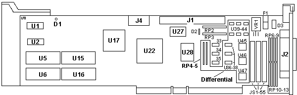
D1 LED
D2 1N5820
D3 1N5817
F1 Littelfuse MSF 125 V / 1.6 A
J1 50 pin header
J2 HPDB50 port
J4 Power
JS1-55 0 Ohm shunts (-S only)
RP2,3 CTS 4610X-1-101 (-S only)
RP4,5 10X-1-221 (-D only)
RP6-13 4610X-2-151 or -331 (-D only)
U1,2 KM6865BJ-20
U5 Firmware high byte
U6 Firmware low byte
|
U15 BIOS high byte
U16 BIOS low byte
U17 AMD N80C186-20 (MPU)
U22 BusLogic 80C20 (DMA Busmaster)
U27 40.0000 MHz osc
U28 SCSI IF Ctrlr
U33 DM7407M
U34 74F04
U35 7408D (-D) F08 XAC250 (-S)
U36-38 DM74LS08M (-D only)
U39-44 TI 751768 (-D only)
U45-47 DS36954AV (-D only)
VR1 LT1086CT 2.85 (-S only)
|
U28 may be an Emulex 2400150 or a
QLogic FAS236FAS236 datasheet
BT-646S single-ended termination - has
RP2 and RP3 only.
RP2, R3 - 10-pin 100 ohm SIPs containing 9 bused 100 ohm
resistors (CTS 4610X-1-101)
BT-646D differential termination - has
RP6-RP13
RP6,8,10,12 are 10-pin SIPs with 5 isolated 150 ohm resistors (Bourns
4610X-2-151)
RP7,9,11,13 are 10-pin SIPs with 9 bused 330 ohm resistors. (Bourns
4610X-1-331)
DS36954AV The DS36954 is a low power,
quad EIA-485 differential bus transceiver especially suited for high speed,
parallel, multipoint, I/O bus applications. Five devices can implement a
complete SCSI initiator or target interface. Three transceivers in a package
are pinned out for data bus connections. The fourth transceiver, with the
flexibility provided by its individual enables, can serve as a control bus
transceiver. Datasheet
ROM Images
"27128" silk screened inside socket, but it used 27C256-12 (DIP-28)
646s-336.zip Firmware 3.36 and SCSI BIOS 4.70
646_336f.zip Firmware 3.36 only (image repeated twice, unlike above)
BT646_uCode_00-338 SDC3211F Firmware BIN file, 3.38 Even (U6)
BT646_uCode_01-338 SDC3211F Firmware BIN file, 3.38 Odd (U5)
Looks like they diddled with it, 0000-03FF is all 0s, 0400-07FF are data.
BT-646x Host Interface Microprocessor
A 20 MHz Intel 80186 16-bit MPU is used to supply the speed for low command
overhead. This MPU coordinates all activity on the BT-646S/D under the
direction of the board’s firmware, including initialization, command
decoding, interrupt generation, and control of the data flow among the
board’s components.
Buslogic Tips
- Ensure that all Buslogic Host Adapters in a Multiple Host environment are
at the same Firmware/BIOS level. This is important if you are replacing or
adding new Host Adapters in an existing system.
- Check that C43, a surface mount capacitor on the reverse side of the PIB is
removed. This was to cure loss of video on warm-boot. This change has been
incorporated into the Buslogic Boards supplied with new Systems at Firmware
level 3.37/4.73.
- Prior to Firmware level 3.37/4.73 you must ensure that you do not have a
Tape or CD-ROM device set at ID=1 on the Primary Host Adapter. It interferes
with the Buslogic POST testing as it expects to see a Hard Disk only.
- 3430 System BIOS 1.07 or greater is required for use with BusLogic
cards.
- DOS will only see two hard disks attached to the Buslogic Subsystem, at
ID=0 and ID=1, you must use DOS device drivers to see any more. Refer to the
RAID section of this manual for more info.
- During Buslogic Initialization the screen shows which SCSI devices are
responding on the Primary Host Adapter only.
- You can use DOS Debug command to scan the SCSI Bus for devices.
- Under NT 4.0, the MS default Buslogic driver will not allow sharing of
interrupts. To work around this, use the driver from NT 3.5x or a copy of the
driver from BusLogic/Mylex.
Accessing BusLogic Firmware Menus
Boot from a DOS disk (which should include debug.exe)
a:debug
-
-g=dc00:6
(BIOS Base Address:Offset Number) DC00 is the default BIOS address
A screen will appear and prompt you to proceed. You can use these menus to
SCSI Format (Low-Level Format) a disk, or perform other SCSI functions.
Buslogic Firmware History
There are 4 EPROMS on the Buslogic PIB's. 2 are the PIB's Firmware - U5
& U6. And two are BIOS extensions - U15 & U16.
Current F/W levels (Note the version without a suffix is the latest, i.e.
3.36c precedes 3.36)
U5 & U6    U15 & U16    NT USE?
-------    ---------    --------
3.31        4.50        Do Not Use
3.36c       4.70        OK *1 *2
3.36        4.71A       OK *2
3.36        4.73        OK *2
3.37f       4.73        OK
3.37        4.73        OK
3.38        4.73        OK (needed for Differential w NCR RAID)
3.39        4.73        OK (Required for NT 4.0)
Ensure all Buslogic HBAs in Multiple Host environment use same Firmware/BIOS
level.
*1 - Does not issue spin-up command, so jumper Hard Disks to enable spin-up
at power on.
*2 - SCSI bug that causes periodic SCSI bus timeouts, and can be a problem for
large NT systems. If you have these versions, check your Event Log for SCSI
errors to determine if you need to upgrade. These versions will also give
errors if Tape and CD-ROM devices are at ID=1 on the primary controller.
Subsequent releases of firmware since 3.37f/4.73 correct various minor SCSI
matters, but are not system threatening.
AdapterID 0709 BT-646 / SDC3211F 32-bit FAST SCSI Host Adapter
I/O Port Address
I/O Port of the host adapter
<"330h" (io 0330h-0333h)>,
230h (0230-0233), 130h (0130-0133), 334h (0334-0337), 234h (0234-0237),
134h (0134-0137)
Interrupt Request
Interrupt channel used to report status
<"IRQ-11">,
10, 15, 14, 9, 12
Arbitration Level
DMA channel used to transfer data
<"Level 5">, 6, 7,
4, 3, 1, 0
Adapter SCSI Bus ID
SCSI ID of the host adapter
<"Device ID 7">, 6,
5, 4, 3, 2, 1, 0
BIOS Address
Memory location of the host adapter's BIOS PROM. Note, if two
SDC3211B are in the system one must have its BIOS PROM disabled.
<"DC000h" (dc00-dfff)>,
Disable, D8000h (d800-dbff), D4000h (d400-d7ff), D0000h (d000-d3ff),
CC000h (cc00-cfff), C8000h (c800-cbff), C4000h (c400-c7ff)
SCSI Parity Checking
The host adapter will check SCSI Parity if 'On'
<"On">, Off
Synchronous Negotiation
Synchronous transfer on the SCSI bus will be initiated by the host
adapter if 'Enabled'
<"Enabled">,
Disabled
Slot Data Width
The adapter can be inserted into a 16 or 32 bit slot on
the motherboard. This option controls the data transfer size of 16 or 32
bits
<"16">,
"32"
Note: The function of this bit was changed. The data
width function is detected by the host adapter and this switch was ignored.
Data Streaming
Streaming data procedure transfers data blocks by using a single
address followed by multiple 16 or 32-bit data transfers within a single
streaming data cycle. If data streaming is enabled for a Micro Channel bus that
supports streaming, the host adapter can achieve a maximum data transfer rate
of 40 MBytes/sec on the Micro Channel bus. If data streaming is disabled or the
Micro Channel bus does not support streaming, the maximum data transfer rate is
20 MBytes/sec.
<"Disable">,
Enable
Arbitration Fairness
Bus Arbitration Fairness controls whether the host adapter
implements the fairness algorithm after it is preempted from the Micro
Channel
<"Off">, On
1Gbyte Translation
See the following section for more details
Change CHS per
track to support drive capacity > 1 GB
<"On">, Off
|