|
Using 50 and 68 Pin Internal Ports Simultaneously
Introduction
This information was derived from the Adaptec, Inc.in their ASK
topic "Procedure for connecting both narrow and wide
devices to a wide Adaptec SCSI card." "Can
all three connectors on an AHA-2940UW be used at the same time?"
I have edited it to address the IBM PS/2 Fast/Wide and Differential Fast/Wide
SCSI controllers. People looking for configuration of Adaptec PCI SCSI
adapters should go to Adaptec, not use this information.
What is the proper device sequence when connecting both 50 pin and 68
pin devices to either the internal or external 68 pin connector on the
IBM F/W or DF/W card?
Connecting both 50 pin (i.e., 8-bit) and 68 pin (i.e., 16-bit) devices
to an IBM wide host adapter is a straight-forward process once the following
basics are understood:
- Signal requirements of narrow devices
- Signal requirements of wide devices
- External converters and how they deal with termination
- Internal converters and how they deal with termination
Eight bit devices are also called narrow devices and 16-bit devices are
also called wide devices.
Note: Do not try to convert from
68 pin to 50 pin on the differential connections. This article only applies
to Single Ended SCSI devices.
Signal Requirements of Narrow Devices
Narrow devices require 50-pin inputs. This "Low Byte" or the Low Data
Byte.looks as follows:

Signal Requirements of Wide Devices
Wide devices require 68-pin inputs. This "High Byte" or the High Data
Byte looks as follows:

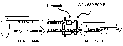
68 to 50 Pin External Converter
In order to go from a 68-pin external connection to a 50-pin external
connection, all that is required is termination of the High Byte.

An important consideration should be kept in mind when using an external
converter.
* As drawn above, only 8-bit devices should be used to the right of the
converter.
Warning! 68-pin to 50-pin external converters are
available from other manufacturers, but only converters that actively terminate
the High Byte should be used. 68-pin to 50-pin cables are also available
through other manufacturers, but most of these cables do not terminate the High
Byte, and should therefore not be used.
Ed. The availability of C68 to HPDB68 cables
makes this a "nice to know".
68 to 50 Pin Internal Converter
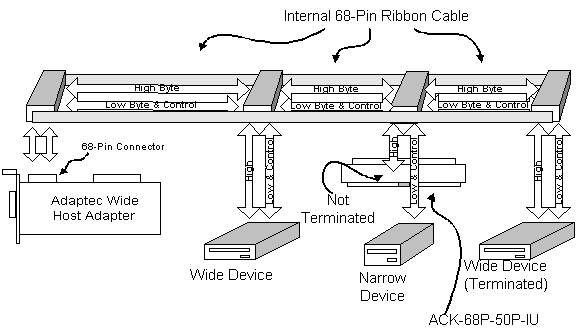
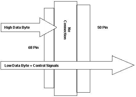
An internal converter converts a 68-pin ribbon cable connector to a 50-pin
connector. They block the High Byte, but does not terminate it, because one of
the rules of SCSI states that termination may only occur at the end of the
bus1. The High Byte is blocked and only the Low Byte and Control signals are
fed through the converter.

Data Flow for 68 to 50 Pin Converter

The following considerations should be kept in mind when using an internal
converter:
- Internal converters can be used anywhere along the ribbon cable except on
the last connector.
- When an internal converter is used, the last device along the ribbon cable
must be a wide device that is terminated (Example
3 below) or you must use a ribbon cable that has terminator built into its
end (ACK-W2W-5IT) (Example 4 below).
- Several internal converters can be used along a ribbon cable.
- Other connectors along the ribbon cable that are not connected to an
internal converter should be used only with wide devices or remain unused.
Warning! Internal converters that terminate the
High Byte are available from other manufacturers and are useful if the last
device must be a narrow device. This type of converter can not be used in the
middle of the bus.
The following are examples of how to connect a SCSI bus
with wide and narrow devices. These examples refer to both the Corvette
and Corvette Turbo. They MIGHT possibly apply
to the Cheetah and Passplay adapters. The SCSI adapter automatically terminates
it's end of the bus, but you must manually set termination of the "High
Data Byte" - IF - a Wide device is attached
to the 50 pin edgecard - OR - for some odd
reason, you have a wide device on a 50 pin cable attached to the Wide internal
conductor.
Ed. though I have a vivid
imagination, the only plausible way is using a 68 to 50 pin adapter from
a 9585-K/N, then a narrow cable to a Wide device.
External Devices
Example 1 (Mixed External)

In this configuration, set "Wide SCSI messages
- External" to Enabled. Set "Fast
SCSI - External"
to Enabled BUT
keep in mind:
- One IBM SCSI device enclosure model 3511.
- Up to three external SCSI device enclosures model 3510.
- Any external configuration where the SCSI cable length does not exceed 3
meters.
- Ed. Some older SCSI devices may not support
"Fast" (10MHz rate). If there are lots of errors, or it takes longer than
normal to use the device, you may fix the problem by setting
"Fast SCSI External" to
Disabled.This will force all devices on the
external port to 5MHz, INCLUDING the wide device.
Example 2 (External Narrow Devices Only)

In this configuration, "Wide SCSI messages -
External" can be set to Enabled or
Disabled. You can choose to enable or disable Wide
Messages, because the device and the adapter can properly negotiate and support
narrow transfers. "Fast SCSI - External" should be
enabled if the devices can support the Fast SCSI (10MHz rate).
Internal Devices
Example 3 (Mixed Internal, Wide Last)

In this configuration, set "Wide SCSI messages
- Internal" to Enabled. In this example,
the last wide device has termination enabled.
Example 4 (Mixed Internal, Narrow Last)

In this configuration, set "Wide SCSI messages -
Internal" to Enabled. The 68 pin cable
allows the wide device and the adapter to properly negotiate and support wide
transfers. In this example, there is a wide (16-bit) terminator on the cable
after the narrow device.
Internal and External Devices
Example 5 (Mixed External and Mixed Internal)

In this configuration, you have to consider the data width (Wide - Narrow)
and the speed of the external bus (Fast Enabled/Disabled).
Connecting All Three Ports of Corvette/Turbo Corvette
Caution! Using both the 50 and 68 pin ports of the
Corvette or Corvette Turbo is not recommended.
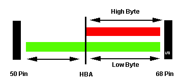
The interior 68 pin SCSI bus on the Corvette can be pictured as two parallel
horizontal lines, the 'upper' eight data bits, and the 'lower' eight data bits.
The lower bus is tapped and routed to the internal 50 pin SCSI edgecard
connector as well.
Using 50 and 68 Pin Internal Ports Simultaneously

Think of the Low Byte (Green) and High Byte (Red) transmission
characteristics. If both connectors are used, the Low Byte transmission path is
not the same length as the High Byte. The narrow device may use the old passive
termination, which is not as precise as the newer active termination. The
narrow cable may have a different impedance as well.
What keeps this bus from hurtling off the edge is that the SCSI devices
negotiate for control of the bus. I have no O scope to view the waveforms, but
if there isn't some reflectance on the low byte, I'd be surprised. My suspicion
is the extra cable length creates "noise" on the SCSI bus that impedes the
negotiation and the data transmission.
Prove me wrong, I look forward to your data.
From other readings, it appears that having Wide messages enabled for a
narrow device on a narrow cable results in no harm no foul, as the adapter and
device negotiate transmission width.
If a wide device on an 8 bit cable is queried by a wide adapter, they will
negotiate for a wide transfer. So in this case, the operator MUST force the
transfer to 8 bit by using Wide Messages - Disabled.
The autotermination pays no mind to the wide enabled or disabled settings.
It responds only to the presence or absence of a device... This maintains the
point-to-point requirement of the SCSI bus.
|