|
40-Pin Card-Edge Interface
34-pin Header Interface
Enhanced 34-pin Header Interface (Media Sense)
40-pin Planar Interface (8555)
40-pin Planar Interface (Media-Sense) (95 XP)
44-pin Planar Interface (Media-Sense) (95A, Lacuna, 85 K/N)
Content created by Tomáš Slavotínek and Louis Ohland. Sources linked down
below.
PS/2 Floppy Drive Connectors
Signals and voltages are transferred between the system board and the
diskette drives by a cable or printed circuit board. The printed-circuit board
provides a 2- by 20-pin card edge connector for each diskette drive, with a
locator key between pins 34 and 36. The cable interface provides a 2 x 17-pin
header connector to each diskette drive, with a locator key below pin 17. The
following tables show the signals and DC voltages for each diskette drive
connector type.
Extracted from PS/2
3.5-inch Diskette Drives Technical Reference (S42G-2194-00), 2nd Ed., Oct
1992, pages 10-12. (Unless noted otherwise.)
Note: There are differences between the 1990 Tech
Ref and the '92 Tech Ref Signal names for the Enhanced 34-pin interface. See
the Notes below the table. I believe the additional definition is related to
the floppy controller used for the EE floppies.
40-Pin Card-Edge Interface
| Pin | Signal | Pin | Signal |
|---|
| 1 | Ground | 2 | -High Density Select |
| 3 | Reserved | 4 | Reserved |
| 5 | Ground | 6 | Reserved |
| 7 | Ground | 8 | -Index |
| 9 | Ground | 10 | Reserved |
| 11 | Ground | 12 | -Drive Select |
| 13 | Ground | 14 | Reserved |
| 15 | Ground | 16 | -Motor Enable |
| 17 | Ground | 18 | -Direction In |
| 19 | Ground | 20 | -Step |
| 21 | Ground | 22 | -Write Data |
| 23 | Ground | 24 | -Write Enable |
| 25 | Ground | 26 | -Track 0 |
| 27 | Ground | 26 | -Write Protect |
| 29 | Ground | 30 | -Read Data |
| 31 | Ground | 32 | -Head 1 Select |
| 33 | Ground | 34 | -Diskette Change |
| 35 | Ground | 36 | Ground |
| 37 | Ground | 36 | +5 Vdc |
| 39 | Ground | 40 | +12 Vdc |
34-pin Header Interface
This connector is for drives and controllers that do not support media sense.
| Pin | Signal | Pin | Signal |
|---|
| 1 | Ground | 2 | -High Density Select |
| 3 | +5 Vdc | 4 | Drive Type ID 1 |
| 5 | Ground | 6 | +12 Vdc |
| 7 | Ground | 8 | -Index |
| 9 | Ground | 10 | Reserved |
| 11 | Ground | 12 | -Drive Select |
| 13 | Ground | 14 | Reserved |
| 15 | Ground | 16 | -Motor Enable |
| 17 | Ground | 18 | -Direction In |
| 19 | Ground | 20 | -Step |
| 21 | Ground | 22 | -Write Data |
| 23 | Ground | 24 | -Write Enable |
| 25 | Ground | 26 | -Track 0 |
| 27 | Ground | 28 | -Write Protect |
| 29 | Ground | 30 | -Read Data |
| 31 | Ground | 32 | -Head 1 Select |
| 33 | Ground | 34 | -Diskette Change |
Enhanced 34-pin Header Interface (Media Sense)
This connector is for drives and controllers that support media sense.
| Pin | Signal | Pin | Signal |
|---|
| 1 | Ground | 2 | Data rate Select 1 |
| 3 | +5 Vdc | 4 | Drive Type ID1/Drive status 1 |
| 5 | Ground | 6 | +12 Vdc |
| 7 | Ground | 8 | -Index |
| 9 | Drive Type ID0/Drive status 0 | 10 | Reserved |
| 11 | Ground | 12 | -Drive Select |
| 13 | Ground | 14 | -Security Command * |
| 15 | Ground | 16 | -Motor Enable |
| 17 | Media Type ID1/Drive status 3 | 18 | -Direction In |
| 19 | Ground | 20 | -Step |
| 21 | Ground | 22 | -Write Data |
| 23 | Ground | 24 | -Write Enable |
| 25 | Ground | 26 | -Track 0 |
| 27 | Media Type ID0/Drive status 2 | 28 | -Write Protect |
| 29 | Ground | 30 | -Read Data |
| 31 | Ground | 32 | -Head 1 Select |
| 33 | Data rate Select 0 | 34 | -Diskette Change |
All blue text is not present in '90 Tech. Ref.
* Not supported by all drives or all systems.
'90 Tech. Ref. has this Reserved.
40-pin Planar Diskette Interface (8555)
| Pin | Signal | Pin | Signal |
|---|
| 1 | Reserved | 2 | -High Density Select |
| 3 | +5 Vdc | 4 | Reserved |
| 5 | Ground | 6 | +12 Vdc |
| 7 | Ground | 8 | -Index |
| 9 | Ground | 10 | Reserved |
| 11 | Ground | 12 | -Drive Select |
| 13 | Ground | 14 | Reserved |
| 15 | Ground | 16 | -Motor Enable |
| 17 | Ground | 18 | -Direction |
| 19 | Ground | 20 | -Step |
| 21 | Ground | 22 | -Write Data |
| 23 | Ground | 24 | -Write Enable |
| 25 | Ground | 26 | -Track 0 |
| 27 | Ground | 28 | -Write Protect |
| 29 | Ground | 30 | -Read Data |
| 31 | Ground | 32 | -Head 1 Select |
| 33 | Ground | 34 | -Diskette Change |
| 35 | Ground | 36 | Ground |
| 37 | Reserved | 38 | +5 Vdc |
| 39 | Ground | 40 | + 12 Vdc |
Information extracted from IBM PS/2 Model 55 SX Technical Reference,
Type 9595, page 2-8, Figure 3-5.
40-pin Planar Diskette Interface (Media-Sense)
This connector is found on the 90 XP and 95 XP planars.
| Pin | Signal | Pin | Signal |
|---|
| 1 | -2nd Drive installed [D0 & D1 pin 1] | 2 | Data rate Select 1 |
| 3 | +5 Vdc | 4 | Drive Type ID1 |
| 5 | Ground | 6 | +12 Vdc |
| 7 | Ground | 8 | -Index |
| 9 | Drive Type ID0 | 10 | -Motor Enable 1 [D0 pin 16] |
| 11 | Ground | 12 | -Drive Select 0 [D1 pin 12] |
| 13 | Ground | 14 | -Drive Select 1 [D0 pin 12] |
| 15 | Ground | 16 | -Motor Enable 0 [D1 pin 16] |
| 17 | Media Type ID1 | 18 | -Direction In |
| 19 | Ground | 20 | -Step |
| 21 | Ground | 22 | -Write Data |
| 23 | Ground | 24 | -Write Enable |
| 25 | Ground | 26 | -Track 0 |
| 27 | Media Type ID0 | 28 | -Write Protect |
| 29 | Ground | 30 | -Read Data |
| 31 | Ground | 32 | -Head 1 Select |
| 33 | Data rate Select 0 | 34 | -Diskette Change |
| 35 | Ground | 36 | Drive Select 2 [D2 pin 12] |
| 37 | Ground | 38 | Ground |
| 39 | Ground | 40 | -Motor Enable 2 [D2 pin 16] |
Signals not intended for all drives are marked as such by a note in
[square brackets].
Information not available in any tech. reference I have access to. So I
have used the known 34-pin floppy drive pinout, the actual 40-pin 95 XP floppy
cable, and some measurement results to figure this out.
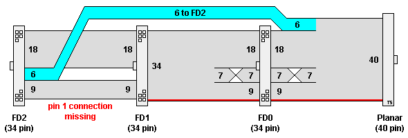
40-pin Floppy Cable Wiring Diagram (Model 95 XP, FRU P/N 33F8430)

| Planar | FD0 | FD1 | FD2 |
|---|
| 1 | 1 | 1 | — |
| 2-9 | 2-9 | 2-9 | 2-9 |
| 10 | 16 | 10 | 10 |
| 11 | 15 | 11 | — |
| 12 | 14 | 12 | — |
| 13 | 13 | 13 | — |
| 14 | 12 | 14 | — |
| 15 | 11 | 15 | — |
| 16 | 10 | 16 | — |
| 17-34 | 17-34 | 17-34 | 17-34 |
| 35-40 | — | — | 11-16 |
44-pin Planar Diskette Interface (Media-Sense)
This connector is found on the 95A, Bermuda, Lacuna, 85 X, and 85 K/N planars.
All floppy drives used must support media sense.
| Pin | Signal | Pin | Signal |
|---|
| 1 | -2nd Drive installed [D0 & D1 pin 1] | 2 | Data rate Select 1 |
| 3 | +5 Vdc | 4 | Drive Type ID1/Drive status 1 |
| 5 | Ground | 6 | +12 Vdc |
| 7 | Ground | 8 | -Index |
| 9 | Drive Type ID0/Drive status 0 | 10 | Reserved |
| 11 | Ground | 12 | -Drive Select 0 [D0 pin 12] |
| 13 | Ground | 14 | -Security Command 0 [D0 pin 14] |
| 15 | Ground | 16 | -Motor Enable 0 [D0 pin 16] |
| 17 | Media Type ID1/Drive status 3 | 18 | -Direction In |
| 19 | Ground | 20 | -Step |
| 21 | Ground | 22 | -Write Data |
| 23 | Ground | 24 | -Write Enable |
| 25 | Ground | 26 | -Track 0 |
| 27 | Media Type ID0/Drive status 2 | 28 | -Write Protect |
| 29 | Ground | 30 | -Read Data |
| 31 | Ground | 32 | -Head 1 Select |
| 33 | Data rate Select 0 | 34 | -Diskette Change |
| 35 | Drive Select 1 [D1 pin 12] | 36 | Ground |
| 37 | -Security Command 1 [D1 pin 14] | 38 | Ground |
| 39 | -Motor Enable 1 [D1 pin 16] | 40 | -Drive Select 2 [D2 pin 12] |
| 41 | Ground | 42 | -Security Command 2 [D2 pin 14] |
| 43 | Ground | 44 | -Motor Enable 2 [D2 pin 16] |
Signals not intended for all drives are marked as such by a note in
[square brackets].
Information extracted from IBM PS/2 Servers 95 and 95A Technical Reference,
Type 9595, page 2-5, First Ed., Sept 1993. P/N 71G3726
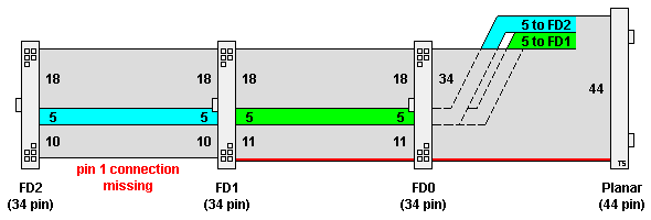
44-pin Floppy Cable Wiring Diagram (Model 95A, FRU P/N 92F0283)

| Planar | FD0 | FD1 | FD2 |
|---|
| 1 | 1 | 1 | — |
| 2-11 | 2-11 | 2-11 | 2-11 |
| 12-16 | 12-16 | — | — |
| 17-34 | 17-34 | 17-34 | 17-34 |
| 35-39 | — | 12-16 | — |
| 40-44 | — | — | 12-16 |
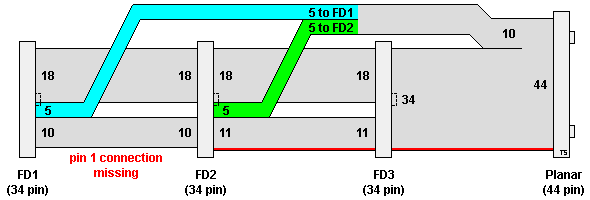
44-pin Floppy Cable Wiring Diagram (Bermuda, FRU P/N 96F7756, P/N 41G9205)
This cable is electrically equivalent to the 95A cable but the physical
construction is different (connector orientation and cable structure).

| Planar | FD3 | FD2 | FD1 |
|---|
| 1 | 1 | 1 | — |
| 2-11 | 2-11 | 2-11 | 2-11 |
| 12-16 | 12-16 | — | — |
| 17-34 | 17-34 | 17-34 | 17-34 |
| 35-39 | — | 12-16 | — |
| 40-44 | — | — | 12-16 |
|