|
Selected papers from: IBM RISC System/6000 Technology: Volume II 23 Sep 1993
Page 84-87: "Micro Channel Features" by Dan M. Neal and James O. Nicholson
Introduction
The IBM Micro Channel interface is a general purpose computer interface
intended to support the use of I/O and feature cards in electronic data
processing equipment. It was originally introduced with the
IBM Personal System/2 series of products and is
also utilized in the IBM RISC System/6000 (RS/6000),
other IBM products, and other manufacturers' product lines.
The Micro Channel bus has been designed to allow use across a broad product
spectrum. Enhanced features of the Micro Channel architecture provide higher
levels of performance and error reporting and are fully compatible with the
base Micro Channel architecture. This article describes those features
supported on the RISC System/6000 family of products. These include:
- Streaming Data procedure (32-bit and 64-bit at 10 MHz)
- Address and data parity Synchronous exception signaling
Streaming Data Procedure
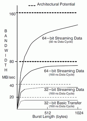
Streaming Data is a procedure that provides the ability to transfer multiple
data cycles within one bus envelope. The Streaming Data procedure amortizes
device selection overhead across the total packet, significantly increasing the
performance capability of the Micro Channel bus. Sustainable performance is a
function of the total packet length and is illustrated in Figure 1.

Figure 1. Streaming Data Performance Improvements
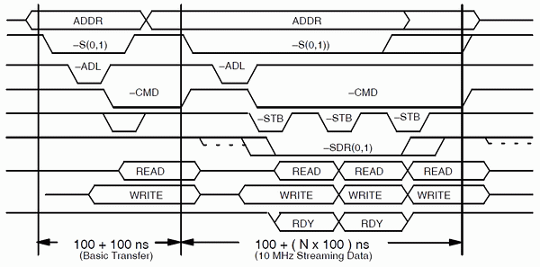
Figure 2 illustrates the procedures used in basic transfer and 10 MHz
streaming data cycles. A basic transfer cycle is initiated by a bus master
placing an address on the bus, and then activating one of the status signals,
-S(0,1). A typical bus master will allow 100 ns for device selection, then
activate the command (-CMD) signal for 100 ns to control the data transfer. A
streaming data cycle is similar, but instead of a word of data, a block of data
is transferred while the -CMD signal is active. The address specifies only the
starting address of the block.

Figure 2. 16/32-bit, Basic Transfer and 10 MHz Streaming Data
Streaming Data Request (SDR)
Three signals, streaming data request 0 and 1 (-SDR (0,1)) and streaming
data strobe -SD_STROBE (-STB), mediate 16-bit and 32-bit streaming data cycles.
The -SDR (0,1) signals are driven by the bus slave following activation of the
address data latch (-ADL) signal to indicate that it supports streaming data.
The -STB signal is driven by the bus master and serves as a bus clock
delimiting words in the data transfer. Each negative transition of the -STB
signal defines a new word. The -SDR(0,1) and -STB signals use tri-state drivers
and require resistive pullups on card inputs to hold the signals high when not
being driven. At the end of a streaming data cycle, the deactivation of the
-CMD signal serves as the last bus clock.
The -SDR(0,1) signals are coded to indicate the performance capabilities of
the slave. This information is used by the bus master for speed matching to
ensure that it does not exceed the maximum clocking rates of the slave. A
master can perform streaming data transfers at 10 MHz when -SDR(0,1) is a
binary 00, 01, or 10. A master can perform streaming data transfers at 20 MHz
when -SDR(0,1) is a binary 00 or 10. The valid streaming data signal
combinations from the selected slave are shown in Table 1.
| SDR | Resulting Cycle |
|---|
| 0 | 1 |
|---|
| 1 | 1 | Basic Transfer Cycle |
| 0 | 1 | 10 MHz Max (100 ns Min Cycle) |
| 0 | 0 | 20 MHz Max (50 ns Min Cycle) |
| 1 | 0 | Reserved |
Table 1. Code Points for -SDR(0,1) Signals
(Ed. see also HERE)
At 10 MHz, the period of the -STB clock signal is 100 ns minimum. At 20 MHz,
the period of the -STB clock signal is 50 ns minimum. The streaming data
procedures are fully downward compatible. Masters and slaves that support 20
MHz streaming data must also support 10 MHz streaming data and Basic transfers.
Likewise, Masters and slaves that support 10 MHz streaming data must also
support Basic Transfers. The -SDR(0,1) signals do not have to be valid for a
bus master to indicate streaming data support. Instead, a bus master normally
activates the -STB signal concurrently with the -CMD signal and samples the
-SDR(0,1) signals just before the deactivation of the -STB signal. If the
-SDR(0,1) signals are not active at that time, the bus master deactivates the
-S(0,1) signals and completes the cycle as a basic transfer. This provides
relaxed timing requirements for the -SDR(0,1) signals.
The Streaming Data procedure for 16-bit and 32-bit transfers includes
synchronous data pacing using the card channel ready (CD_CHRDY) and channel
ready return (CHRDYRTN) signals. The slave indicates that it is not ready to
complete a particular data cycle by activating the CD_CHRDY signal (RDY) after
the -STB signal is activated. This is propagated to the CHRDYRTN signal by a
logical AND operation on the system planar for sampling by the bus master. The
bus master is required to repeat the data cycle if the CHRDYRTN signal is
inactive (low) on the next transition of the -STB signal. The -STB signal must
continue cycling until the slave activates the CD_CHRDY signal.
Termination controls are symmetric so that either the bus master or slave
can end a streaming data cycle. The procedure is synchronous and is illustrated
in Figure 3 for 10 MHz streaming data transfers.

Figure 3. Streaming Data Termination (10 MHz)
Bus masters request termination by synchronously deactivating the -S(0,1)
signal coincident with activation of the -STB signal, while slaves request
termination by synchronously deactivating the -SDR(0,1) signals following the
activation of the -STB signal. Bus masters should not terminate the cycle until
the -SDR(0,1) signals are deactivated. If a slave is not ready when a master
deactivates the -S(0,1) signal, the slave should set the CD_CHRDY signal low
and hold the -SDR(0,1) signals active until the cycle in which the CD_CHRDY
signal will be set high. Although not illustrated, the architecture also
supports the ability to defer initiation of streaming data cycles using the
CD_CHRDY signal.
The termination procedures for 10 MHz and 20 MHz streaming data transfers
are similar, but have differences. The primary difference is that the request
for termination occurs on the data transfer before the desired stopping point
for 10 MHz streaming data, while the termination request occurs on the
next-to-last negative transition of -STB for 20 MHz streaming data transfers.
For more detail on streaming data termination, the reader should refer to the
Micro Channel architecture specification [1].
For compatibility reasons, all 16-bit and 32-bit streaming data cycles must
be initiated on 4-byte address boundaries. This is because the Micro Channel
architecture includes a byte-steering function to facilitate transfers between
16-bit bus masters and 32-bit bus slaves. This steering function is latched at
the time the -CMD signal is activated and remains static throughout the data
transfer envelope. As such, it would not properly steer the data when operating
with 16-bit streaming masters. Specifying streaming data to begin on 4-byte
address boundaries disables the steering controls, but results in the
requirement that 32-bit slaves provide their own byte steering when engaged in
data streaming operations with 16-bit masters.
Another streaming data capability includes use of the address bus to
transfer data. Since only a single address cycle is provided by the master
during a streaming data operation, the address bus can be made available
(multiplexed) during the data portion of the cycle to transfer data. This
allows a "doubling" of the available bandwidth by transferring 64-bits of data
each data cycle instead of only 32-bits. An additional Streaming Data signal is
used to indicate that the operation will include 64-bit data transfers,
"Multiplexed Streaming Data Request" (-MSDR). This signal is driven by the
slave to indicate to the controlling master that it supports 64-bit streaming
data transfers.
The 64-bit streaming data transfers can only be performed between 64-bit
streaming masters and 64-bit streaming data slaves. A 64-bit streaming data
cycle is initiated as a 32-bit basic transfer cycle, and all the rules
associated with this procedure applies. The selected slave activates -MSDR to
indicate that it supports 64-bit streaming data operations. The data rate
requested by the slave is indicated by -SDR(0,1). The -BE(0-3) signals are
driven inactive by the master to indicate a 64-bit streaming data procedure
will be used. During the transfer to the slave, the master starts -STB and
gates the data onto the data and address buses. During a transfer to the
master, the master tri-states the address bus after activating -CMD, and, after
the trailing edge of -BE(0-3), the slave gates the data onto the data and
address buses.
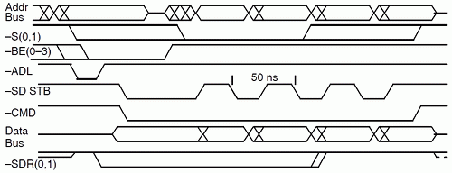
If 20 MHz streaming data is supported by both the master and the slave, both
must execute at least 4 streaming data "data cycles". The master indicates 20
MHz streaming data transfers by driving the second Status line active. Figure 4
illustrates the 20 MHz streaming data procedure with 64-bit transfers. 20 MHz
streaming data is currently not supported in the RS/6000 Systems.

Figure 4. 64-bit 20 MHz Streaming Data Overview
Though a slave may delay the start of streaming data transfers using the
CD_CHRDY signal, data pacing is not supported during 64-bit streaming data
operations, and is not supported during 20 MHz streaming data operations.
Address and Data Parity
Address and Data Parity are provided to improve error detection
characteristics of the Micro Channel architecture. These mechanisms are
particularly well suited to detecting typical errors such as card-seating
problems and electromagnetic interference.
Address parity and data parity support are optional and independent, and
mixtures of parity and non-parity devices are permitted. Address parity
is controlled by a signal driven by the bus master called address parity enable
(-APAREN). Normally, a slave device responds to a valid address by activating
the card selected feedback (-CD_SFDBK) signal. If the -APAREN signal is active,
all slave devices supporting address parity check address parity and, if
incorrect, activate the channel check (-CHCK) signal as described in
"Synchronous Exception Signaling." A slave should not become selected or
activate the -CD SFDBK signal if address parity is incorrect and should not set
any internal error status as the error may not have affected it. The bus master
is then expected to suspend operations, set internal error status indicating
that a -CHCK occurred with no -SFDRKRTN signal, and interrupt the system.
Data parity checking is controlled by the data parity enable (-DPAREN)
signal. If a parity error is detected during a write operation, and the -DPAREN
signal is active, slave devices supporting data parity activate the -CHCK
signal as described in "Synchronous Exception Signaling". If the bus master
detects a read data parity error and the -DPAREN signal is active, it is
expected to suspend operations, set internal error status indicating that a
read parity error occurred, and interrupt the system.
Synchronous Exception Signaling
The Micro Channel architecture provides for exception signaling with the
-CHCK signal. Initial use of the -CHCK signal was asynchronous in the Personal
System/2 products. The use of the -CHCK signal was enhanced to support the
signaling of synchronous events such as page faults, write parity errors, and
command queue overflows. Synchronous exception signaling simply allows the
pulsing of the -CHCK signal in the same bus cycle that caused the exception.
This feature is key to meeting system data integrity and error recovery
requirements of the RS/6000 system.
Conclusion
Three features of the Micro Channel architecture have been discussed. These
features: increasing the "peak" bandwidth capabilities first from 20M bytes/sec
to 40M bytes/sec, then to 80M bytes/sec, and most recently to 160M bytes/sec;
addition of parity checking as an optional feature; and support of synchronous
exception signaling, broaden the characteristics of that bus to support
advanced I/0 devices or systems. These features retain compatibility with
existing card and planar board designs. These features are implemented in the
RS/6000 family of products and are key factors in meeting the performance, data
integrity, and error recovery goals of that system.
Acknowledgments
The Micro Channel architecture was jointly developed with Boca Raton
architecture and
various product development groups worldwide. B.M. Bass,
D.M. Desai, J.K. Langgood, S. Dhawan, R.A. Kelley, L.F. McDermott, D.M. Neal,
J.O. Nicholson, J.D. Reid, F.E. Strietelmeier, J.D. Touchton, R.K. Arimilli,
D.W. Siegel, and L.P. Vergari provided substantial contribution to the Micro
Channel features described in this article and their contributions are
appreciated.
References
1. IBM Personal System/2 Hardware Interface
Technical Reference - Architectures Manual, IBM Corporation.
|