|
Author: Richard Wilton
Source: Inside the IBM PCs - BYTE 1987 Extra Edition,
page 67-72 (local copy)
Note: Pages 67-72 focus on the Multi-Color
Graphics Array (MCGA). The VGA portion of the article begins on Page 72 and
ends on Page 80. IMHO, there is more VGA programming stuff than you can shake a
stick at, while MCGA doesn’t get much love. All typos are just that (I type
out of self defense). -LFO
The IBM PS/2 series introduces two new video subsystems, the Multi-Color Graphics Array (MCGA) and Video Graphics Array
(VGA). This article is an overview of the MCGA and the VGA from a programmer's
point of view. If you are already familiar with older video adapters, such as
the CGA, EGA, or Hercules cards, this article will point out the similarities
and differences between the PS/2 video subsystems and previous IBM video
adapters. If you are new to video hardware programming, you can use the
examples in this article as a focus for further exploration of the PS/2
hardware.
Unlike the IBM PC, XT, and·AT, into which you must install a separate card
that supports the necessary hardware to drive a video display, all the PS/2s
are equipped with a built-in video subsystem on the motherboard. The Model 30
comes with the MCGA, while the Models 50, 60, and 80 use the VGA.
For compatibility (and, no doubt, in hopes of selling lots of hardware), IBM
also offers a VGA adapter that implements the VGA subsystem on a card for the
XT, AT, or PS/2 Model 30.
Monitors
The MCGA and VGA differ from previous IBM video adapters in that both
require that you use an analog monitor instead of a digital monitor. Adapters
such as the CGA and the EGA use digital monitors in which the RGB color signals
generated by the adapter are digital signals (on or off). This limits the
number of different colors that the subsystem can display. For example, IBM's
enhanced color display, which is driven by six RGB signals as generated by an
EGA, can display a total of 64 (26) different colors. In contrast, the
PS/2-compatible monitors use RGB signals with voltage levels that are
continuously variable instead of simply on or off. Because the displayed
brightness of a color corresponds to the voltage level of the color drive
signals, an analog monitor can display a much larger variety of colors.
IBM offers one monochrome and two color monitors for use with the MCGA and
the VGA. You can use a monochrome or color monitor with either video subsystem.
You can also use EGA-compatible monitors with analog capability, such as the
NEC MultiSync and Sony MultiScan monitors, with the MCGA and VGA.
Compatibility
Programs that run on the CGA can run unchanged on the MCGA, even if they
bypass the video BIOS and program the hardware directly. Also, because the PS/2
Model 30 has a PC-compatible bus, a monochrome display adapter or Hercules
adapter can coexist with the MCGA in the PS/2 Model 30.
The VGA is similar in its programming interface to the EGA. Its control
ports and buffer addressing are EGA compatible, so programs that run on an EGA
generally run on a VGA as well. The VGA is compatible enough with the EGA at
the hardware level that the VGA can usually run ill behaved programs that
access the EGA control registers directly.
From a programmer's perspective, there is not much resemblance between the
MCGA and the VGA. The I/O port assignments in the MCGA and VGA differ
significantly. So does the layout of video RAM in the two subsystems. A program
that bypasses the video BIOS to control the hardware directly will probably not
run on both the MCGA and the VGA unless it contains special code for
programming each subsystem independently.
Documentation
The programming interface to PS/2 video hardware is documented in the IBM
technical reference manuals for the Models 30, 50, and 60. The video BIOS is
covered by a separate set of IBM reference manuals, the Personal System/2 and
Personal Computer BIOS Interface Technical Reference. Obviously, this article
does not cover all the details of the video hardware implementation. If you
need to understand the hardware or firmware in detail, you should obtain the
appropriate IBM technical manuals.
The MCGA
The heart of the MCGA circuitry lies in two proprietary gate arrays: the
memory-controller gate array, which incorporates the functions of a CRT
controller, and the video-formatter gate array, which controls video mode
selection and color-attribute decoding.
| Reg. |
Function |
| 0 |
Horizontal total |
| 1 |
Horizontal displayed |
| 2 |
Start horizontal sync |
| 3 |
Sync pulse width |
| 4 |
Vertical total |
| 5 |
Vertical total adjust |
| 6 |
Vertical displayed |
| 7 |
Start vertical sync |
| 8 |
(Reserved) |
| 9 |
Scan lines per character |
| 0A |
Cursor start |
| 0B |
Cursor end |
| 0C |
Start address high |
| 0D |
Start address low |
| 0E |
Cursor location high |
| 0F |
Cursor location low |
| 10 |
Mode control |
| 11 |
Interrupt control |
| 12 |
Character generator, sync polarity |
| 13 |
Character-generator pointer |
| 14 |
Character-generator count |
Table 1: MCGA memory-controller registers.
Registers 0 through 0F hexadecimal are comparable to those in the CGA 's CRT
controller
You can program the memory controller through a set of 8-bit registers (see
Table 1) mapped to I/O ports 3D4 and 3D5 hexadecimal. (Ed. For the remainder of this article, addresses will be
in hexadecimal.) As on the CGA, you access the registers by first writing the
register number to the port at 3D4, and then writing or reading the specified
register at 3D5. Unlike the CGA, however, you can read and write all the memory
controller registers. This is a handy feature if you are debugging programs,
although it's not a good idea to rely on it if you are concerned about
maintaining CGA compatibility.
The first 16 memory-controller registers are analogs of the registers on the
Motorola 6845, the CRT controller chip used in the CGA. This means that CGA
compatible programs that access these registers directly can also run on the
MCGA. Because the default horizontal and vertical CRT timing parameters used on
the MCGA differ from those used on the CGA, you might want to write-protect the
first seven registers so that CGA compatible programs that attempt to update
these registers do not inadvertently disrupt crucial CRT timing signals. Bit 7
of the mode-control register (register 10h) is the write-protect bit for the
timing registers.
The remaining memory-controller registers control video mode selection and
the alphanumeric character generator. These registers do not exist on the CGA.
They support functions that are similar to what is available on the VGA:
additional graphics modes and RAM-loadable alphanumeric character sets.
The video formatter supports three CGA-compatible control registers. The
mode-control register (I/O port 3D8) controls video mode selection. The
color-control register (port 3D9) controls palette and graphics mode
background-color selection. The status register (port 3DA) is a read-only
register whose contents indicate the status of the CRT's horizontal and
vertical timing signals. All three of these registers are compatible with the
analogous registers on the CGA.
In addition to the six video modes supported by the CGA, the MCGA offers a
640 by 480 two-color graphics mode (video BIOS mode llH) and a 320 by 200
256-color graphics mode (BIOS mode 13H). You can set up both new modes, as well
as all the CGA-compatible modes using INT l0h function 0 (see Listing
1).
mov   ah,0                ; AH = INT 10h function #
mov   al, VideoModeNumber ; AL = 11h (640x480 two-color)
                          ; 12h (640x480 16-color)
                          ; 13h (320x200 256-color)
int   10h                 ; Call video BIOS
Listing 1: Video mode selection using the video BIOS.
New Features
Two features of the MCGA are of special interest to programmers. One is that
the vertical resolution of both alphanumeric and graphics modes is greater than
on previous IBM video adapters. The other is that the MCGA can display up to
256 different colors at one time out of a possible 262,144 (256K) colors.
| Mode # |
Description |
MCGA |
VGA |
| 0 |
40 by 25 16-color alphanumeric
(320 by 400 resolution) |
X |
|
| 0 |
40 by 25 16-color alphanumeric
(360 by 400 resolution) |
|
X |
| 2 |
80 by 25 16-color alphanumeric
(640 by 400 resolution) |
X |
|
| 2 |
80 by 25 16-color alphanumeric
(720 by 400 resolution) |
|
X |
| 11H |
640 by 480 two-color graphics |
X |
X |
| 12H |
640 by 480 16-color graphics |
|
X |
| 13H |
320 by 200 256-color graphics |
X |
X |
Table 2: New BIOS video modes on the MCGA and VGA
The vertical resolutions of the default BIOS video modes are listed in
Table 2. In alphanumeric modes, the vertical resolution is 400 scan
lines-twice that of the CGA and better than the EGA's 350-line "enhanced"
modes. Since the BIOS still displays 25 rows of characters in alphanumeric
modes, the vertical size of each displayed character is 16 scan lines. These
higher-resolution characters are sharp and easy to read.
When the MCGA emulates the CGA graphics modes (640 by 200 two-color and 320
by 200 four-color), it doubles the vertical size of pixels so that each is two
scan lines high. Thus, although the CGA compatible graphics modes use the same
resolution in terms of pixels, the displayed resolution is still 400 lines, so
these modes have a sharper appearance on the MCGA than they do on a CGA.
Another feature of both the MCGA and the VGA is expanded color display
capability. This is provided by a digital-to-analog converter (DAC) that
generates the analog RGB signals used to drive the PS/2 monochrome and color
monitors. (The monochrome monitor responds only to the green color signal; the
color monitors recognize all three.)
The video DAC uses a set of 256 eighteen-bit internal registers, each of
which specifies an RGB combination. Each of the three primary colors is
allotted 6 bits of each color register; the DAC converts each 6-bit value to a
corresponding analog voltage level in the signals it outputs to the monitor.
Thus, the video DAC can produce any of 64, color intensities for each of the
three primary colors in a color register, thereby generating 256K
(643) color combinations. Since there are 256 video DAC color
registers, the video subsystem can display any 256 of the 256K color
possibilities at one time.
Video BIOS
The video BIOS on the Model 30 provides the same set of functions as the
motherboard ROM BIOS on the PC. The programming interface is the same: You
access all video BIOS functions through interrupt l0h and pass parameters to
the BIOS routines in the CPU's registers.
| Function 10h: Color-palette interface |
| AL=3 |
Toggle alphanumeric intensity/blink state |
| AL=7 |
Read individual palette register (VGA only) |
| AL=8 |
Read overscan (border color) register (VGA only) |
| AL=9 |
Read all palette registers and overscan register (VGA only) |
| AL=10h |
Set individual video DAC color register |
| AL=12h |
Set block of video DAC color registers - |
| AL=13h |
Select video DAC color page (VGA only) |
| AL=15h |
Read individual video DAC color register |
| AL=17h |
Read block of video DAC color registers |
| AL=1Ah |
Read video DAC color-page state (VGA only) |
| AL=1Bh |
Perform gray-scale summing |
| Function 11h: Character-generator interface |
| AL=4 |
Load 8 by 16 alphanumeric characters |
| AL=14h |
Set alphanumeric mode using 8 by 16 characters |
| AL=24h |
Load 8 by 16 graphics characters |
| Function 12h: Alternate select |
| BL=30h |
Select vertical resolution for alphanumeric modes (VGA only) |
| BL=31h |
Enable/disable default palette loading |
| BL=32h |
Enable/disable video addressing |
| BL=33h |
Enable/disable default gray-scale summing |
| BL=34h |
Enable/disable alphanumeric cursor emulation (VGA only) |
| BL=35h |
Display-switch interface |
| Function 1Ah: Display combination code |
| AL=0 |
Read display combination code |
| AL=1 |
Write display combination code |
| Function 1Bh: Functionality/state information |
| Function 1Ch: Save/restore video state (VGA only) |
| AL=0 |
Return state buffer size |
| AL=1 |
Save video state |
| AL=2 |
Restore video state |
Table 3: New INT 10h functions on the MCGA and VGA.
Also, several new INT 10h functions are available in the Model 30, as well
as the other models in the PS/2 series (see Table 3). IBM has expanded
the INT 10h function l0h to provide access to the video DAC color registers.
Function 12h has several new subfunctions that let you vary the default actions
of other BIOS routines. For example, you can call INT 10h function 12h with the
BL register set to 31h to enable or disable default palette loading when the
video mode is changed.
INT 10h functions lAh and lBh are new to the PS/2 series. Your programs can
call these INT 10h functions to determine the state of the video subsystem. A
call to function 1Ah returns the video subsystem's display combination code,
which indicates what type of monitor is in use. Function lBh returns a table
whose contents describe the current state of the video BIOS: the current video
mode, active video page, amount of video RAM available, and so on. These
functions are useful in programs designed to run in more than one video mode,
as well as in pop-up RAM-resident programs that must determine the current
video state to produce appropriate video output.
Alphanumeric-Mode Programming
Despite the MCGA's improved resolution, programming in alphanumeric modes is
virtually the same as on the CGA. The important difference is that the
alphanumeric character generator on the MCGA can display user-defined
characters. (The EGA, VGA, Hercules Graphics Card Plus, and Hercules InColor
Card also have this capability.) The MCGA's alphanumeric character generator
can display characters from any of four different 256-character tables defined
in video RAM.
To make the MCGA's character generator display one of these character sets,
you first load the bit patterns that define the characters into video RAM. Then
you program the character generator to copy the bit patterns from video RAM
into one of its two internal character-definition tables. (These
character-definition tables are called font pages in the IBM technical
literature.)
; load video BIOS 8x8 characters into alphanumeric character generator
mov   ax, 1102h                  ; AH = INT 10h function number
                                 ; AL = 8x8 character-set load
mov   bx, 0                      ; BX = block to load
int   10h                        ; load 8x8 characters into RAM
mov   ax, 1103h                  ; AH = INT 10h function number
                                 ; AL = character-generator load
mov   bx, 0                      ; BX = blocks to load
int   10h                        ; load 8x8 characters into
                                 ; character generator
; program CRT controller to display 8x8 characters
mov   dx, 3D4h                   ; DX = MCGA I/O port address
mov   ax, 309h                   ; AL = 9 (register number)
                                 ; AH = 3 (value for register)
out   dx, ax                     ; update scan-lines register
mov   al, 0Ah                    ; AL = 0Ah (register number)
out   dx, ax                     ; update cursor-start register
mov   al, 0Bh                    ; AL = 0Bh (register number)
out   dx, ax                     ; update cursor-end register
; update status variables in video BIOS data segment
mov   ax, 40h
mov   ds, ax                     ; DS -> video BIOS data segment
mov   word ptr ds:[4Ch], 80*50*2 ; update CRT_LEN
mov   byte ptr ds:[84h], 49      ; update ROWS
mov   word ptr ds:[85h], 8       ; update POINTS
Listing 2: Establishing an 80 by 50 alphanumeric mode on the
MCGA
It is easy to use the MCGA's RAM-loadable character sets on the MCGA to
display characters that are smaller than the default 16-scan-line characters.
In Listing 2, the program calls the video BIOS to load the default
graphics-mode character definitions-in which characters are only eight lines
high-for use by the alphanumeric character generator. The code then reprograms
the MCGA's memory controller to display only eight scan lines in each row of
characters; the result is 50 rows of 80 characters each.
Apart from supporting RAM-loadable character sets, the MCGA replicates
almost all the CGA's capabilities. However, the MCGA is not troubled by
problems with display interference in alphanumeric modes. On the CGA, you must
carefully synchronize CPU accesses to the video RAM with horizontal and
vertical retrace intervals in the display refresh cycle. If you don't, you
might see random patterns of interference or snow on the screen each time a
program accesses the video buffer. The hardware design of the MCGA is such that
this sort of display interference does not occur.
Surprisingly, the MCGA cannot generate a colored border. In alphanumeric
modes on the CGA, you can display a border in any of 16 colors selected by
programming the color-select register (I/O port 3D9). On the MCGA, you can
still program the color-select register, but the MCGA does not display a
border, regardless of the value you store in the register.
Graphics-Mode Programming
In CGA-compatible 640 by 200 two color and 320 by 200 four-color modes, the
MCGA emulates the CGA. The system maps pixels with a two-way interleave in the
video buffer at B800:0000, just as they are mapped on the CGA. Video-buffer
addressing is different, however, in 640 by 480 two-color and 320 by 200
256-color modes.

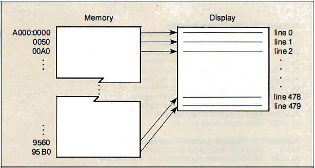
Figure 1: A video-buffer map in 640 by 480 two-color graphics
mode
The video-buffer map in both 640 by 480 two-color and 320 by 200 256-color
modes starts at A000:0000. Both modes map pixels linearly in the buffer from
left to right and from top to bottom on the screen. In 640 by 480 two-color
mode, a bit represents one pixel, so there are eight pixels to each byte in the
video buffer and 80 bytes in the buffer per row of pixels on the screen (see
Figure 1).
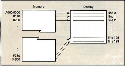
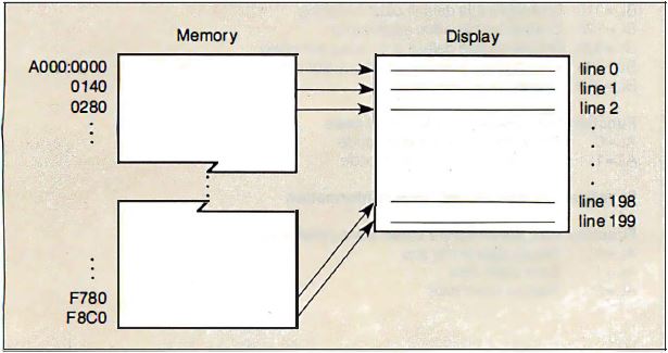
Figure 2: A video-buffer map in 320 by 200 256-color graphics
mode.
In 320 by 200 256-color mode, each pixel value comprises 8 bits, so the
video buffer is mapped as 200 320-byte rows (see Figure 2).
sp13 PROC near
; call with: AX = y coordinate
;            BX = x coordinate
;            CL = pixel value
; compute address of pixel in video buffer
mov   dx,320
mul   dx
add   bx, ax      ; BX = X + 320*Y
mov   ax, 0A000h
mov   ds, ax      ; DS : BX -> pixel in video buffer
; update the pixel value
mov   [bx], cl
ret
sp13 ENDP
Listing 3: Setting the value of a pixel in 320 by 200
256-color mode.
You can write routines that manipulate pixels in these MCGA graphics modes
by modifying code that runs in CGA-compatible graphics modes. The routine in
Listing 3 is an example of code that up-dates a single pixel in 320 by
200 256-color mode. The program computes the video-buffer address by
multiplying the number of pixels in each row by the pixel y coordinate
and then adding the pixel x coordinate. Since each byte in the buffer
represents one pixel, updating a pixel consists of a single machine
instruction.
The MCGA's 640 by 480 two-color graphics mode deserves attention because its
horizontal resolution and vertical resolution are the same in terms of the
number of pixels displayed per inch. (Programmers sometimes describe this
circumstance by saying that the pixels are "square") This means that when you
draw a figure in 640 by 480 graphics mode, you do not need to scale the figure
to accommodate different horizontal and vertical resolutions.
Video DAC Programming
Programming the MCGA's video DAC is straightforward when you use the video
BIOS. In all modes except the 320 by 200 256-color graphics mode, you can use
only the first 16 video DAC registers. The video BIOS loads these registers by
default with a set of 16 CGA-compatible color values. You can, however, update
any of these color registers using any of the 256K color combinations
available.
mov   ah, 10h        ; AH = INT 10h function #
mov   bx, 7          ; BX = 7 (register #)
mov   dh, RedValue   ; DH, CH, CL = 6-bit RGB values
mov   ch, GreenValue
mov   cl, BlueValue
int   10h            ; Call video BIOS
Listing 4: Updating a video DAC color register
For example, Listing 4 shows how you could change the color value in
video DAC register 7. The color-register value is actually 18 bits in size-red,
green, and blue components are each 6 bits. The higher the value you specify
for each component, the higher the displayed intensity of that color.
If a monochrome display is attached to the MCGA, the video BIOS performs a
gray-scaling computation before it loads a color value into the specified video
DAC color register. The video BIOS performs gray-scaling by taking a weighted
average of the red, green, and blue values you specify. (The formula used is 30
percent red + 59 percent green + 11 percent blue.) The result is a gray-scale
value that corresponds to the overall intensity of the specified color
combination.
Richard Wilton (6236 West Sixth St., Los Angeles, CA 90048) is author of
The Programmer's Guide to PC and PS/2 Video Systems; which is due out in
November
|