|
77 System, Front
Ultimedia Module
Ultimedia Module PCB
Ultimedia Module PCB, Top
Ultimedia Module PCB, Bottom
Ultimedia Port
DIY IBM Ultimedia-to-CT 5330
77 Case, Rear
Remove Cover
77 5.25" Drive Bay Guides
Remove Guides
Guide FRUs
Original 5.25" Drive Rail
5.25" 77 Drive Rail Hack
9577 Drive Slide
9577 Air Baffle for Fixed Disk Drive Bay 4C
Air Baffle Pasteboard Hack
77 Case, Front (40, 57 similar) Multimedia Model shown
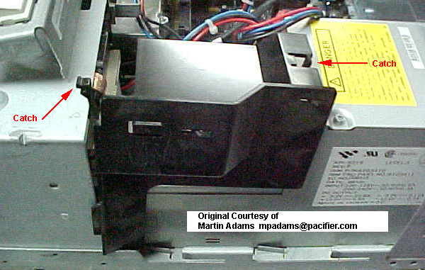
77 Multimedia Module
(Image and info from William R. Walsh)
|
|
M Microphone Jack
H Stereo Headphones Jack
HD Hard-drive Activity LED
VOL Volume Control
PWR Power Good LED
SW Power On/Off Switch
Both standard and MM control panels have a
speaker. Only the MM control panel has Microphone and
Headphone jacks (1/4" stereo jacks). The MM speaker
(behind the grille) is rated 1.5 W / 8 Ω as
compared to 0.5 W at 4 or 8 Ω. The shape is an
oval cone set into a square frame.
|
92F0002 Control Assembly - Without Volume Control (Power Switch, Cable, Speaker)
41G3929 Control Assembly - With Volume Control (Power Switch, Cable, and Speaker)
Multimedia Module PCB
(outline and info by William R. Walsh)
I would assume that the connection to the sound card
powers the onboard amplifier. With the sound card cable
unplugged the volume control ceases to function and the
speaker plays all beeps as a normal front panel would.
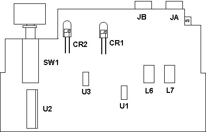
MultiMedia Module PCB, Top FRU 41G3929
MultiMedia Module PCB, Bottom FRU 41G3929
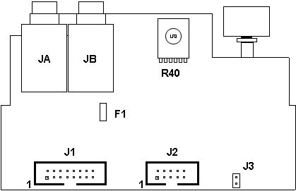
F1 Fuse for Headphone Output?
JA Microphone Jack
JB Headphone Jack
J1 Ultimedia Audio Port
|
J2 Front Panel Connector
J3 Module Speaker Header
R40 Volume Potentiometer
|
92F0113 Cable (Control Assembly to Audio Card)
96F7762 Cable (Control Assembly to System Board)
Ultimedia Port
Pinout of the pinheader found on Ultimedia-compatible cards (pinout of the
header on the panel itself should be the same).

Odd # pins top, Even # pins bottom.
| Pin |
Signal |
Pin |
Signal |
| 1 |
Out R |
10 |
Out L |
| 2 |
Gnd |
14 |
Key |
| 4 |
Mic R |
13 |
Mic L
|
Pinout courtesy of Christian Hansen.
DIY IBM Ultimedia-to-CT 5330 by pleonard
(original post on VOGONS)
Those of us (un)lucky enough to have collected an Ultimedia
PS/2 know that the audio features of this machine are a mix of good and bad:
great front-panel amplified speaker with volume control and headphone/mic
jacks, coupled to a terminally-unsupported audio card
(M-ACPA or
AudioVation, choose your MWAVE DSP
poison). The question is: how to connect that great front-panel speaker up to
a useful sound card?
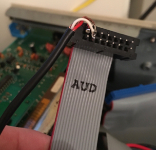
As you might expect, audio is connected through a proprietary 16-pin
connector that plugs into IBM's own audio cards. A few 3rd-party boards
(ChipChat among them) include this "Ultimedia Header", but Creative's own
Sound Blaster (Pro) MCV does not.
But since we have the pinout,
and since you can buy 2x8 dual row headers, it should be relatively easy to
solder up a R/L/Gnd cable from the line out jack on the back of the SoundBlaster
Pro:
(believe it or not, those pins aren't shorted :>)
Ed. pleonard connected Pins 1 (R), 2 (Gnd),
and 10 (L). But the wiring doesn't quite match the pinout! Yet it supposedly
worked for him... hmm. Needs verification.
As you'd expect, best results are obtained by disabling the built-in amp on
the SBPro. The result is very clean sound - contemporary (1991) reviews of the
Ultimedia mention how these machines' own sound hardware obviated the need
for external speakers for most users. Best of all, you can completely uninstall
the original DSP sound card. (Your sympathies for the original IBM sound card
will dramatically decrease when you discover how many dozens of KB of
RAM it requires to produce sound of any kind in DOS...!)
77 Case, rear (57SX shown)
Remove Case
- Have front facing away
- Unscrew both thumbscrews
- "Slap" the top of the case forward using your palms along the sides of the case.
- When the top of the case moves forward an inch and a half, pull up.
77 5.25" Drive Bay Guides
Post Notches on the reverse that fit into
the drive bay walls.
Latch Locks the guide onto the drive bay
wall.
To remove Guides
Press in the latch on the guide (rear of the drive bay) and
push the guide forward.
Guide FRUs
These are mirror images of each other, one
for the left side, the other for the right side. If you
make your own guide rails, you can cut the back end of
the rail square, so it wouldn't matter if you used the
same FRU on both sides The cutout for the gude's latches
will allow you to switch the guides to the other side
and they will work.
96F7371 (Black) Left Guide
96F7372 (Ivory) Right Guide
Original 77 5.25" Drive Rail
This was "fun". On this rail, the screw
hole marked "R" was the fixed hole, and it serves as the
reference point for the important surfaces. Note that
the center-to-center distance is 3.115". Measured that
from a drive. One hole is usually slotted so there can
be some variation between mounting screw locations on
drives.
Also, with any measurement, a few
thousandths here and there doesn't matter.
5.25" 77 Drive Rail Hack
Get the ubiquitous 5.25" AT Drive Rail. Cut
to fit. Note the web sticking down at the end of the
guide (.469"). This web has two functions - first,
limiting the 5.25" device to the proper depth. Second,
it prevents upside-down installation of a drive if you
use the original drive rails with the matching
extensions that fit the .469" rear.
I used a paper cutter to whack the rails
off to length. Use what makes you feel good - hacksaw,
sabresaw, vertical mill, ESP... You can cut the rear end
off flush- that "horn" is (as noted) to keep the drive
"upright".
Fixed Disk Bay 4C Drive Slide
96F7775, 71G5706, 71G5708, 79F3300
Seems this is a little long for OAL for it to fit into
the Model 90's lower drive bay.
9577 Air Baffle for Fixed Disk Bay 4C FRU 92F0251
The older 8557 and 9557 used a grey colored
baffle, same FRU.
This was used in older systems with hot
running drives in 4C. Modern 1" high drives should run
cool enough without it, but if you want to run a
7,200RPM (or higher) drive in your 77, you MIGHT want to
help cool it as much as possible.
Pasteboard hack
I built a baffle for a 9577 that went from
the top air grill on the power supply over to the D:
drive bay above the control module. Worked fine. A
little duct tape, some pasteboard, and shazzam! I don't
have a 77 anymore to give you dimensions.
|