|
@E9FE.ADF IBM Expansion Unit Model 001
@E9FF.ADF IBM Expansion Unit Model 002
@8EF8.ADF Expansion Unit SCSI Controller
C8EF8.ADF Init file for Expansion Unit SCSI Controller
3550210a.exe Option Disk (v1.0): Docking Station 3550
192-258 IBM 3550 Expansion Unit Model 001
192-257 IBM 3550 Expansion Unit Model 002
Power Supply
Errors
The -001 version is for the 8551 (N51) and the -002 version is for the 9552 (TP700/720).
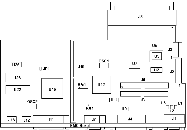
3550 Planar
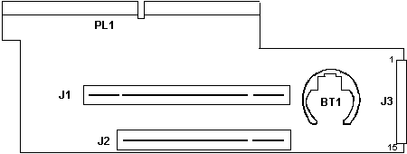
3550 Riser
J3 Pinout
Install Adapters
Open Card Retainer Catch
HD Trays
3550 Planar FRU P/N 49G2667 (-002 model)

J1 Video pass-through
J2 P1 Power connector
J3 P2 Power connector
J4 External SCSI Connector
J5,6 Internal SCSI Connector
J8 120-Pin Connector
J9 Serial Connector
J10 System Board-Sub Connector
J11 Parallel Connector
J12 Pointing Device Connector
J13 Keyboard Connector
JP1 Password clear?
OSC1 40.0000 MHz osc
|
OSC2 24.0000 MHz osc
L1-3
RA1-6 Termpacks
U2,25 Hitachi HM6264ALFP-10T
U3 49G2704
U5 AN78N05 VR
U7 Signetics P80C32GBAA MCU
U9,11 89F7000
U12 39G8766
U16 48G8903
U22 53G8411 ODD SCSI BIOS
U23 53G8410 EVEN SCSI BIOS
|
Odd configuration. The system board component side faces DOWN. The circuitboard
on top is covered with a insulating shield.
Note: The built-in SCSI controller
(-002 only?) includes an active terminator. This terminator automatically
works when an external SCSI device is attached.
3550 Riser

PL1 System Board-Main Interface
J3 LED and Power connectors
BT1 Backup Battery CR-2032
|
J1 16-bit AVE slot
J2 16-bit slot
|
The edgecard goes upward into J10 on the System board. J3 points to the
front of the case.
J3 Pinout
1 Brown +Modem
2 Red +FDD
3 Orange -FDD
4 Yellow -PCMCIA
5 Green +Charge
6 Blue -Speaker
7 Purple -Modem
8 Grey +HD
9 White -HD, -Charge
10 Black To keylock switch
11 Red To keylock switch
12 Red To Power Switch
13 Black To Power Switch
14 N/C
15 N/C
Not totally sure- the LED PCB has some bussed pins.
Installing
Adapters
You can install two full length 16 or 32 bit cards in the 3550
(but only permit 16-bit operation). Another gotcha- The slot cover guides
are the same as on other microchannel systems. But the catch for the card
guide is a sliding catch, not a flexible one like on the 76/77 models.
To open the catch
Look at the vertical card guide restraint. About 2/3rds down,
there is a horizontal tab. Push in on the end of the tab, then push the
card guide restraint forward until it reaches the stop. To fasten it back,
just slide it to the rear until the locking tab snaps into place.
Drive Tray
for HDs
When installing a 3.5" drive in a 3550 Expansion Unit, use the
hard disk drive slide assembly (FRU 85F0035) supplied with the option.
(Ed. a model 95 sled). The 3550 uses
snap-in rail guides like those in the 77 series.
|