|
5494 Front
Operator Panel
Controller Board
LCD
Keypad
Normal Power-On Display Sequence
Model Conversions
Cables
Power Supply
Power Distribution
Telesincro Power Supply With Date Code Week 01-30 1995 (H132010)
Floppy Drive
Chassis Differences
5494 Front
Operator Panel
The operator panel consists of a keypad, an LCD, and four
LEDs (Ready, Call 5494 Service, See PD Guide, and Test Mode) that indicate
operating status. An 8051 controls the LCD, LEDs, and the keypad.
Communications between planar and operator panel are through a serial port.
Controller Board
P1 LEDs
P2 LCD Panel
P3 Header to planar
|
P4 Tape connector to keypad
U4 intel 02F9476
Y1 8.000 MHz xtal
|
LCD
The LCD has 16 character positions. It is blank and displays a cursor in the
rightmost position when not in use. When the 5494 operator panel is in use,
there will always be a message code (002-01 in the above example) displayed on
the left-hand side of the LCD. The message codes are described in "Message
Codes" in topic 3.1. When the 5494 is in use, the LCD can also contain, in the
data field on the right-hand side of the LCD, a system reference code (SRC) or
information as defined by the message code. In the example, the data field
contains an SRC.
If an error occurs before or during normal operation, both a message code
and an SRC will be displayed on the LCD and an LED will be lit. If more than
one error occurs during normal operation, the message codes and SRCs will cycle
at 3-second intervals. If the error clears (a link is established after a
failure, for example), the message code and SRC will be removed from the LCD by
the 5494.
Keypad
The keys on the keypad allow commands to be entered and sent to the
5494, and include:
REQ Initiates a request function
PF1 Used for special requests
PF2 Used for special requests
Esc Used to cancel a request
Alt Enables the alternate hexadecimal
values of keys 4 through 9, to be used with keys PF1, PF2, and Esc for
additional special functions. (Ed.
Might be the SHFT key)
Enter Signals to the 5494 the end
of an input string
Clear Clears a value being
entered and allows you to begin again
0 to 9 Numerics 0 to 9
Alt+4 Hexadecimal A
Alt+5 Hexadecimal B
Alt+6 Hexadecimal C
Alt+7 Hexadecimal D
Alt+8 Hexadecimal E
Alt+9 Hexadecimal F
Up arrow Scroll up through several
choices or panels of data
Down arrow Scroll down through
several choices or panels of data
Left arrow Move the cursor left
or scroll to additional fields of data
Right arrow Move the cursor right
or scroll to additional fields of data.
If you hose the refstamp, the 5494 will not boot up and
the error code '003-04 1' is displayed on the Op Panel.
Normal Power-On Display Sequence
Soon after the 5494 power pushbutton is set to ON (|):
- All LEDs are ON for 1 second.
- All LEDs are OFF for 1 second.
- The Test Mode LED is switched ON.
- 001-01 is displayed, indicating that POST is running.
- The date and time are displayed on the LCD.
- The microcode is loaded.
- The Test Mode LED is switched OFF.
- Within 10 seconds, the Ready LED is switched ON
Model Conversions
Model 001 or Model 002 to Model EXT. Model 001 and Model 002 can be
made functionally equivalent to Model EXT by installing level 3.0 microcode
or later.
Cables For 5494
72X5645 - Cable Asm, Twinaxial Workstation Adapter (Ports 0-3)
03F0386 - Cable Asm, Twinaxial Workstation Adapter (Ports 4-7)
The Twinaxial Workstation Attachment cable connected to the lowest number
slot supports twinaxial ports 0-3. The Twinaxial Expansion Adapter, if
installed, supports twinaxial ports 4-7.
If the Twinaxial Expansion Kit is installed, the communication interface is
located on the twinaxial adapter in the lowest slot number.
Power Supply P/N 03F0420 / KRON (?) 55JET064
Global Manufacturers' Services Valencia, Spain
Uses a Model 90 form factor PSU, but wimpier. No HD power plugs.
Input: 100 - 240 V, 1.6 - 0.78 A, 50 / 60 Hz
Output: 63.8 W
+5 V 10 A
+12 V 0.80 A
-12 V 0.35 A
Uses an NMB Boxer fan, 3610NL-04W-B10 12 V, 0.13 A, ball bearings, brushless.
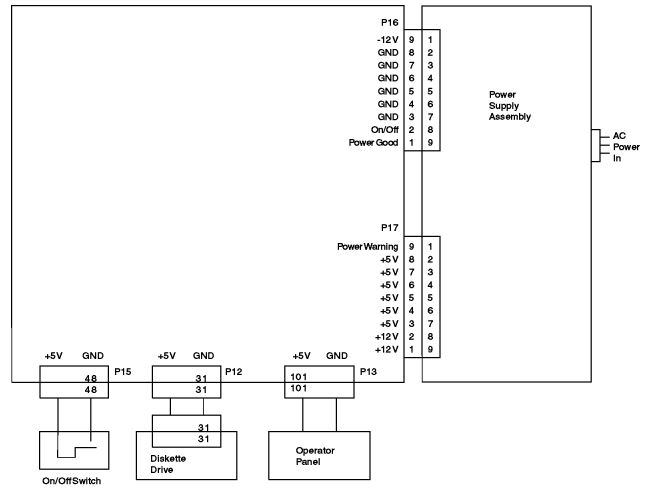
Power Distribution
Telesincro Power Supply With Date Code Week 01-30 1995 (H132010)
If 5494 experiences power related problems, verify power supply is not
Telesincro dated week 01 through 30 1995. If p/s is within this date code,
replace power supply.
Floppy Drive 52G3400, P/N 10H4267
![[P]](/other/img/photo.gif)
Note: 64F0204 / 64F3197 BUT it has the Mitsubishi
MF356F-822MB "*" floppy.
In IBM's eyes, there's no need for more than a one device cable... Bay B has
the LCD display, Bay D has the "glove box" Bay C is inaccessible.
Why waste good money on even a twist? There can only be one... floppy
[Highlander]. Why use a three-device cable like the Model 90 if you will only
be able to use one device... ever.
Note that the 5494 does have the Adapter Card-Guide Assembly 33F8363. It
does not have the 92mm Base Fan.
Chassis Differences
There are (at least) two different chassis styles.
Many 5494s use the original PS/2 Model 90 chassis. These
units can be identified by the presence of the hard-drive activity indicator
on the front bezel (the opening is present, but the light pipe is replaced by
an opaque plug and the LED is missing). The top cover is made of plastic (one
piece with the front bezel) and has a metal EMI shield on the inside. The cast
metal backplate comes straight from the Model 90, and since the 5494 doesn't
have any external planar connectors, the I/O opening is covered by a piece of
plastic. Even the complex/adapter/fan support is reused, but the fan itself is
missing.
Known samples: plant code 77 - Spain, mfg. date: 1997
Some other units use a retooled chassis that may look similar, but is quite
different construction-wise. The top cover is made of sheet metal, front bezel
is a separate piece and completely lacks the HD activity indicator. The
backplate was also redesigned - there's no planar opening and no keylock hole.
The adapter card support is made of metal, lacks the fan mount, and is riveted
to the case base.
Known samples: plant code 82 - Brazil, mfg. date: ~1994
|