|
The IBM "Setup Aid" tool for an 8228 Token-Ring 'MAU'! (video by David Beem)
8228 Setup Aid
Using the Tool
Inside the Setup Aid
DIY Setup Aid
Test Dongle for DE9 Port
8228 Setup Aid FRU P/N 6091004 (69X8369)
The relays in the 8228 are very sensitive. Most 8228s fail to operate
properly when they have been relocated and/or dropped.
This "8228 setup/testing tool" *must* be used on any of the 8 data-station
ports once before using the MAU, to "prime" test the relays and re-align them
after transportation. I got all my MAU from customers that claim these were
defective and all of them did fine after treatment with the "setup/testing
tool".
Using the Aid
Note: Use the IBM 8228 Setup Aid after you have
installed the 8228 and before you connect any cables to it.
Warning! The aid should never be used when the
network is operating!
Before you begin make sure no cables are connected to the 8228. If a
cable bracket has been installed on the 8228, remove it. Insert the aid into receptacle 1 of the 8228. The yellow stripe
should be aligned with the edge of the receptacle to ensure that the aid is
firmly seated. The light will glow brightly when the aid is initially inserted
and will gradually dim when the aid is firmly seated in the receptacle.
If the light does not glow brightly when you insert the Setup Aid, remove
the screw from the aid and replace the battery. If the light still does not
glow brightly after you have replaced the battery, try another Setup
Aid. Leave the aid in the receptacle for four seconds after the light has
gone out (Ed. Wait to hear the "click" when the
relay is energized). Remove the aid from the receptacle and insert it into the
next receptacle. The yellow stripe should be aligned with the edge of the
receptacle to ensure that the aid is firmly seated. Go to the next receptacle
and repeat this step until you have set each receptacle, 1 through
8. When you have set receptacle 8, insert the aid into the RI
receptacle for four seconds. The light should glow brightly while the aid
is in the receptacle. If the light does not come on or goes out while the aid
is connected to the receptacle, then the 8228 must be replaced.
Inside the Setup Aid
At least two different versions were produced:
Notice the different battery orientation and retention method.
DIY Setup Aid
(from Peter's site, edited - original HERE)
One thing if you build your own - there are two "short-circuit" bridges at
the front of the "normal" IBM plug, which connects the two pairs of wires when
the plug is pulled out (automatic internal loopback). These two bridges must be
removed on the "Setup Aid" - or else the LED will light up continuously.
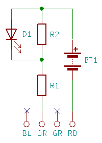
Here's the wiring for the IBM 8228 Multistation Access Unit (MAU) Setup Aid
This Aid is -usually- a small, handy tool, which is required to setup
and test the IBM Token-Ring MAU 8228.
You will need:
- a soldering iron (a good one - as usual)
- a multimeter with Ohms-range or continuity checker
- an IBM ICS Token Ring plug (maybe cut from an old cable)
- parts as specified below
- some self-confidence (Yes - like always)
Wiring And Parts

|
D1 - 3mm red LED
R1 - 1 KΩ, 1%
R2 - 561 Ω, 1%
BT1 - 9V Battery (clip)
|
Front View of the Connector
+--------------------+
| +-------++-------+ |
+-+       ++       +-+
| |                | |
| +-##--##--##--##-+ |
+-+-------++-------+-+
||  BL  OR  GR  RD  ||
|+------------------+|
+--------------------+
|
|
BL - Black
OR - Orange
GR - Green
RD - Red
|
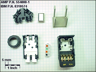
Disassembled IBM Cabling System (ICS) Plug

From upper left to lower right:
Cable Retainer - Shield Holder - Plug Retainer
Retainer Screw - Upper Half - Wire Holder - Lower Half
The lower half contains self-cutting wire contacts.
The wire holder has the IBM wire color code atop.
Test Dongle for DE9 Port
> I wondered aloud to Tony about a small dongle pass-through on my P70 TR
card to 'ring-in' to a mini-MAU if not attached to anything else. Something in
a media filter sized package?
Peter has a flashback and says:
Solder two 470 Ohms resistors diagonally across a Sub-D 9 male
plug. 1 - 6 and 5 - 9. That's exactly the layout of the "testing dongle" used
for the TR diags. You could even fake out a server with that, which otherwise
would come up with a "lobe error" when not connected to a MAU.
|