|
8229 Bridge Manual First Edition (March 1994)
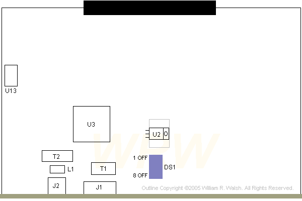
Ethernet Card Outline
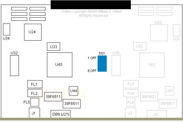
Single Interface TR Card Outline
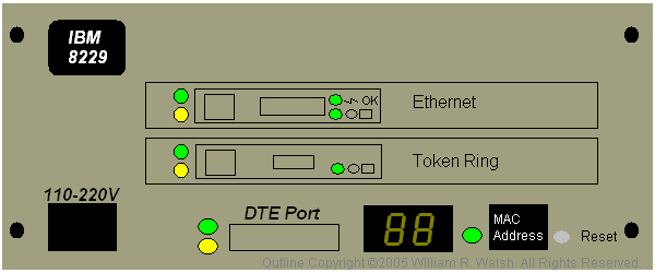
Front Panel & Thoughts (to get you started)
This is what you need to have when the MADness progresses far enough
that you have a while pile of Token Ring cards, one or more MAUs of
some kind and a desire to have your TR network talk to a pre-existing
Ethernet network. There is also an earlier 8209 LAN bridge product that
I've never seen. 8229's seem to have become pretty scarce in these
modern times.
Caution: The 8229 LAN bridge was sold with a wide
variety of configurations with many different interface cards
available. Make sure you know what you are buying if you want to get an
8229.
Based on content by William R. Walsh (original HERE).
10 Megabit Ethernet Card P/N 73G4764, EC C98333

DS1 8 position DIP switch
J1 15-pin AUI
J2 RJ45 connector
J3 120-pin connector
L1 PE-65428
|
T1 Vitec 24Z4106
T2 Valor FL1066
U2 NS LM2940CT (w/ PCB heatsink)
U3 AMD AM79C990KC
U13 20MHz crystal
|
J3 (not labeled) is the large black
connector shown at the top above. It is a Burndy RPI120U30RB-1 3-row, 120-pin
connector.
Single Interface TR Board P/N 73G4762, EC C98603

Components in grey above would be populated on the dual interface TR board.
There are nothing but solder pads for any of these items. I would assume the
components between the two "halves" of the board are identical.
39F6511 PE-65101
DS1 8 position DIP switch
FL1 PE-65185
FL2 PE-65186
FL5 PE-65184
J1 RJ45 UTP TR connector
J2 (?) DE9 STP TR connector
|
P2 (not labeled) 120-pin connector
U24 63G9811 MCA BM
U32 27-8133-01 Rev G
U33 32.000 MHz
U33 4.00 MHz
U40 50G8180(ESD) TR proto
|
P2 (not labeled) is the large black
connector shown at the top above. It is a Burndy RPI120U30RB-1 3-row, 120-pin connector.
U24 63G9811 MCA bus master interface
chip "Maunakea".
U40 50G8180(ESD) Token Ring protocol
chip "Huntingdale".
Front Panel / Powerup / Thoughts

Sooner or later I'll get all the features of the 8229 in my "outline"
above...
The reset button above is used to blow away all the settings in the 8229's
NVRAM. DO NOT PRESS IT unless you REALLY want to do
this. That said, pressing the reset button should be done on an 8229 that you
have just acquired--just to be sure that any garbage resident in memory is not
present. Press the button with power applied...if you get it, the unit will
reset and start running through its POST (numbers on display). My 8229's reset
button didn't click or give any other obvious indication that it had been
pushed. Use a fine pointed object like a paper clip, ball point pen or anything
else that isn't likely to break off in the button hole.
If you want to do a soft reset, do not push the RESET button! Simply
pull the power cord, wait a bit and plug it back in.
Chances are pretty good that if all you want to do is connect your Ethernet
and TR networks together that all you need to do is plug in the cables and
power up. I'd suggest reading the manual to confirm the DIP switches on both
interface cards are set correctly. Actually, reading the manual is a really
good idea, so go and do that now. See the top of this page to find the
manual.
The little LCD (dual 8s in the picture above) is used to display the unit's
POST, which takes about 90 seconds. During that time you will see numbers go by
on the display. When all is said and done the display will be blank in normal
operations. You should not see any yellow lights once everything has started
up. The DTE port can be used to connect a PC running a terminal emulator. You
can use this to access the built in operating programs of the 8229 or to
redownload the operating software. Redownloading the operating software may be
needed if you change interface cards.
Yellow lights indicate a fault condition has occurred somewhere on the 8229.
Check your cabling if any yellow lights should come on. There are four
MAC addresses indicated on the 8229 (if the sticker hasn't been lost or
damaged). The topmost MAC address is assigned by the unit's software to PORT
1. PORT 2 will take the second indicated MAC address (immediately
below the first). The remaining two MAC addresses are reserved for
"future use", which probably means they are and never will be used.
Hint: If your 8229 seems to get stuck around the 60s in its self test, power
down (pull the plug) and check your network cables. I found that one of my
category 5/RJ45 cables wasn't wired on all pins. This kept the TR card in the
8229 from "ringing in" and starting up.
If you want to do so, getting inside is easy enough. Remove the four screws
(black dots) above and slide the back casing away from the unit. You'll be left
with a chassis containing interface boards, power supply, front panel and the
planar board.
The insides are somewhat interesting. On the planar board sits an IBM
486SLC2 CPU (thanks David!)...seems like a lot of computing power for such a
simple device. I don't know what this CPU is actually used for. The power
supply the same as that from a Model 35, 56 or 76. There is no power switch on
it. Mine is an IBM P/N 06H3667 unit made by Delta. It looks to be of the
autoranging type...
You can use the 8229 on either a table top or in a rack mount enclosure.
Whatever you do I would suggest plenty of air circulation. I find the built in
PSU fan to be a bit weak-kneed...my 8229 grows pretty warm in operation on a
desk top. I don't feel a lot of air moving through it and the fan seems to be
working fine.
|