|
Planar
VRAM Installation
OS Thoughts
Make A Power Connector
Based on content by William R. Walsh (original HERE). Edited by Major Tom.
What Is The 7386?
The 7386 is a planar upgrade for Model 25 PS/2 computers, marketed by IBM to
the educational market.
I know of one other upgrade for the Model 25. Made by Reply Technologies,
the Model 25 Reply Board offers true 486 performance for the IBM PS/2 Model 25
computers. Whenever you hear about upgrading the Model 25, the Reply board will
undoubtedly come up at some point.
To say that the 7386 is not common is an understatement. I have the only
ones I have ever seen or heard of. As rare as it is, the 7386 is a pretty
decent upgrade for the Model 25, which came in three types: an 8086, a 286, and
a 386sx. The 7386 adds to that a 386slc, and possibly also a 486 processor
equipped system.
The 7386 is not a standalone Model 25 - it is a unit that was
upgraded from any of the other two models, 25 or 25-286, but not the 25SX,
which has a totally different system base layout.
I have four of these... got 'em from my local high school.
The 7386 upgrade does not go into the 25SX! The 25SX's layout is very
different from a 7386 planar's layout!
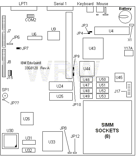
Planar

J7 IDE Hard Disk
J8 PS/2 Floppy
J15 Hard Disk Power Connector
J17 Monitor Connector
JP? External speaker?
JP3 ?
JP4 ?
JP6 ?
JP7 ?
JP8 Memory bank selection?
JP9 ?
JP10 ?
U4 Intel i8042
U6 24.0000 MHz osc (for an FDC)
U9 Acer M5105 A3E
|
U24 IBM Video BIOS
U25 BIOS (Phoenix A386S)
U26 IBM 386SLC-20 CPU
U30 Math coprocessor socket
U31 14.3181 MHz osc (RTC and ISA bus)
U32 40.0000 MHz osc (CPU)
U33 OPTI 82C283
U43 OPTI P82C206
U44 Tseng ET4000AX
U45 Music TR9C1710 RAMDAC
U46,47,50,51 VRAM upgrade sockets
U48,49,52,53 512K VRAM (4x256K 70 ns)
X1 32 MHz osc for CMOS Clock
Y17A 14.31818 MHz osc
|
Keyboard and mouse connectors are reversed from the way they are normally
installed on a PS/2.
VRAM: 256K 70 ns DIP - 4x soldered, 4x socket for upgrade
This board's got more jumpers than the earth has people - almost. Apart from
JP3, which removes the power on password (in case you forget it) none of the
others are documented, and I have no idea what they are for.
Installing VRAM
Easy as drop it in and go. Chips must be 70 ns or faster--slower ones do not
work and cause lock-ups. Make sure the chip orientation is correct, or you
could damage the VRAM chips, planar, or both.
Results: You won't see a speed improvement. You will, however, get the
ability to run higher resolutions.
Warning! Though the 7386's SVGA chipset can do
800x600 (and beyond, up to 1280x1024) you will do serious damage to the
monitor in your Model 25 if you try to run any mode outside of 640x480 at 60Hz
(V) and 31.5kHz (H)!!! The only reason I know what the 7386 board is capable of
is because I put one in a Model 30-286 and I used an external, multisync
monitor to find out!
Color depth is another story: Upgrading the RAM theoretically gives you the
ability to run a higher color depth at 640x480 and beyond (see note above). I
tried running 640x480 at 64K color depth, and it wouldn't work under Windows
3.11. All I got was an error, stating that "The video driver could not
provide the mode requested." and then I was dumped back out to a DOS
prompt.
I do not know at this time what is placing the limitation on the video--the
RAMDAC runs up to 1280x1024 (with 16 colors), and the video BIOS has support
for that mode, so why wouldn't it have support for high color modes, just as it
(seemingly) does for high resolution? The Windows 95 drivers don't help solve
this problem either. From the looks of things, the ET4000AX chipset does not
support high color modes. Only Tseng ETxxxxW32 chipsets support those modes. A
transplant of a BIOS from a W32i based card got my 7386 doing high color, but
it was not stable.
Thoughts on operating systems
Windows 3.1x and DOS seem to be the best bets. The system performs very well
with either, as would be expected.
OS/2 would probably work acceptably well, but I've haven't tried it and
don't know.
Linux: No. I tried to install Linux and it just kept locking up during the
install process.
Win95: As a thought, I took out the last remaining 7386 that I hadn't done
anything to yet. Wired up an IDE hard disk (650MB), installed a
"Diskmangler", and ran Win95 setup. Works just fine, but a little
slowly. A CPU upgrade would make a big difference, I am sure.
Win98: Yes, but it is even slower than WinNT on this thing.
WinNT: Workstation 4.0 is the only version I've tried. It ran, but did it
ever beat the devil out of the hard disk with swapping. Plus, it was
S-L-O-W!
Make A Power Connector
The 7386 planar upgrade has support for both the hard disk that came
installed in the Model 25 and 25-286, and a standard IDE hard disk.
However, the 7386 has an odd miniature power connector. An adapter can be
made, as shown here.
What you need:
- (1) 3.5" Device Power Connector (the small ones)
- (1) 5.25" 4 Pin Molex Device Power Connector
Both should have wires attached already. I would recommend getting these
from a dead PSU.
- Some Electrical Tape
- Wire Stripping Tool
A soldering iron is not really needed, but if you want to solder the
wires together...
Disclaimer: I take no responsibility
for any disasters that may occur if you actually do this! If you don't feel
comfortable doing this, then don't! One “BZZT!" and you could burn something
important!
What to do:
- Strip the wires... about 1/2 inch from each wire should do it.
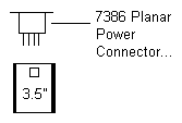
- Join the wires. This is the tricky part, as the 7386's on-board power
connector is wired with 5 and 12 V “swapped” from the way it is normally
wired. To elaborate. If you go by the wire color, and wire what would normally
be 5V to the 5V at the point of joining the two cables together, it will really
be 12V and plugging that into something would let the magic smoke escape very
quickly! See the picture.

Of course, this assumes that you put the 3.5" drive connector over the 7386
planar pins so that the small piece of plastic that comes out of the 7386
planar pins goes into the "bevel" that is cut into the 3.5" floppy connector.
If you do it the other way around, then you will not need to swap the
wires.

|