|
From David L. Beem:
I trimmed the clear plastic (darker center area
of the riser) around my solder pads & scraped the
insulator coating away with a knife. Tinned up the leads & solder pads
liberally to put them in place.
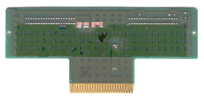
The red 5 volt conductor should be
positioned to the side of the solder pad as I have it
because a plastic rib on the drive platform will
interfere if it is centered. The finished hack looks
like this:

Ed. Maybe a shot of
hot melt glue to help keep the conductors from being
pulled around and fatiguing the solder joint?
Warnings and recommendations from Peter Wendt:
Remember, the Model 50 power-supply (94W!!!) is
known to have lesser power than assumed. If you'd already
installed a 386/486 upgrade, 64Megs of RAM, SCSI adapter
and a hi-resolution graphic board it will surely collapse.
|