|
fpkit290.zip DEC FDDIcontroller/PCI DOS-based Distribution Diskette V2.90
ffmgt110.zip DEC FDDIcontroller Network Management Tool V1.10 Full Kit
DEC FDDIcontroller/PCI Installation (EK-DEFPA-IN)
FDDI System Level Description (EK-FDSLD-SD-002)
FDDI Network Configuration Guidelines (EK-DFDDI-CG-01)
FDDI Adapters Technical Data (official website, archived)
DEC DEFPA-UB Adapter
Specifications
PHY LED (Diagnostics)
DEC DEFPA-UB Adapter 54-22499

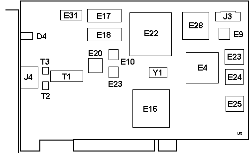
D4 PHY LED
E4 MC68HC000FN16
E9 AMD PALCE
E10 AM79865JC Physical Data Transmitter
E11 AM79866AJC Physical Data Receiver
E16 SC02PH019DH02 21-40779-02
E17,18 HY514260B JC-70
E20 DP83223V Twisted Pair Transceiver
E22 VLSI VY06780 21-34812-04
|
E23 LAN ADRS
E24, 25 N28F001
E28 MC68848PV
E31 M5M44266-BJ
J3 Unk
J4 Port A - UTP (called MJ by DEC)
T1 Pulse PE-68517
T2, 3 TDK ZJYS-2
Y1 50.0000 MHz osc
|
Specifications
The major components on the adapter are as follows:
- 1 megabyte of packet memory
- 68000 onboard processor
- DMA control
- 32-bit, 33 MHz PCI bus interface
- FDDI interface chipset
- IEEE address ROM
- Onboard, nonvolatile memory for firmware storage
DC amps @ +5.0 V, 1.1 A - SAS UTP
DC amps @ +12.0 V, 0.1 A (maximum)
Bus loading - per PCI standard, Revision 2.0
PHY LED (Diagnostics)
| Color |
Status |
Condition |
| Green |
On |
PHY connection complete |
| Green |
Blinking |
PHY connection in progress (or no cable attached) |
| Amber |
On |
If on after system boots, indicates port or Link
Confidence Test (LCT) failure; retry loop
If on before system boots, indicates self-test
failure |
| Green / Amber |
Blinking |
Alternating—(DEFPA-DA and DEFPA-MA only)
|
None
|
Off
|
Port disabled by management or LED or adapter fails |
- Turn on power to the computer and observe the PHY LED.
- Note the following events (within 10 seconds after the computer power is
turned on):
- The PHY LED flashes green (three flashes) for approximately 1 second.
- The PHY LED turns off when the adapter passes the powerup self-test.
A steady amber LED indicates a powerup self-test failure.
|