|
The Problem
Possible Solution
Implementation
Warning: The power supply unit contains dangerous
voltages, even when unplugged! Improper manipulation may lead to an injury,
death, fire, and/or other damage. The author is not responsible for your
actions and their consequences. Proceed at your own risk!
Content by Tomáš "Major Tom" Slavotínek.
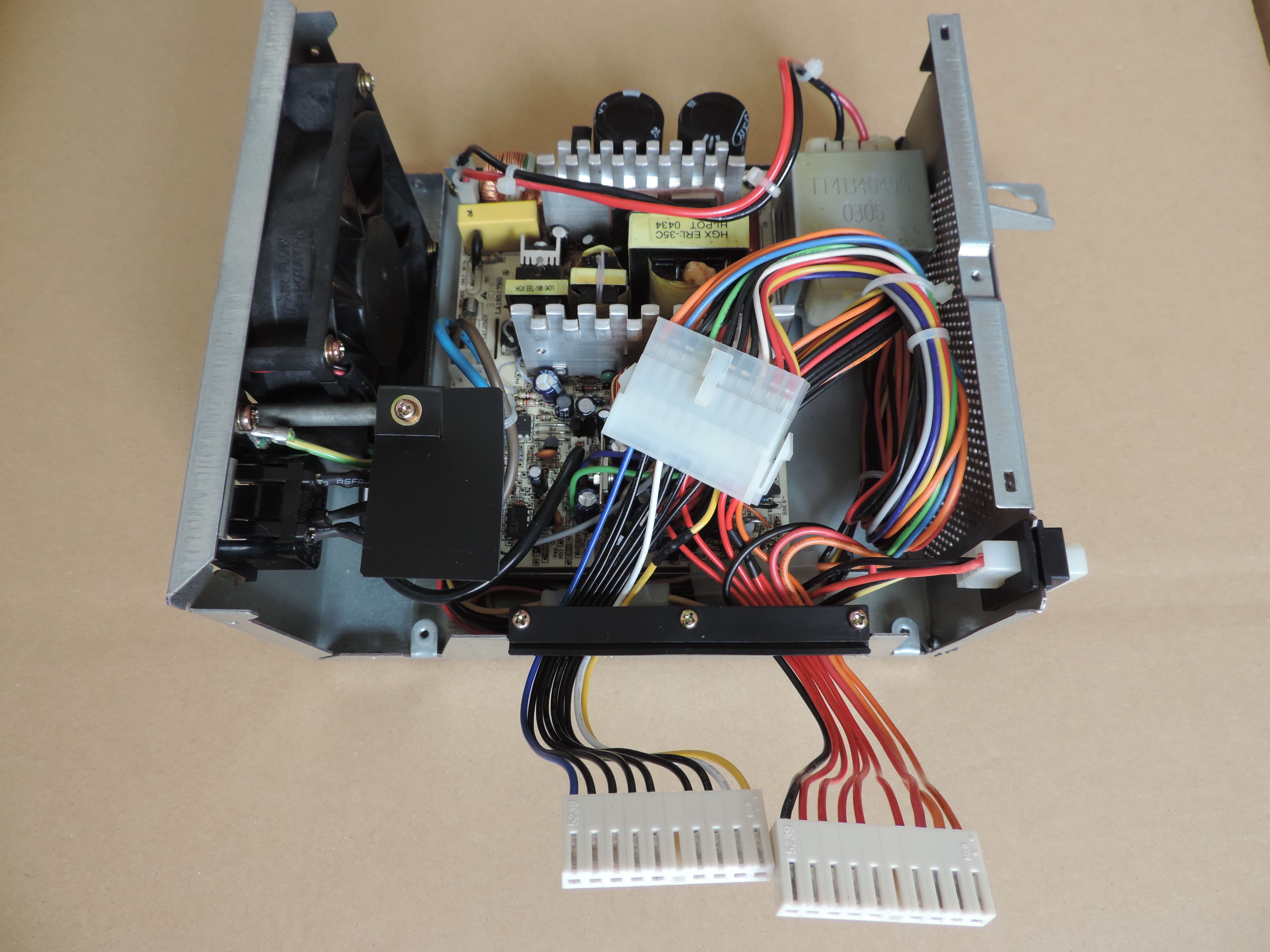
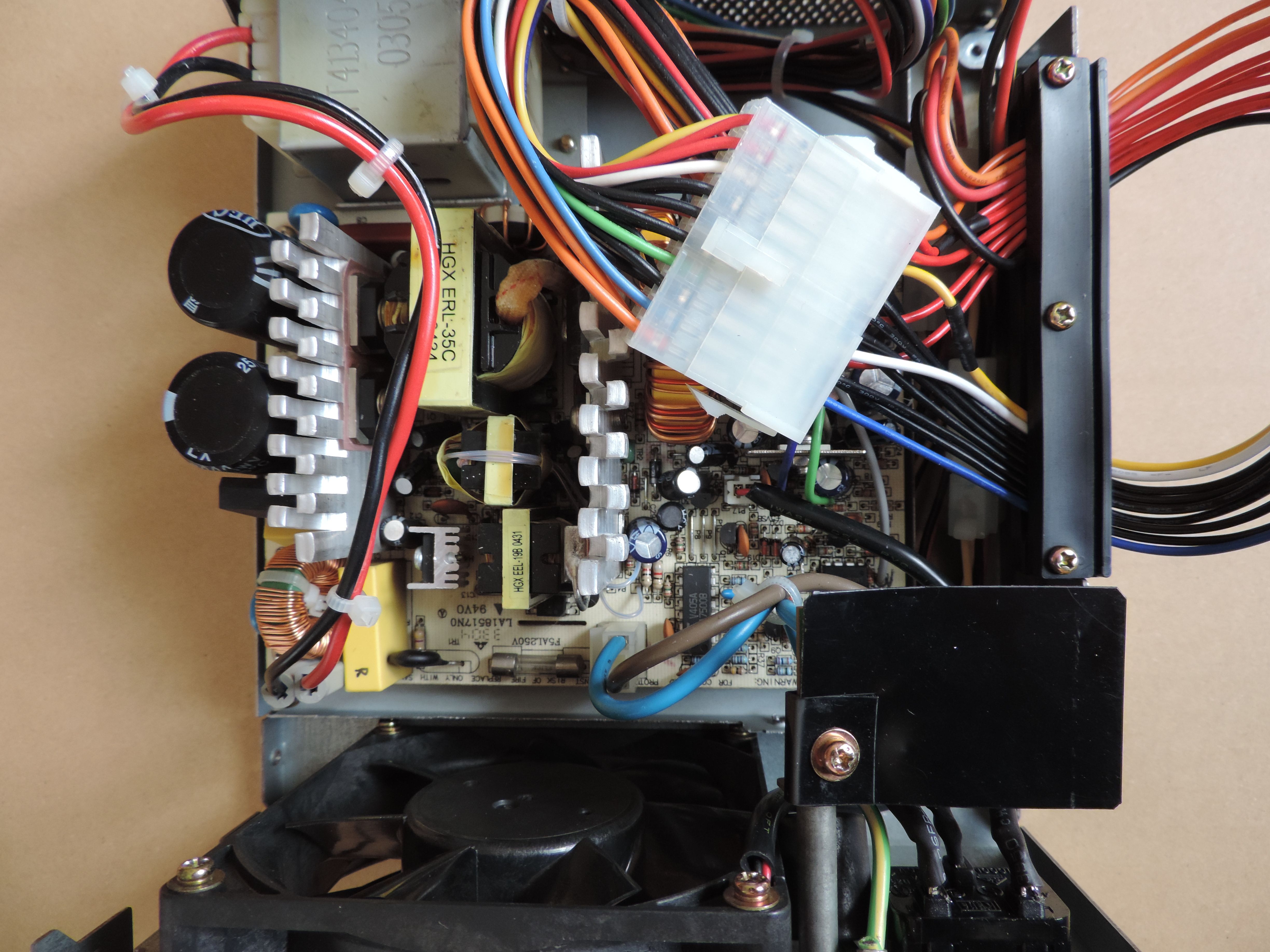
The Problem
The PSU in my 5560-W1 had a problem - it would rarely power on, and even if
it did, the output voltages were unstable, and the Power Good signal never
became active. The problem was accompanied by a "coil whine" in the standby
transformer - this was always present, even with the PSU shut down. I've
narrowed the problem down to the input stage - more specifically the part that
likely deals with the 100-125/200-240 V auto-ranging (based around 2 triacs and
1 phototriac). I've discovered a few suspicious caps and a whole bunch of
crummy solder joints. Addressing these problems made the PSU more stable (incl.
the Power Good signal), but sadly it wasn't stable every time and usually not
for long either. The input stage is controlled by an unknown circuitry on a
ceramic board. I say "unknown" because the entire thing is potted by some
compound, making further analysis and potential repair difficult and
time-consuming.
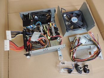
After a few more experiments, I've decided to put the original PSU guts
aside and replace them with something slightly more modern, and more
importantly - functional.
Possible Solution
It's Time to Choose...
The most obvious choice is to replace the unit with a regular ATX power
supply. But things are not that simple - we can't use just any ATX PSU - we
have to respect the original current ratings. Especially the 5 V rail can be
problematic as the original unit can supply up to 28 A @ 5 V - this is what
powers all the logic (planar, processor complex, adapters, disk logic...).
For this reason, we want to choose a supply that conforms either to the
original ATX or the ATX12V 1.x standard. Most PSUs from that era should be
capable of supplying enough power @ 5 V - the rail is typically rated at 25 -
30 A for most 300 - 350 W units. The later ATX12V 2.0 standard redefined the
power distribution, and the PSUs supply most of the power through the 12 V rail
- instead of the 3.3 V / 5 V pair. The 5 V rail on these "new" units is
typically rated at 20 A or less, which isn't ideal for our use case. (One could
brute-force it and use something like a 750 W supply with a high enough current
rating @ 5 V, but that's not great either - the PSU won't be balanced properly,
plus these "larger" units aren't exactly cheap either).
The ATX12V 1.x units are probably the best choice - they are newer than the
original ATX bricks and tend to be more robust. But you can use whatever you
have available, as long as it fits the current requirements.
Form Factor
Luckily for us, the standard ATX units are somewhat smaller compared to the
original 5560 unit:
5560: Height: 86 mm front (96 mm back), width: 178 mm, depth: 196 mm
ATX: Height: 85 mm, width: 150 mm, depth: 156 mm
This means that in most cases the ATX guts should fit to the original 5560
PSU with no problem. We should even have some extra room for the wiring and
whatnot.
Wiring
Wiring is what we need to discuss next. Since we have decided to go with the
ATX or ATX12V 1.x PSU, we are stuck with the older 20-pin ATX motherboard
connector:
The availability of the other connectors and their count may differ from one
unit to another. Generally, there should be a combination of the following
plugs: the 12 V motherboard (CPU) supply, possibly a 3.3 V / 5 V AUX connector,
and then at least a few "Molex" disk drive connectors.
When we compare the pinout of the main 20-pin connector to the
5560 PSU pinout, we can see that all
required voltages and signals are available to us on this one plug. We will
need two additional 5 V conductors and one 12 V line, but that's not an issue,
we can borrow these from one of the other connectors. Alternatively, we can
splice the original "20-pin" harness to add these lines (this is ok to do if we
don't push it too far - the connectors used on the ATX PSUs are typically rated
for 7-10 A per pin, the 5560 planar plugs for 4 - 5 A).
There are many ways of wiring the adapter cable - the picture below illustrates the
method I've decided to use:
Notes:
Pins marked with a red cross are unused.
The used colors match the original 5560 scheme rather than the "standard" ATX one.
As you can see, I've derived one 5 V and one 12 V line from an additional
"Molex" connector, and one 5 V line on the 20-pin connector was spliced - a
compromise between cabling complexity and robustness of the solution.
You may be curious about the -PS_ON (-ON/OFF) and PWR_OK (Power Good)
signals and whether they need any special treatment. The answer is no. The way
these signals work is the same for both the ATX and the 5560 PSU design - we
can wire them to the appropriate pins, and that's it, no additional circuitry
is needed.
Implementation
Now that we have a fairly good idea about what it is that we are trying to
achieve, it's time to realize it.
Planar Adapter
Let's start with the cable adapter. For this, we will need a cable crimping
tool and the appropriate terminals and
connectors.
Possibly the easiest way to approach this would be to snip the original ATX
connectors and replace them with the "new" terminals. However, this approach
has one major downside - if the ATX PSU fails or you decide to use a different
model, you will have to do all this work again. (or you could desolder all the
wires from both units and swap the harness, but that can be hard because the
wires are typically bunched together and flooded with large amounts of
solder)
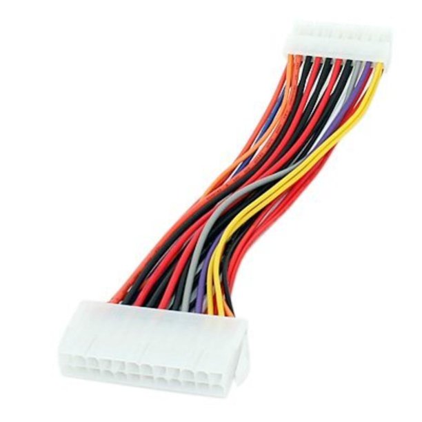
A more future-proof approach is to buy one of the
20-pin ATX extension cables or am ATX 20-
to 24-pin adapter and modify it instead. You can easily unplug this ATX to
5560 adapter later on and use it with another PSU. That's the approach I've
decided for:
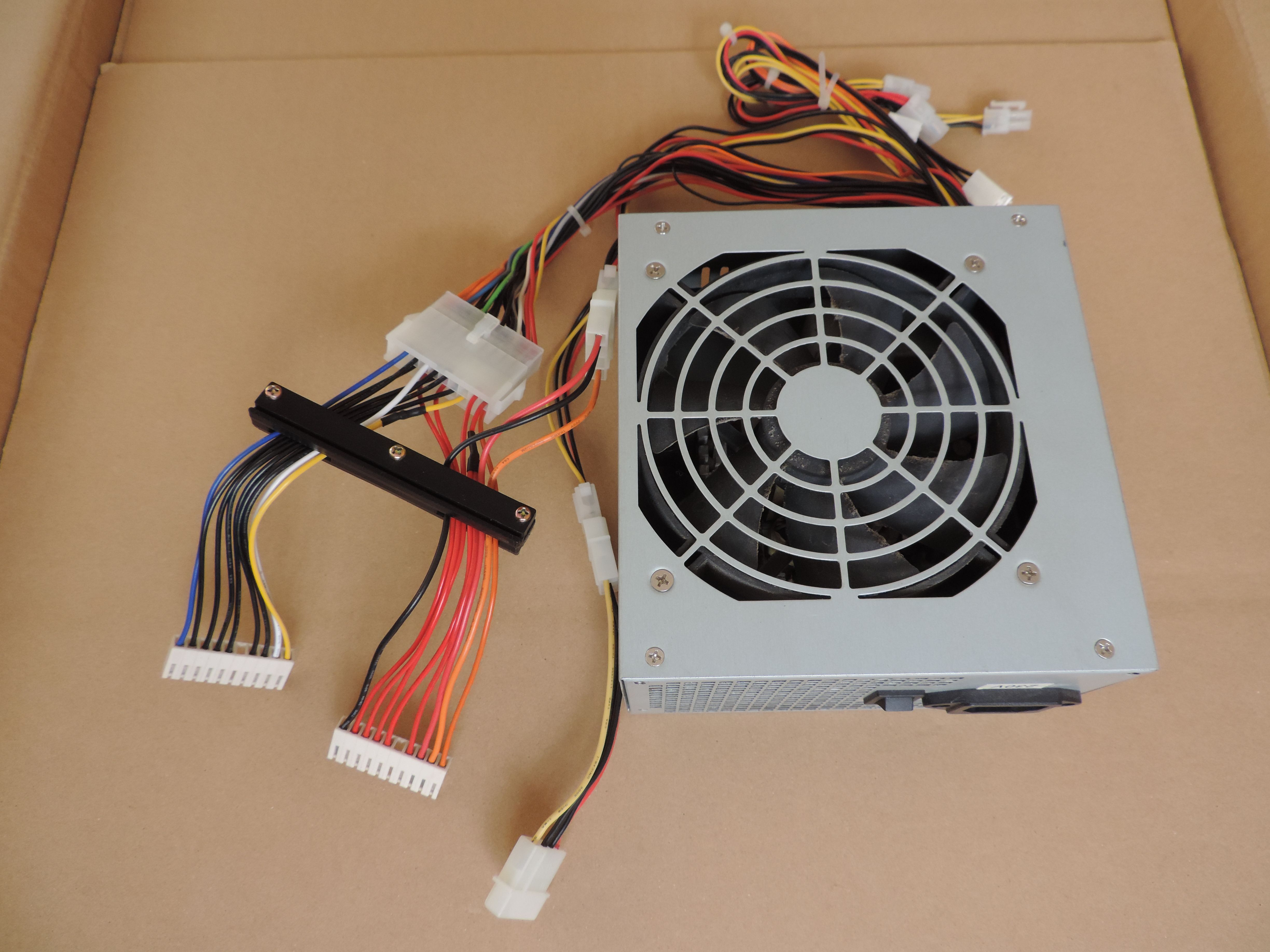
The 20- to 24-pin adapter I've used was about 15 - 16 cm (6 inches) long,
and that proved to be the perfect length (I've lost perhaps 1 cm by cutting the
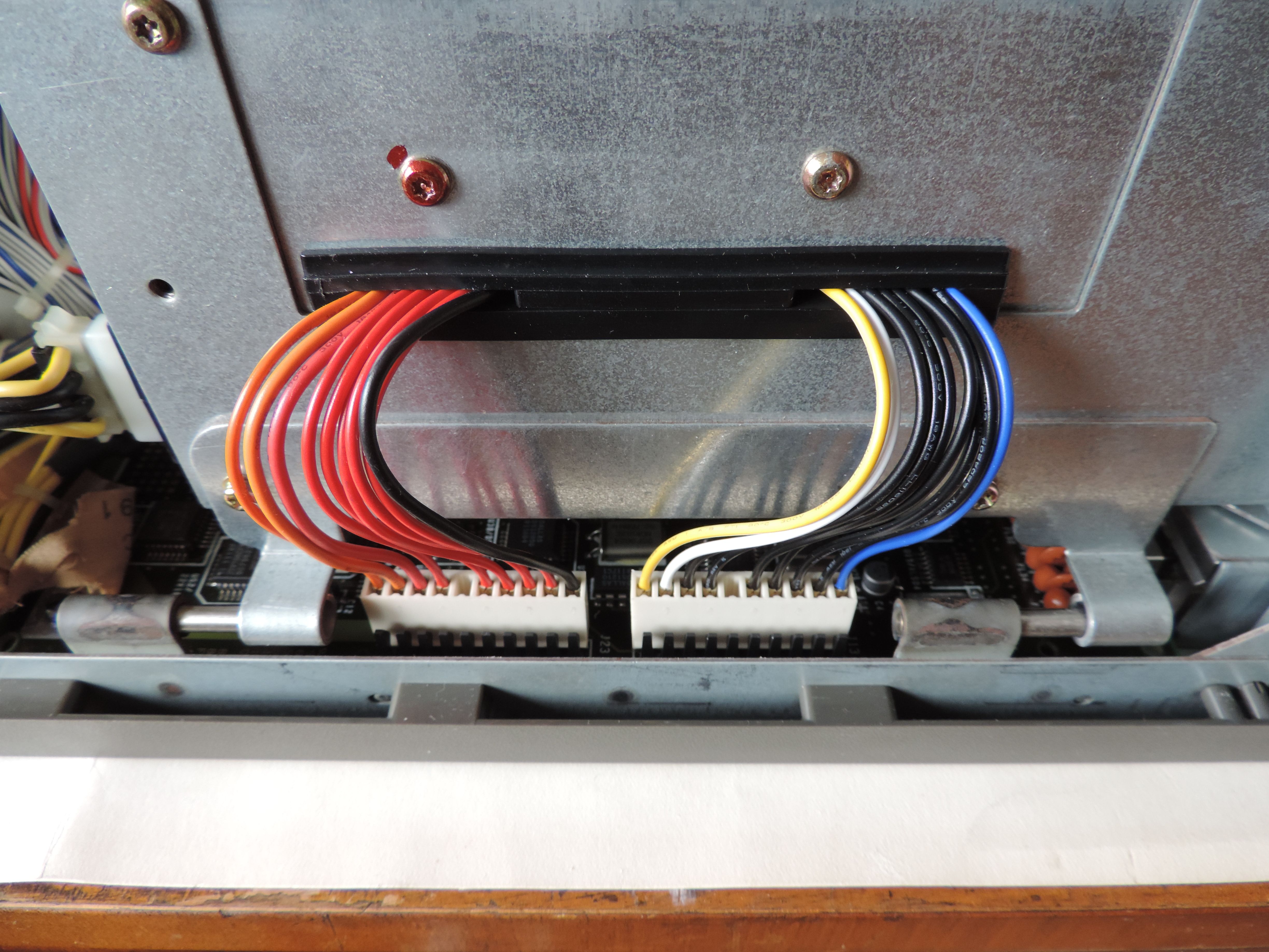
old pins and crimping the new terminals). The used wires are 16 AWG - the same
as the original ones. The black retention bracket is from the 5560 PSU and
comes quite handy even when building the adapter, as it holds all the wires in
place and in the correct order.
Three additional conductors - 5 V, 12 V, and Ground - go to a standard male
"Molex" connector. There were enough ground connections on the 20-pin ATX
connector, but it's a good practice to have a return path on every power
connector.
When you have the adapter ready, check it for any defects - especially
shorts. Then test your work by connecting it to the ATX power supply you intend
to use as a replacement, shorting the -PS_ON pin to one of the grounds, and
measuring the voltage on all the other pins (PWR_OK/Power Good should be logic
high - between 3.8 and 5 V).
If everything checks, you can connect the adapter to the 5560 planar, "flip"
the switch, and see if the systems works (you should also double check all the
voltages again).
Molex Adapter
The 5560 PSU has one male "Molex" plug for the drive power harness. Once
again, you can either crimp a male plug in place of one of the female ones -
directly on the original ATX wiring harness or build a male-to-male extension
(see the photo above).
Mounting
When we are done with the electrical part we have to figure out how to hide
the ATX guts inside the 5560 PSU shroud. The actual method will somewhat differ
from PSU to PSU and person from person.
I didn't want to modify the original PSU shroud in any way - in case I
wanted to return to the original 5560 PSU electronics later on. In any way, the
ATX PSU board is somewhat smaller than the 5560 one, so you will have to get
creative with the mounting solution. There is a metal post in the middle of the
metal base - make sure it doesn't touch any of the parts or traces (don't rely
on the solder mask as your only insulator!) - that could easily lead to the
destruction of the power supply! I've decided to reuse the metal base of the
ATX PSU - removing only the front and back panel and using the rest as an
interposer between the PCB and the 5560 PSU base. That solves not only the
mounting problem but also puts the PCB way above the annoying metal peg. I've
drilled new holes into the ATX base - some of which mate with the original 5560
mounting tabs other are used for brass standoffs... That proved to be an easy,
yet robust solution. I've also used the original base to mount the passive PFC
choke (originally mounted on the back panel).
 |
Whatever you do, make sure the new PCB is not shorted anywhere and is secure
enough - keep in mind that the board will be upside down once you install the
PSU to the 5560 unit, so it can't be just "flapping in the breeze"...
AC Input
We are almost there... The next item that needs our attention is the power
socket and the input filter/fuse board. You could potentially reuse the
original 5560 solution, but you will have to find some way to mount it because
the original mounting post that went through the PCB is now gone. I had trouble
finding a good way to mount the rather bulky board, and I wasn't happy about
the clearances either. So I've instead decided to remove the 5560 input board
together with the large ferrite bead. I've only reused the original AC plug.
The ATX PSU had a much smaller input filter inside it, so I've modified the PCB
a bit by relocating one of the terminals and drilling a mounting hole in its
place. I've then used this hole to secure the board to the ferrite bead post on
the backside of the PSU. I had to replace the original wiring with better and
longer wires because they wouldn't reach the connector on the base PCB. The
other set of wires is soldered directly to the AC socket. The small PCB has
some clearance from the other side of the PSU cover, but I've decided to add a
plastic sheet on top of it... just in case.
Fan Connector
The last thing is the fan connector. In my case, this was by far the easiest
part - both the ATX and the 5560 PSU used the same type of connector, both used
a 12 V fan, and even the polarity was the same. "Plug-n-Play"... If you are
less lucky, you can either replace one of the plugs or connect the fan directly
to one of the rails with the appropriate voltage.
Assembly
Now we just have to spend some time putting everything together - trying to
make it as neat and tidy as possible... (I've decided to remove all the unused
power connectors and wiring - leaving only the 20-pin motherboard connector and
one dual-"Molex" cable in place). Once you are happy with the result, close the
PSU and test it outside of the machine before connecting it to your precious
PS/55.
From the outside, you can't even tell that it's not the original PSU.
At least until you start peeking through the vent holes...
| 

