|
7587 Install and HMM (individual files in ZIP)
7588 Install and HMM (Individual files in zip)
586U / 586EU SBC Information (GP9C06.pdf)
SBC209.exe SBC Flash Update
20L2633.EXE QAPlus Version 5.44 with Ethernet and USB
20L2663.EXE IBM SBC 586E and 586U Ethernet and USB Drivers
Latest SBC586E Ethernet Drivers (Ethernet Chip is DEC 21140)
S3 Trio 64V Drivers S3 Trio 64/64v+ OS/2, Win 3.11, Win 95, Windows NT
IBM 586U and 586EU
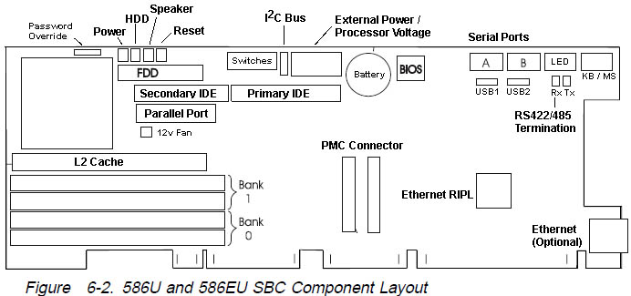
IDE Controller
The 586/586E has two IDE connectors: a primary and
the secondary controller (40 pin). Each controller
supports two drives and can operate in PIO modes 0 through 4 and DMA
modes 0 through 2. These interfaces support transfer rates of up to
16.7 MB per second,
100 MHz Pentium
133 MHz Pentium
166 MHz Pentium
200 MHz Pentium
L2 Cache
The SBC has a single socket for the level-2 (L2) cache.
This socket
can be populated with a 512 KB cache module. L2 cache is not required
for proper operation on the SBC. If L2 cache is not installed, the SBC
operates using the internal cache on the microprocessor.
76H4390 256 KB cache memory module
76H4391 512 KB cache memory module
SIMMs
The SBC has four 72-pin SIMM sockets organized into two
banks of
memory. These sockets can accept gold-tabbed, 60-ns, EDO parity SIMMs.
These SIMMs can be 4 MB, 8 MB, 16 MB, 32 MB, or 64 MB. Each bank of
memory must contain a pair of SIMMs identical in size, speed, and
technology. The SIMMs do not have to be the same from one bank to
another; the SBC will optimize for the maximum performance of each bank.
76H4386 4 MB memory SIMM, 60-ns EDO, parity, gold tab
76H4387 8 MB memory SIMM, 60-ns EDO, parity, gold tab
76H4388 16 MB memory SIMM, 60-ns EDO, parity, gold tab
76H4389 32 MB memory SIMM, 60-ns EDO, parity, gold tab
20L2651 64 MB memory SIMM, 60-ns EDO, parity, gold tab
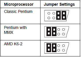
Processor Voltage Selection Jumpers
These jumpers are supported on the 586U and 586EU SBCs only. They
select the input voltages supplied to the microprocessor. The following
shows the pin location and jumper settings for each microprocessor
type. Additional power is not required if the SBC is plugged into a
backplane that supports the PICMG standard.
Attention! 586U/586EU ONLY! Installing
external power jumpers on 586/586E will damage the SBC!
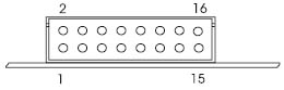
External Power Connector - 586U and 586EU
| Pin |
Description |
Pin |
Description |
| 1 |
Used for jumper |
2 |
Used for jumper |
| 3 |
Used for jumper |
4 |
Used for jumper |
| 5 |
Used for jumper |
6 |
Used for jumper |
| 7 |
Used for jumper |
8 |
Used for jumper |
| 9 |
+5 V |
10 |
Ground |
| 11 |
+5 V |
12 |
Ground |
| 13 |
+5 V |
14 |
Ground |
| 15 |
+12 V |
16 |
-12 V |
Remove Power-on or System Administrator Password
1. Turn off the computer and remove the cover.
2. Use a screwdriver or other conductive device to short the two pads
on the password clear pad for 10
seconds. An alternative method is to remove the battery for 10 minutes.
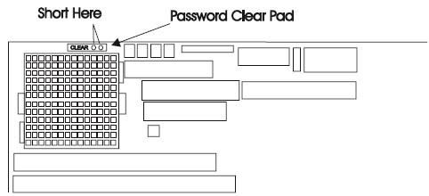
3. Reinstall the cover.
4. Turn on the computer and run the Configuration/Setup Utility program.
5. If a password is required, you must enter a new one.
Clear CMOS
The two pads are at the other upper edge of the CPU socket.
Watchdog Timer and Thermal Monitor
These two functions provide monitors that detect certain processing
conditions (watchdog interrupt) and
over-temperature conditions (thermal interrupt). They are available
only on the 586U and 586EU SBCs.
To use these functions, you need to install the device drivers and
other support programs, which can be
downloaded from the Web site (see “Downloading System Support Programs
and BIOS Updates” on
page 8-2 for more information). The downloaded files include sample
programs.
Watchdog Timer:
The watchdog timer allows software to recover from fatal
errors and log status information about the error conditions. During
operation, the watchdog timer is reset at specified intervals. If the
timer is not reset before the timer reaches the end of the interrupt
period, the timer generates a watchdog interrupt. When the support
program is loaded, the system can be programmed to perform one of the
following when a watchdog interrupt occurs:
Ÿ Generate a hardware reset (similar to turning off the computer)
Ÿ Generate a nonmaskable interrupt (NMI)
Ÿ Generate a hardware interrupt (PCI INT C)
Thermal Monitor: The thermal
monitor is used to detect an internal over-temperature condition. It
monitors the temperature of the microprocessor and the temperature
inside of the computer. With the monitor program loaded and running,
the monitor can be programmed to generate a hardware interrupt if
either temperature exceeds its programmed value.
Power-On LED
This 2-pin connector on the SBC provides input to the
system power-on indicator. It turns on the LED whenever 5 volts is
applied to the SBC. The connector is attached through a cable to the
system power-on LED (green).

HDD Access LED
This connector will drive a hard-disk-drive-accessed LED. It will light
the LED whenever there is activity to either of the IDE ports. The
connector connects through a cable to the HD-access LED (yellow).

J14 Reset Switch
This connector is used with a system reset switch. When the two pins
are shorted together, the SBC performs a hardware reset. The connector
is a 2-pin header attached through a cable to the backplane. When used
in stand-alone mode, this connector can be attached to a system reset
switch.

Speaker LED
This 2-pin connector on the SBC is used to drive a
speaker or an LED. A standard PC-class speaker can be connected to this
connector and it will give the normal system audio outputs. The speaker
connector is attached through a cable to the system speaker LED.
Hex Display
The SBC provides a two-digit hex display, viewable from the top of the SBC.
This display gives codes indicating the progress of POST. When the SBC has
completed POST successfully, the display shows a 00, and the operating system
starts loading. If an error is detected during POST, the error code is
indicated in the hex display, as follows:
1. The start code of EE
2. The first two digits of the error code
3. The second two digits of the error code
4. The end code of EE
For example, if a 162 configuration error occurred at power-on, you
would see EE 01 62 EE in the
hex display. This will repeat until you press a key.
Note: The 162 error will not
display when the SBC is set to auto-configure mode. In auto-configure
mode, the SBC automatically reconfigures itself and reboots.
76H4385 Remote-IPL chip (for SBC with Ethernet only)
|