|
SSA Adapter Front 32H2318
![Front [P]](/other/img/photo.gif)
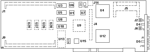
The 4-D resembles the 4-G on the front as to components and layout. The
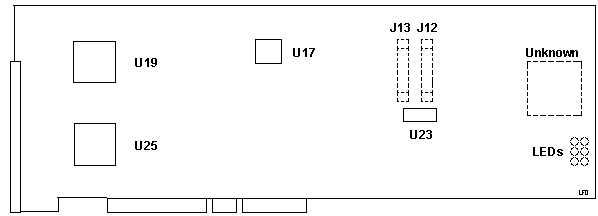
backs differ in the layout for J12-13 and the outlines for a big FPGA and LEDs.

D4 Status LED Loop B
D5 Status LED Loop A
J1,9 Pads for SIMM sockets
J2,6 Internal SSA ports
J3 "B2" SSA Loop B Port 2
J4 Pads for 140-pin connector
J5 Pads for cache socket
J7 "B1" SSA Loop B Port 1
J8 "A2" SSA Loop A Port 2
J10 "A1" SSA Loop A Port 1
J14 PS/2 Serial Port (Unknown) (really?)
TH1 PTC Resistor
|
U1 96H9834
U2 50.0000 MHz osc
U3,5,8,10 TC559128AJ-20
U4 Xilinx XC4413-PQ240C 6070 (HardWire)
U6 31H8637 BIOS Odd?
U7 Phillips SCC2691AC1A28
U9 Pads for 88G6298
U12 34G1521 "Miami" MCA iface
U13 Pads for Dallas DS1225AD-170 8Kx8 NVRAM
U14 40.000 MHz osc
U15 31H8636 BIOS Even?
U26-29 TC559128AJ-20 DRAM (really?)
|
SIMMs in J1 & J9
I have both slots filled with 4 MB SIMMs, 1Mx36 70 ns 5.0 V, P/N
82G6981. These have ten chips on one side of the PCB. There are 4 M514400C-70SJ
(data) and one M512200-70SJ (parity) on each half.
Light Pipes on D4 & D5
Both LEDs are normal LEDs on the PCB. There are light pipes to
transmit the light to the outside.
Each pair of connectors has a green light that indicates the operational
status of its related loop:
| Status |
Meaning |
| Off |
Both SSA connectors are inactive. If disk drives or other SSA adapters
are connected to these connectors, either those disk drives or adapters
are failing, or their SSA links are not active. |
| Solid |
The light is on continuously when power is turned on to the adapter
and both ports for that loop are operational; that is, the devices connected
next to the adapter in the loop have power turned on to them, are connected
correctly to the adapter, and are operational. |
| Slow Flash |
The light flashes continuously if one of the ports is not operational.
That occurs when the cable to that port is not connected correctly or the
device connected next to the adapter in the loop is not operational. |
SSA Adapter Back
![Back [P]](/other/img/photo.gif)

J12,13 Pads for 40-pin connector
LEDs Pads for status LEDs?
U17 VLSI-ARM VY86C06040
|
U19,25 88H5516
U23 AM29F040-120EC
Unknown Pads for large QFP
|
40 MHz version of the ARM6 Application-Specific Standard Product (ASSP)
version of the new ARM processor, designed the VY86C06040, is pin-to-pin
compatible with lower clock frequency versions. It operates with a 40 MHz
clock and exhibits a peak performance of 40 MIPS and a sustainable performance
of 26 MIPS at 5.
|