|
Author: Fred Eady
Source: MicroComputer Journal, Nov/Dec 1995 (pages 60-67 physical)
As I was writing this article, I thought about how much I depend upon the
RS-232 standard every day. Without the RS-232 interface, you probably wouldn't
be able to get to and download text and code from the EDTP BBS and other
on-line services. My Internet and CompuServe e-mail simply wouldn't exist. And
all of the programmer kits that EDTP produces use an offshoot of the RS-232
standard to communicate with a host personal computer. Would you have been able
to use your computer yesterday to fax that special graphic or message? How
about those software updates you got from your software vendor's public
bulletin board? Could you get along without your daily dose of office
e-mail?
If you've ever stopped to think about what really lies behind all of this
telecommunication technology, you'll find here the answers that are hidden
within the ubiquitous RS-232 standard. I begin at the beginning—the origin of
the standard.
Computers Learn to Speak
In the beginning, computers of all sizes (most of them large to very large)
communicated via wire pairs that carried pure digital signals. This was
commonly termed digital or direct-current signaling. The maximum practical
distance data could be transmitted was only about a mile at a speed of only 300
bits per second (bps). This arrangement usually required computer or terminal
users to install special cable and locate regenerative repeaters every few
thousand feet to obtain reliable data communication. These primitive networks
rarely reached beyond the sites on which they were installed.
By current standards, this was a simple but expensive way to ship data
packets between computers and users. Even back, then some users saw this system
of digital communication as a major drawback for the future of large-scale
computing and digital telecommunication as a whole.
The idea to use the public common carrier system (voice telephone
facilities) to send and receive digital data arose. After all, some sort of
telephone system was already in place almost everywhere on Earth. The
modem—or data set—was pressed into service.
A data set was placed at each computer site for the purpose of modulating
and demodulating digital signals that were transmitted between other remote
computers over the analog telephone system. This new "modulation and
demodulation" hardware was to become what we now know as the modem.
And Then There Was RS-232
With the advent of the modem, teleprocessing life was good, albeit
expensive, and everyone was making modems. In May of 1960, it was evident that
a standard was needed to identify the electrical interface between computer and
modem or data set. It was decided to establish a standard voltage with standard
signal parameters and a standard nomenclature to identify the conductors in the
cable that connected computer and modem.
Teleprocessing technology was booming, and more and more computers and
terminals built by various vendors needed to communicate with each other.
Without a standard, the whole teleprocessing industry could come to a grinding,
non-standardized halt.
As a result, a committee named the Electronic Industries Association was
formed. The EIA drafted a standard known as EIA RS-232(X). Though it was a
great idea, the original specification was broad in meaning and didn't
guarantee compatibility. (The new RS-232 specification also had a competitor
outside the United States, known as the CCITT, or Consultative Committee for
International Telephone and Telegraph, Recommendation V.24).
The RS-232 proposal defined a logical and physical interface between
computer equipment and a modem. Basically, two interfaces are really needed to
complete digital communication between a pair of computers and/or
terminals.
The computer or terminal port presents both a physical and a logical
interface to the modem and consists of several conductors for controlling,
transmitting and receiving data, and timing/clocking. For this discussion, the
interface between computer and modem has a set of standards and is referred to
as an EIA RS-232 interface.
The second interface provides the modem with a physical path to the
communication channel (telephone line, fiber-optic link, satellite, etc.). For
most personal-computer users, this communication channel is the two-conductor
analog telephone line.
The EIA standard originally identified seven interface conductors and no
specific connector. Signal voltages were defined as at least ±3 volts
but not greater than 20 volts with respect to ground.
In October 1963, RS-232 became RS-232-A and was modified to include a 25-pin
connector with a maximum cable length of 50 feet. This revision established
fixed relationships between a circuit and specific pin numbers. Also, an
alphabetic coding system for each type of interface circuit was presented. The
first character of the coding system designated A for ground, B for data, C for
control and D for clocking.
The original seven basic circuits and the signal-level definition of -3 for
mark and +3 for space were retained intact, adding ten additional optional
circuit definitions. The maximum permissible open-circuit voltage was changed
to 25 volts, and a current maximum between any two conductors, including
ground, was set at 0.5 ampere. Conductors that permit auto answer capability
were first introduced in this revision.
October 1965 brought about RS-232-B, which defined terminating impedances
that permitted circuit designers to build hardware with greater reliability.
Open-circuit signal levels remained unchanged at -3 to -25 volts as mark and +3
to +25 volts as space, but revision B added an important voltage specification.
By specifying that signal ground on pin 7 be tied to frame ground on pin 1 in
the modem, a definite signal reference is established between modem and host
computer or terminal.
This "Interface Between Data Terminal Equipment and Data Communication
Equipment Employing Serial Binary Data Interchange" specification was released
in August 1969. It further clarified conductor definitions and stated that
properly-terminated RS-232 circuits shall not exceed ±15 volts.
RS-232-C came along later and defined the interface between Data Terminal
Equipment (DTE) and Data Circuit terminating Equipment (DCE). DTE equipment is
normally a dumb terminal, intelligent device like a microcontroller or
intelligent workstation like a PC that's capable of providing a serial bit
stream. DCE equipment receives the DTE-generated bit stream via the RS-232
interface and converts it to a form that's suitable for transmission over a
telecommunication medium, such as voice-grade telephone lines.
If the RS-232-C standard is followed, physical DTE port connectors are male
and physical DCE port connectors are female. A PC's serial port is normally the
DTE device and the modem's port is usually configured as a DCE device.
A PC's serial port is male, whether it uses a nine- or a 25-pin connector.
The modem connector is most likely a female 25-pin connector. Although the
nine-pin connector isn't an EIA RS-232 standard, today it's a commonly used
RS-232 physical interface. The nine-pin interface first appeared commercially
on AT-class PCs in the early 1980s.
RS-232-C also provided specifications for communication over voice grade
lines, at speeds up to 9,600 bps. This allowed for high-speed asynchronous
point-to-point communication over the public switched telephone network at that
time.
RS-232-C defines 21 circuits on the interface. Table 1 is a summary
of the RS-232-A, -B and -C pin descriptions.
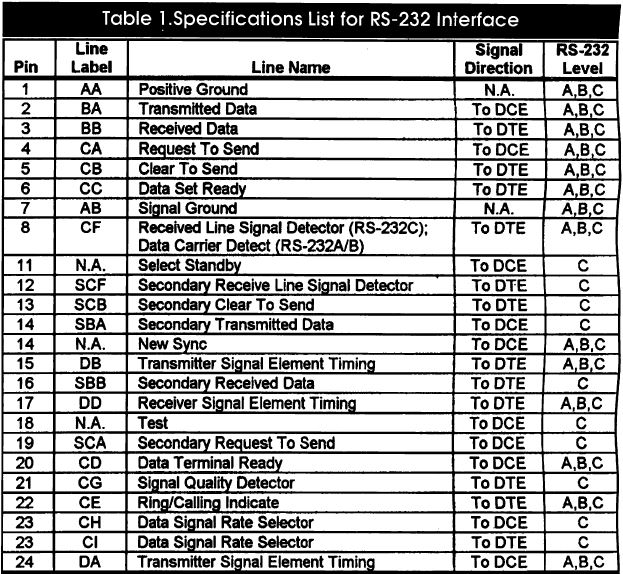
Table 1. Specifications List for RS-232 Interface
During data transmission, the mark condition denotes the binary-1 state and
the space condition denotes the binary-0 state.
For timing and control interchange circuits, the function shall be
considered ON when the voltage is more-positive than +3 volts and shall be
considered OFF when the voltage is more-negative than -3 volts, both with
respect to signal ground. The function isn't defined if the voltages are within
the transition region between -3 to +3 volts with respect to signal ground.
Mark and space are commonly used in specification sheets to describe the
condition of an RS-232 data or control line. Figure 1 defines the
minimums and maximums of the RS-232-D and V.28 specifications and as some of
the termination specifications.
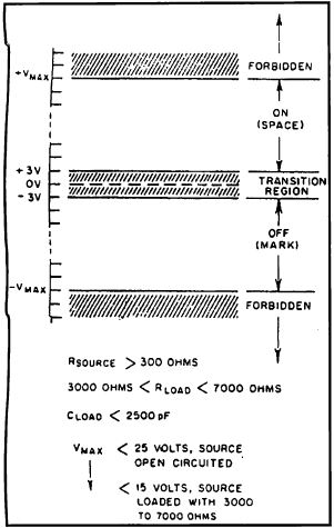
Figure 1. Minimum and maximum specifications for RS-232D and V.28
Today, the majority of commercially available equipment is based on the
RS-232-C or RS-232-D standard. (The CCITT V.24 and V.28 standards are also
common and widely used.) Many of the RS-232 circuits don't have to be used to
in a communication session between two terminals or computers. Refer to
Table 2 and Table 3 as I describe the purpose of the most
commonly used RS-232 data interface connections.
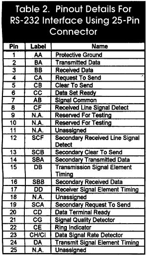
Table 2. Pinout Details For RS-232 Interface Using 25-Pin Connector
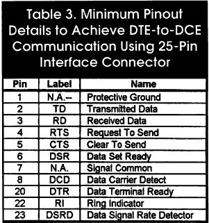
Table 3. Minimum Pinout Details to Achieve DTE-to-DCE Communication Using 25-Pin Interface Connector
RS-232 Circuit Description
The first thing you'll notice is that Table 3 lists only 11 of the 25
possible RS-232 lines as those required to complete a DTE-to-DCE communications
session. In most cases, you can also omit the Data Signal Rate Detector and
Protective Ground circuits. This leaves nine connections.
Remember that RS-232 is a standard interface specification and can be used
for a variety of other purposes, such as synchronous communication and
protocols that require additional clocking and timing. In reality, you can have
a working DTE-to-DCE conversation using only three of the 11 lines shown in
Table 3. If the DTE and DCE utilize custom-written software, only TD, RD and
signal ground are required to move data along the three-conductor link.
Here's a rundown of the definitions of the 11 pins that almost everybody
uses:
- Pin 1 (Protective Ground Circuit, AA). This conductor is bonded to
the equipment frame and can be connected to external grounds if other
regulations or applications require it.
- Pin 2 (Transmitted Data Circuit BA, TD). This is the data signal
generated by the DTE. The serial bit stream from this pin is the data that's
ultimately transmitted by the modem or decoded by an intelligent DCE
device.
- Pin 3 (Received Data Circuit BB, RD). Signals on this circuit are
generated by the DCE. The serial bit stream originated at the remote DTE and is
a product of the receive circuitry of the DCE. This is usually digital data
that's produced by an intelligent DCE or modem demodulator circuitry.
- Pin 4 (Request To Send Circuit CA, RTS). This signal prepares the
DCE for a transmit operation. The RTS ON condition puts the DCE in transmit
mode, while the OFF condition places the DCE in receive mode. The DCE should
respond to an RTS ON by turning ON Clear to Send (CTS). Once RTS is turned OFF,
it shouldn't be turned ON again until CTS has been turned OFF. This signal is
used in conjunction with DTR, DSR and DCD. RTS is used extensively in flow
control.
- Pin 5 (Clear To Send Circuit CB, CTS).This signal acknowledges the
DTE when RTS has been sensed and data can be transmitted. Data is transmitted
across the communications medium only when this signal is active. This signal
is used in conjunction with DTR, DSR and DCD. CTS is used in conjunction with
RTS for flow control.
- Pin 6 (Data Set Ready Circuit CC, DSR). DSR indicates to the DTE
that the DCE equipment is connected to a valid communication medium and, in
some cases, indicates that the line is in the OFF HOOK condition. OFF HOOK is
an indication that the DCE is either in dialing mode or in session with another
remote DCE. When this signal is OFF, the DTE should be instructed to ignore all
other DCE signals. If this signal is turned off before DTR, the DTE is to
assume an aborted communication session.
- Pin 7 (Signal Common Circuit, AB). This conductor establishes the
common-ground reference for all interchange circuits, except Circuit AA,
protective ground. The RS-232-B specification permits this circuit to be
optionally connected to protective ground within the DCE as necessary.
- Pin 8 (Data Carrier Detect Circuit CP, DCD). This pin is also known
as Received Line Signal Detect (RSLD) or Carrier Detect (CD). This signal is
active when a suitable carrier is established between the local and remote DCE
devices. When this signal is OFF, RD should be clamped to the mark state
(binary 1).
- Pin 20 (Data Terminal Ready Circuit CD, DTR). DTR signals are used
to control switching of the DCE to the communication medium. DTR ON indicates
to the DCE that connections in progress shall remain in progress, and if no
sessions are in progress, new connections can be made. DTR is normally turned
off to initiate ON HOOK (hang-up) conditions. The normal DCE response to
activating DTR is to activate DSR.
- Pin 22 (Ring Indicator Circuit CE, RI). The ON condition of this
signal indicates that a ring signal is being received from the communication
medium (telephone line). It's normally up to the control program to act on the
presence of this signal.
- Pin 23 (Data Signal Rate Detector Circuit CH/CI, DSRD). Circuit CH
is the DTE component, CI the DCE component. Signals on this circuit are used to
select between the two data signaling rates in the case of dual-rate modems. ON
selects the greater of the two rates.
- DTE is powered up and DTR is asserted.
- DCE is powered up and senses the DTR from the DTE.
- DCE asserts DSR. The modem goes off-hook.
- If the line is good and the other end is ready, the carrier is detected and the DCE asserts DCD.
- The DTE raises RTS.
- The DCE responds with CTS.
- The communication session is established. The control program transmits or receives data.
A typical answer sequence would go something like this:
- The DTE has the DTR asserted.
- The DCE is in auto-answer mode, with DSR asserted.
- The remote station calls DCE emits RI.
- The DTE senses RI. The control program takes control. The DCE goes off-hook.
- The DCE negotiates with the remote DCE, and DCD is asserted.
- Depending upon the control program, RTS is asserted or the DTE waits for data.
- The DCE responds with CTS.
- The communication session is established.
In the early days, half-duplex communication dominated, mainly because of
the communication protocols and hardware that existed at that time. In
half-duplex, data can travel in only one direction at any given time. For
instance, on a two-conductor telephone line, one computer would transmit while
the other received and vice-versa. In combination with the hardware, the
half-duplex software protocol determined which end was to receive or
transmit.
Full-duplex protocol permits transmission and reception without regard to
who is talking and who is listening at any given time. To achieve full duplex
operation required two pair of telephone conductors, one pair each for transmit
and receive. Of course, the transmit pair at the local end was connected to the
receive pair at the remote end and the local receive pair was connected to the
remote transmit pair.
Two-conductor half-duplex and four-conductor full-duplex implementations
remain even today, but two conductor full-duplex communication is now the norm.
Full-duplex two conductor communication is the child of advanced frequency- and
phase modulation techniques contained in modern modems.
Table 4 details the pseudo-standard AT nine-pin interface.
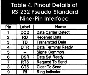
Table 4. Pinout Details of RS-232 Pseudo-Standard Nine-Pin Interface
Asynchronous Data Packet
Assuming you have RS-232 standards implemented, four other parameters are
important to obtaining a successful asynchronous communication session. These
are baud rate, number of data bits, number of stop bits and parity bit. If
necessary, a parity bit can be added. However, for simplicity, most
asynchronous links don't use one. Parity is primarily used to help ensure data
integrity on critical links. The downside to parity is that if your data packet
gets trashed, you won't recover the data, no matter what parity scheme you have
in place.
A typical transmitted packet of data consists of a start bit, eight data
bits and a stop bit. The other most-common combination is seven data bits with
even parity and one stop bit.
The width of each bit determines the baud rate. For example, for a 9,600-bps
link, each bit width is 104 ps, arrived at by equating 9,600 to frequency and
104 ps to period and applying the formula P = 1/F, where P is period in seconds
and F is frequency in Hz. In advanced protocols, baud rate can also be measured
by the number of phase transitions in a given period of time.
In asynchronous serial transmission, first to be transmitted is the start
bit. This bit permits the receiving DTE to synchronize with the transmitting
DTE. The start bit is a logic 0 space that lasts for exactly one bit period.
The link should always be in a mark, or 1, state before the start bit is
sent.
Once the receiving DTE senses a start bit, it waits exactly 1.5 bit periods,
or 156 ps for 9,600 bps, before sampling the status of the link. The idea is
for the receiving DTE to sample each bit frame as close to the center of the
timing frame as possible. After the first 1.5-bit period wait, the receiving
DTE reverts to sampling the incoming bit stream at the standard
104-ps-per-frame rate. If everything goes as planned, the rest of the data byte
will be sampled near the center of each bit time.
A stop bit (mark) signals the end of the character transmission. One or two
stop bits are normally used to end a transmission. This entire process—start
bit, data, stop bit—repeats itself for every character transmitted,
eliminating any probable cumulative timing skew.
8250 & 16550 UARTs
The heart of the serial port is the UART, or Universal Asynchronous Receiver
Transmitter. The original personal computers used the INS8250 family of UARTs.
Most high-speed RS-232 interfaces today contain the 16550 UART. The 16550 is a
high speed buffered version of the 8250.
Fundamental operations performed by the 8250 and 16550 are almost identical.
Serial ports on a PC are named COM1 through COM4.For this discussion, assume
all references are relative to COM1 at address 3F8h. These UARTs use a register
map to simplify implementing serial algorithms. Let's dissect the 8250 and
16550 register-by-register:
Receiver Buffer Register. Figure 2 logically depicts
Register 0, which is Receiver Buffer Register, or RBR. When a character is
received by the UART, it's assembled and placed in the RBR. This assembled
value can be read by performing a read operation at address 3F8. This register
is identical to the 16550 RBR.
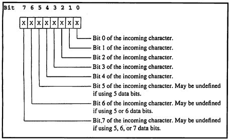
Figure 2. Receiver Buffer Register
Transmitter Holding Register. This register shares the address of
the RBR and is addressed by writing to address 0x3F8. As shown in Figure
3, the THR is used to transmit a character out of the RS-232 interface.
This register is duplicated in the 16550.
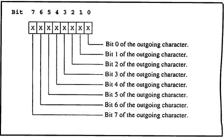
Figure 3. Transmitter Holding Register
Interrupt-Enable Register. As its name implies, the IER is used
to enable interrupts and is located at address 0x3F9. Again, this register is
the same one in the 16550. Note in Figure 4 that the interrupt
capability of this device permits use of these UARTs in multitasking
environments.
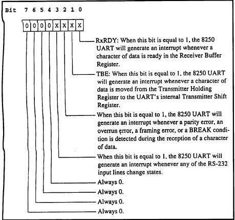
Figure 4. Interrupt-Enable Register
Interrupt Identification Register. This register is located at
0x3FA and is used to determine what interrupt has occurred. The 8250 version of
this register is shown in Figure 5. Note the ability of this register to
enable or disable the FIFOs (first-in, first-out) for the 16550 in Figure
6. In the 8250, this is a read-only register. In the 16550, you can also
write to this register to set FIFO operation. When writing to this register,
use address 0x3FA.
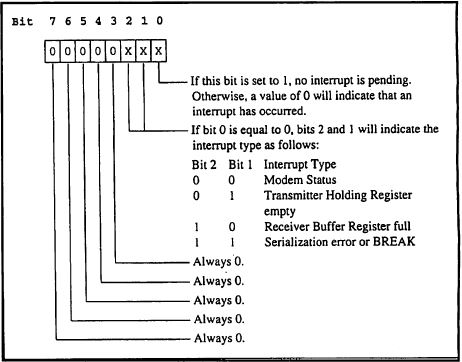
Figure 5. Interrupt-Identification Register for 8250
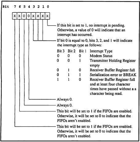
Figure 6. Interrupt Identification Register for 16550
When used for setting FIFO operation, this register is called the FIFO
Control Register, or FOR. The FOR is depicted in Figure 7.
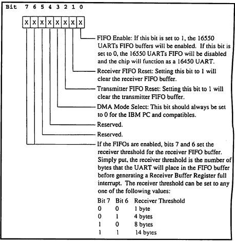
Figure 7. FIFO Control Register
Line-Control Register. This register is used to set the number of
data bits, number of stop bits and parity bit, to name a few. This read/write
register is located at 0x3FB. The 16550 register is equivalent and is shown in
Figure 8.
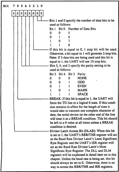
Figure 8. Line-Control Register for 16550
Modem-Control Register. Another read/write register, the MCR sets
DTR and RTS and enables interrupts. Figure 9 represents the MCR register
for both the 8250 and 16550. The MCR is addressed at 0x3FC.
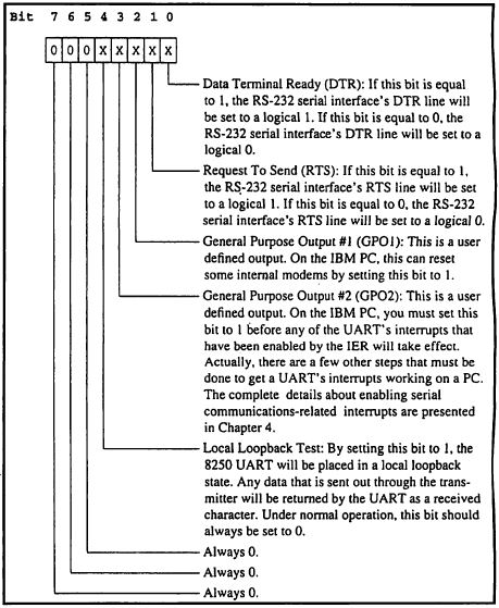
Figure 9. Modem-Control Register
Line-Status Register. The LSR is used by the UART to report
availability of received data, errors and transmission-complete condition. The
contents of this register, shown in Figure 10, are read from location
0x3FD. The 16550 version of this register, shown in Figure 11, includes
a FIFO error bit.
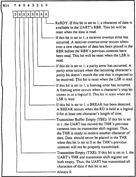
Figure 10. Line-Status Register for 8250
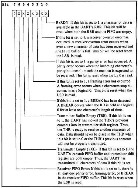
Figure 11. Line-status register for 16550
Modem-Status Register. This register is read to obtain the
current states of the CTS and DSR lines and indicates the current state of the
DCD and RI. Figure 12 details the bit structure for both the 8250 and
16550. The MSR is addressed at 0x3FE.
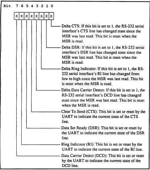
Figure 12. Modem-Status Register for 8450 (??? -LFO)
Baud-Rate LSB-Divisor Latch Register. The DLL is used to set the
least-significant bit of the baud rate divisor. To obtain access to this
register, you must set the LCR DLAB bit to 1. By virtue of the DLAB bit, this
register shares the location 0x3F8 with the RBR and THR. The baud-rate divisor
is calculated by dividing the desired baud rate into 115,200 decimal. The lower
eight bits of the result are placed in the DLL. Figure 13 shows the bit
layout of this 16550/8250 register.

Figure 13. Baud-Rate LSB-Divisor Latch Register
Baud-Rate Divisor Latch Register. The high-order eight bits of
the baud-rate divisor result are loaded into this register. The DLM shares
0x3F9, the IER, in the same way the DLL shares 0x3F8. This register is
identical in the 8250 and 16550. Figure 14 describes this one.
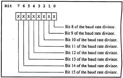
Figure 14. Baud-Rate Divisor Register
Remember that the UART signal levels are TTL and must be converted to RS-232
levels with special voltage translation ICs like the MAX232 or MAX233 before
being presented to the RS-232 interface.
Modems
I won't spend a lot of time on this topic because most of you have set up
and used a modem. The most-important thing to know about today's modems is how
to communicate with them. Hayes instituted a standard with its AT command set.
Essentially, AT comes from ATtention. If you bring up your favorite
communications program to a blank screen and type in AT, the modem should
return OK. You can then use the many AT commands to initiate a dial sequence,
set data compression modes and control RS-232 control signals like DTR, RTS and
DSR.
The AT commands vary from modem to modem and are detailed in the manuals
that accompany each modem.
The best way to get a feel for the different compression schemes and
protocols is to try them. The EDTP BBS supports V.34, V.FC, V.32bis, V.32,
V.22bis, V.22 and V.21 international standards, as is the case for the Bell 103
and Bell 212A U.S. standards. It also supports MNP5 protocols for error
correction and data compression. Modem data rates are 28.8K bps down to 300
bps. Consult your modem and communications program manuals for details on how
to setup these protocols.
Sometimes, knowing exactly how RS-232 works isn't quite enough. When
designing new serial-based equipment, I use a sophisticated RS-232 data
monitor. Called a datascope, this device allows me to see and capture the
RS-232 signals and actual asynchronous data in realtime for analysis.
There's no need for the average user to carry a datascope when a breakout
box will suffice. A breakout box is a simple device that has LED indicators for
monitoring the status of the RS-232 interface. Breakout boxes are good for
determining if you have all of the proper signals needed to establish a
connection. Most commercial breakout boxes also permit RS-232 circuits to be
included, excluded and even tied together for special purposes.
If you wish to experiment with RS-232, the EDTP BBS offers numerous
communications routines written for a variety of microcontrollers. You'll also
find RS-232 routines written in C and Quick Basic for PCs.
|