|
Author: Bob Smith
Source: PC Tech Journal, vol 5, no 7, July 1987 (page 134+)
The 101-key enhanced keyboard, declared the standard for IBM's entire
line of PCs, introduces a fundamental difference in the hardware and software
interface to the system.
Staying power has never been the strongest attribute of IBM‘s keyboards.
With the introduction of almost every model in the PC line has come a new
version of the “standard" keyboard—that’s three keyboards in five years.
Worse, the differences between keyboards have been more than cosmetic,
involving some fundamental software incompatibilities; every new keyboard model
required that not only users, but also the software be retrained.
At last, IBM seems ready to end the frustration. The company has stated that
all of its personal computers and terminals will use one model: the 101-key
Enhanced Keyboard, introduced with the IBM RT PC in January 1986. The enhanced
keyboard was subsequently made available with the 8-MHz model of the PC/AT, the
XT-286, and the PC/XT models manufactured since April 1986. For reasons
explained later, this keyboard cannot be retrofitted to systems not designed to
support it.
Keyboard standardization received a boost with the introduction of the IBM
Personal System/2 (PS/2) line; all models come with the enhanced keyboard. In
fact, IBM has strengthened its' commitment to the enhanced keyboard by making
it the only model available for the PS/2 machines (For the AT, the older 84-key
model is available on special order as a no—cost option)
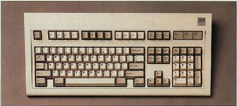
Photo 1: The 101-key Enhanced Keyboard
The enhanced keyboard has a dedicated cursor keypad and twelve function
keys.
The most obvious differences in the enhanced keyboard from previous models
are the set of additional dedicated cursor control keys between the original
numeric/cursor control keypad and the typewriter section, the line of function
keys (12 instead of 10) across the top, and the shift state indicator lights.
Photo 1 shows the layout of the enhanced keyboard.
Actually, the enhanced keyboard comes in two versions: a 101-key and a 102-key
layout. The latter, available only outside of the US, is referred to in IBM
documentation as the WT, or World Trade keyboard. It has an additional
alphabetical key nestled in the crook of the Enter Key, which is a larger,
hook-shaped key on the WT; the backslash is located between the Z and the left
shift key (as on the original PC keyboard), To support a variety of national
languages, the WT keyboard is available with several different layouts of the
alphabetic keys.
According to IBM documentation, the U.S. and WT versions of the enhanced
keyboard are identical at the software level. The setup program for the PS/2
models cannot distinguish between them; instead; it asks the user to identify
the keyboard by indicating the shape of the Enter key.
System Interface
An overview of the enhanced keyboard interface, and its difference from
previous models, can best be presented in terms of the incremental changes
introduced to that interface with each keyboard model since the original
PC.

Figure 1: PC Processing
The PC introduced the concept of translating keystroke data into character
codes and extended key codes. It applied one level of translation.
Figure 1 shows the steps involved in
processing keyboard input on a standard PC or AT. Each keystroke sends to the
keyboard controller a one-byte scan code, which is a number uniquely
identifying the key. The controller places the scan code unchanged in its
output buffer, and generates a hardware interrupt that causes the processor to
execute an interrupt 09H.
The interrupt service routine (the default interrupt 09H handler is in the
ROM BIOS) looks up the scan code in its internal tables and translates it into
a two-byte code. In most cases, one of these bytes is the original scan code
and, if the key represents an ASCII character, the other is the ASCII code. For
non-ASCII characters, the second byte is usually zero.
This two-byte code is placed into the next available location in the
circular keyboard buffer, where it waits to be read by an input request from a
program. Keyboard read requests are processed by the interrupt 16H handler,
which reads the two-byte key codes from the buffer and passes them unmodified
to the requesting program.

Figure 2: 84-key Processing
The first AT keyboard added another layer of translation at the level of the
keyboard controller. Above that, the data are the same as in the PC.
The 84-key keyboard introduced with the first model of the AT has a
different key layout and produces scan codes distinct from those of the
original 85-key PC keyboard. The scan-code sets on the two keyboards are
different because, for reasons of physical circuit design, it is most efficient
to assign scan codes by key location. To maintain compatibility at the software
level, IBM introduced a preliminary scan-code translation at the controller
level, shown in Figure 2. After
translation, the controller's output for a given key is the same as that
key‘s output from a PC keyboard controller, thus the interrupt 09H handler
and all subsequent software see the same set of key codes as on the original
PC.

Figure 3: 101-key Processing
The enhanced keyboard added the capability of switching scan-code sets.
Recognizing the new keys requires enhanced support to be present in the
keyboard routines of the BIOS.
The 101-key enhanced keyboard introduced yet another key layout. Instead of
merely coming up with a new set of scan codes for the new layout, IBM came up
with three. By default, the scan-code set made active at boot—up is, for the
most part, the same as produced by the 84-key model and is translated by the
controller in much the same fashion. Differences arise because the enhanced
keyboard produces output for the additional keys not present on the previous
models. As shown in Figure
3, these differences are handled by an additional translation step at the
other end of the process, within the interrupt 16H handler that passes the
two-byte codes out of the keyboard buffer to the requesting program.
The enhanced keyboard adds flexibility at two levels. First, the basic scan
codes it produces at the keyboard end of the process are not fixed, but can be
chosen from three sets. Second, the output at the other end of the process is
filtered through an additional layer of translation. Customized programs can
modify either or both ends of the process to modify the transformation of
keystrokes into program input.
The differences between the enhanced keyboard and previous models go much
deeper than layout and key count. One immediately noticeable difference is
that, at boot-up, the enhanced keyboard is put in the NumLock state. This
change from past behavior adds to the hardship of transition to the new layout.
It is a minor symptom of the many changes made to the keyboard itself and to
its interface with the support software, but it can be easily remedied. The
following program turns off the NumLock bit in the shift status byte that the
BIOS uses when reading keystrokes.
MOV AX,A0H
MOV DS,AX
AND BYTE PTR [17],0DFH
RET
It can be assembled into a .COM file (a debugger is more practical than an
assembler) and then invoked from the AUTOEXECBAT file.
BIOS Interface
The enhanced keyboard can be used only with systems that support it with an
enhanced interrupt 16H handler in the BIOS. According to IBM documentation,
this includes the following models: the AT with the BIOS dated 11/15/86 and
later; the XT with the BIOS dated 1/10/86 and later; the XT-286; and all of the
PS/2 models The enhanced BIOS routines support 70 new ASCII/scan code pairs as
listed in Table 1. Some of
these codes are the result of the new keys that are present on the enhanced
keyboard (F11, F12, and the additional cursor control keys), while others add
support for combinations of keys that were present but not recognized on
previous keyboards (for example, Ctrl-up arrow, Ctrl-down arrow, and 5 on the
numeric keypad).
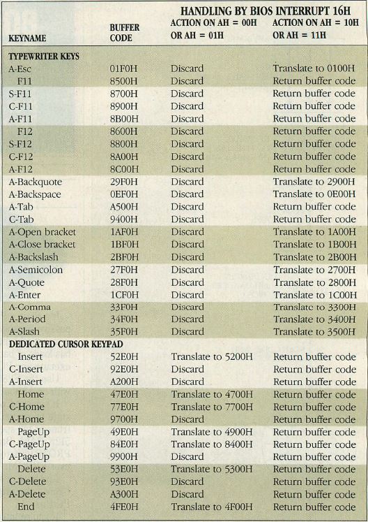
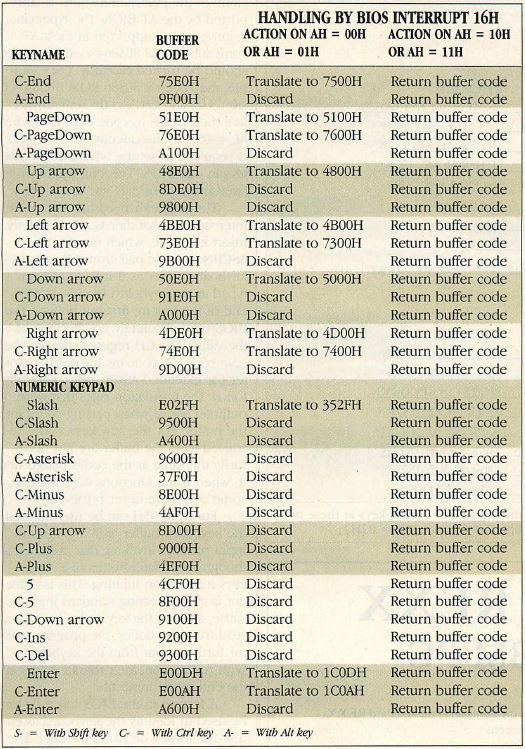
Table 1: Handling of New Keys by BIOS Interrupt 16H
For compatibility with programs that cannot handle the enhanced keys, the BIOS
translates or discards key codes unless requested through an enhanced
function.
In describing the keys on the right-hand side of the various keyboards, the
following terminology will be used. Cursor control keys on the original numeric
keypad will be named without prefix, such as Home or Del. Other keys around the
keypad will be prefixed with “Pad-“, as in Pad-Enter or Pad-asterisk.
Finally, the dedicated cursor control keys between the keypad and the
typewriter section will be prefixed With X, as in X-up arrow and X-End.
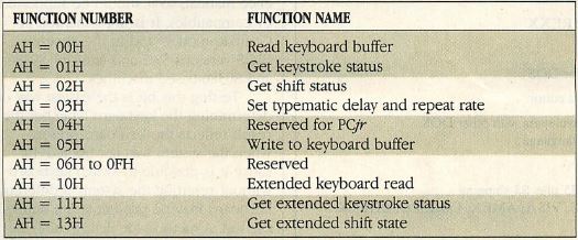
Table 2: BIOS Interrupt 16H Functions
The enhanced interrupt 16H handler recognizes eight functions; the last three
deal specifically with the keys unique to the enhanced keyboard.
The functions provided by the enhanced interrupt 16H handler are summarized
in Table 2. Two functions
are used for reading characters from the keyboard buffer (AH = 00H and AH =
10H) and two are used for determining the presence of characters in the buffer
(AH = 01H and AH = 11H). For keys that are common to both the 84-key and
101-key keyboards, each pair of functions operates identically. But their
action is different for keys that are present only on the enhanced keyboard.
The handling of the new keys by the standard and enhanced functions is listed
in Table 1. This information
is not formally documented; it was determined by reading the BIOS listings and
verifying it with test programs.
When a standard function encounters an enhanced key code, the code is either
discarded or, if it duplicates one of the standard keys, is translated to a
standard key code. Thus, the codes for pad-Enter and pad-slash are translated
to the codes for Enter and slash in the standard set of keys. If, for example,
F11 is the only key in the buffer and an AH = 01H call requests buffer status,
the response is that no keys are present in the buffer. Unfortunately, that
response turns out to be true because, after the call, there are in fact no
keys in the buffer - the F11 key gets deleted by the status call. The effect is
that programs not written for the enhanced keyboard see nothing different when
keys specific to the enhanced keyboard are pressed. That approach is overly
conservative because all programs should be written to handle unknown
keystrokes. Furthermore, this unconditional deletion of keys can create
problems even for programs that use only the enhanced BIOS functions.
When the enhanced functions (AH = 10H and AH : 11H) are used, however,
enhanced key codes are never deleted; they are either passed through unchanged
or translated as indicated in Table 1. The encoding of the new
keys exhibits a structure designed for efficient handling by both the standard
and enhanced keyboard reading functions of interrupt 16H. Except for a few
special cases, a code in the keyboard buffer represents one of the new keys if
its low-order is 00H or F0H, or the high-order byte is greater than 84H. A
low-order byte of E0H is assigned to new keys that duplicate the functions of
existing keys, such as those on the dedicated cursor control keypad. A
low-order byte of F0H is assigned to keys that exist on the 84-key keyboard but
are ignored by earlier versions of the BIOS, such as Pad-5 and Ctrl-up arrow, A
high-order byte greater than 84H is used for totally new keys, such as F11 and
F12.
The translation rules for new keys, when read with functions
AH = 0CH and AH = 01H, are as follows:
- If high byte > 84H, discard the entry;
- If low byte = F0H, discard the entry;
- If low byte = E0H, set low byte to 0 and return that
entry.
The exceptions are E00DH (Pad-Enter), which is translated to 1C0DH (Enter);
E00AH (Ctrl-Pad-Enter), which is translated to 1C0AH (Ctrl-Enter or LF); E02FH
(Pad-slash), which is translated to 352FH (slash); and 00E0H (Alt-Pad 224,
Greek alpha) and 00F0H (Alt-Pad 240, triple horizontal line), which are
returned unchanged.
For functions AH = 10H and AH = 11H, the rules are simpler. If the low-order
byte is F0H, it is changed to 00H and returned; all other key codes are
returned unchanged. These codes represent keys present on the standard
keyboard, but recognized only by the enhanced BIOS functions.
To take advantage of these new ASCII/scan—code pairs, programs must use
the extended interrupt 16H BIOS functions, AH = 10H and AH = 11H. Requesting
input through DOS will not work because DOS is not sensitive to the enhanced
keyboard - it uses the standard low-numbered calls only. Surprisingly, this is
true even for version 3.5 (specifically written to support the PS/2 series,
which requires the enhanced keyboard). However, using the BIOS instead of DOS
calls for keyboard I/O means that the input redirection facilities of DOS are
not available.
DOS calls to the keyboard routine cannot always be prevented; the resulting
behavior can be quite hard to diagnose. Suppose that a program consistently
uses the enhanced interrupt 16H functions so it can accept the extended
keystrokes. However, if the user presses any enhanced key while the system is
displaying characters on the screen, that keystroke is lost. Where did it go?
When running with BREAK ON, DOS checks for Ctrl-Break and Ctrl-C each time it
outputs a character to the display. It does so by requesting keyboard status
with interrupt 16H function AH = 01H, thus deleting all leading extended
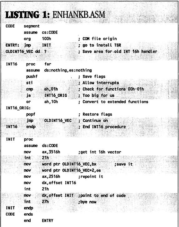
keystrokes from the buffer. One solution to this problem is to install a
customized interrupt 16H handler that converts all AH = 00H and AH = 01H calls
to AH = 10H and AH = 11H respectively. Listing
1 shows such a program. With the customized handler installed, it becomes
possible to use DOS calls in programs that need to receive the enhanced keys,
thus restoring the input redirection capability.
Listing 1: ENHANKB.ASM
The enhanced interrupt 16H handler also has two functions that return the
Shift-key status. Function 2 returns the standard status byte, the same one as
this function did in all versions of the BIOS keyboard routine. The enhanced
function (AH : 12H) returns two bytes of shift status information. The meaning
of the bits in both bytes is shown in Figure 4. Because the enhanced
keyboard has two Ctrl and two Alt keys, the extended status information allows
programs to distinguish which of the two Alt or Ctrl keys is being pressed.
Furthermore, status bits are available to determine if any of the three toggle
keys (CapsLock, ScrollLock, and NumLock) is being held down. In the standard
shift status byte, the bits for these keys just reflect the current state of
the toggle, not the actual position of the key. Note that the position of the
fourth key often used as a toggle, Ins, is not reflected in the status
bits.
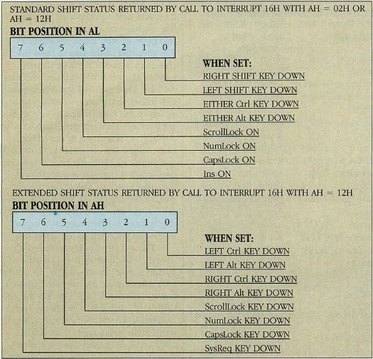
Figure 4: Keyboard Shift Status Bytes
The BIOS maintains an accurate record of the position of certain keys in these
two bytes. They are returned in AX from interrupt 16H function AH = 02H.
The interrupt 16H function with AX = 0505H controls the typematic action of
the keyboard—that is, the rate at which keystrokes are repeated when a key is
held down (see “Rev Up the AT Keyboard,” Kevin M, Crenshaw, Tech Notebook,
May 1985, p. 39). This function is fully supported by the BIOS code in all AT
models, but it was not documented in the prologue to the interrupt 16H listing
in IBM’s Technical Reference Manual. The latest version of the BIOS
documentation (which covers the entire IBM PC line, from the original PC
through all the PS/2 models) now supplies this documentation. Two parameters
are controlled by the interrupt 16H function: the delay before the repeating
action begins, and the rate of repetition once it does begin. Both settings
must be specified even though only one is to be changed.
The typematic delay (after which typematic action begins) is changed by
setting register BH to a value between 00H and 03H (range-checked by the BIOS).
The values BH = 00H, 01H, 02H, and 03H correspond to delays of 250 milliseconds
(ms), 500 ms, 750 ms, and 1000 ms respectively. The typematic rate is set by
the value in BL; it is also range-checked and must be between 00H and 1FH.
Setting BL = 00H corresponds to 50 characters per second (cps); BL = 0BH
restores the default rate of 10.9 cps; and BL = 1FH slows the keyboard down to
2 cps. Many fine gradations are possible, but the repeating action cannot be
turned off.
This function requires AL = 05H. Support to control the typematic rate was
introduced in the PCjr BIOS, which defines subfunctions AL = 00H through 04H.
The enhanced keyboard’s typematic feature is unlike any of the PCjr’s, so
a new subfunction was defined. None of the PCjr subfunctions is supported by
the AT BIOS. The typematic feature, while supported in most AT compatibles and
80386-based machines, should be treated carefully. For example, the Phoenix
80386 ROM BIOS (version 3.03 and earlier) decrements AX and then jumps to code
that checks for AL = 05H. Consequently, AX = 0306H is required to set the
typematic parameters in that BIOS. This bug has been fixed in versions 3.04 and
later.
The final enhanced function of the interrupt 16H handler is AH = 05H, the
insert key code, which inserts the ASCII/scan-code pair from CX into the
keyboard buffer as if it had just been typed at the keyboard (that is, at the
end of the first-in, first-out buffer). The BIOS does absolutely no checking of
the value. The CH register contains the scan code; CL contains the ASCII
character (or extended ASCII code). Carefully follow the translation rules that
were outlined above when placing codes into the buffer. For the new keys, codes
retrieved from the buffer are not necessarily the same as the codes placed into
it; when using functions 00H and 01H, some codes are never retrieved.
Function 05H can be used to seed the keyboard buffer with a program’s
input prior to invoking that program, although the default buffer size of 15
keys may be too limiting. This is different from redirecting standard input
because, after all the key codes have been read from the buffer, the program
waits for further input from the keyboard. With redirection, the program hangs
at the end of the input file.
A feature in the BIOS interface can be used to identify the keyboard as
either the 84-key or 101-key model. The byte at address 40:96H of the BIOS data
area will have bit 4 set to 1, if the enhanced keyboard was detected on bootup,
or 0, if otherwise. This feature is documented in the latest BIOS reference
manual, so it should be supported by compatibles. It is implemented in Compaq
models and in the Phoenix BIOS versions 3.02 and later for 80286- and 80386-
based machines.
Testing this bit is the easiest way of determining the keyboard type, but
the result reflects the keyboard present when the system was last booted.
Because it is possible to switch keyboards without resetting the system, a
different keyboard may be present at the time of the test. A method for
determining the type of keyboard currently attached is described in a later
section.
The Keyboard Controller
Normally, communications between programs and the keyboard takes place by
way of the BIOS calls explained above. The BIOS routines perform the actual I/O
to the keyboard controller. Occasionally, programs might need to talk directly
to the hardware in order to perform functions not supported by the BIOS. One
example is in determining the type of keyboard attached.
The keyboard system consists of a Motorola 6805 microprocessor within the
keyboard and an Intel 8042 controller on the motherboard. Programs can
communicate with either chip. The only information on this subject is scattered
over several sections of the Technical Reference Manual; it is cryptic and
occasionally misleading. For example, the manual does not distinguish between
the keyboard and the controller, using the term keyboard to refer to either or
both the 6805 and 8042.
The 8042 keyboard controller on the motherboard directs communications
traffic between the system and the keyboard. The controller is implemented
identically in all models of the AT, regardless of the keyboard support present
in the BIOS. In the PS/2 models, the functions of the 8042 are a superset of
those in the AT. This article considers only the AT implementation.
The controller communicates with the keyboard via a serial link that
supports either an 11-bit protocol with parity checking or a 9-bit protocol
without it. The former is the format used by the AT keyboard, the latter by the
original PC keyboard. At boot-up, the keyboard is in the 11-bit mode, which
supports either the standard or enhanced AT keyboard. The controller can be
switched into 9-bit mode to support the original 83-key PC keyboard.
By default, the 8042 translates the scan codes it receives from the 6805 to
those recognized by the BIOS. The translation table is kept in ROM on the 8042
chip and is not accessible to programs; it is published in the Technical
Reference Manual. As each scan code is received, the 8042 interrupts the
processor. Both the translation and the generation of the interrupt can be
disabled by reprogramming the controller.
The system and 8042 communicate with each other via a status register, an
input buffer, and an output buffer. The 8042 also has a program-accessible
command byte that controls its actions. All are accessed via I/O ports. The
Technical Reference Manual also refers to additional components of the 8042: an
input port, an output port, and a test, input port. However, they are neither
directly accessible as I/O ports nor involved in the keyboard interface. The
input port contains the value of switch settings and jumpers on the system
board (such as the keyboard-lock and display-adapter switches). The output port
(which, despite its name, can be read from as well as written to) is used only
during system start-up and shutdown, while the test input port is used only for
hardware checkout.
The 8042 status register is a read only port located at I/O address 64H. Its
contents may be read at any time; the bit definitions are summarized in Figure 5. Its most important function
is to synchronize data flow between the controller and the system.
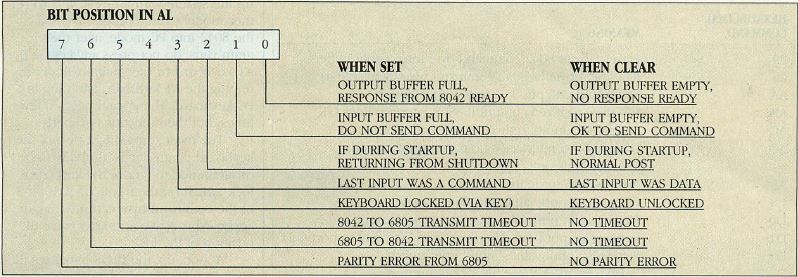
Figure 5: 8042 Status Register
A program can be used to determine the status of the keyboard controller at any
time by reading this byte from an I/O port.
The output buffer (from the 8042 to the system) is a read-only port located
at I/O address 60H. From it, the system can read the scan codes received from
the 6805 (after translation, if that feature is enabled) and responses to 8042
commands. An instruction to read this port should be executed only when the
status register indicates that the output buffer is full; at other times the
result is undefined. There is no clear indication as to how long the 8042 might
take to respond to a command to fill its output buffer. An 8-MHz AT waits for
about 1,200 ms for this condition, using a programmed delay loop. When the
system reads the output buffer, bit 0 of the status register (output buffer
full) is automatically cleared.
The input buffer (from the system to 8042) is a one-byte write-only port
that can be addressed as either I/O port 60H or 64H. Commands to the 8042 are
written to port 64H; data for the 8042 and for the 6805 are sent to port 60H.
Nothing should be sent to the input buffer unless the status register indicates
that it is empty. As with the output buffer, there is no clear indication as to
how long a program should wait for the 8042 to read its input buffer, but the
BIOS code for an 8-MHz AT uses a programmed delay loop of approximately 200 ms.
The OUT instruction to either port address automatically sets bit 1 (input
buffer full flag) of the status register. The 8042 resets the bit when it reads
the input byte.
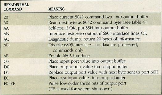
Table 3: 8042 Commands
The BIOS and other programs can communicate with the keyboard by sending the
commands summarized here to the 8042 controller on the system board.
The commands to the 8042 are listed in Table 3; they are sent to I/O port 64H
Commands 60H and D1H require that a subsequent byte of data be sent to I/O
address 60H. The commands numbered C0H and higher manipulate the ports
containing system initialization and test settings; they are not part of the
keyboard interface.
Commands 20H and 60H read and write, respectively, the 8042 command byte.
The bit definitions within this byte are shown in Figure 6: The effect of setting or
clearing each bit is only vaguely documented in the Technical Reference Manual,
and much of it needs to be developed by hands-on testing.

Figure 6: 8042 Command Byte
The value that is sent to the keyboard controller in this byte can
fundamentally alter the standard operation of the keyboard.
When turned on, bit 0 causes the 8042 to interrupt the processor on IRQ1
when the controller’s output buffer is full. Turning this bit off effectively
disables the keyboard, just as resetting bit 4 does. The quickest way of
disabling and enabling the keyboard, however, is by sending commands ADH and
AEH to I/O port 64H. These commands directly control bit 4 of the command byte
with only one OUT instruction.
Bit 6 of the command byte controls what the Technical Reference Manual calls
personal computer compatibility mode, or the translation of scan codes by the
controller. When this bit is set to a 1, scan codes are translated from those
generated by an AT keyboard to those generated by the same keys on a PC
keyboard. The BIOS, even on an AT, recognizes only the PC set of scan codes,
and the keyboard generates garbage if the translation is turned off.
The Technical Reference Manual is vague about how bit 5, the personal
computer mode bit, differs from bit 6. (It allows the use of the original PC
keyboard on an AT.) When the bit is set, the 8042 is placed into a 9-bit serial
protocol with no parity checking - the protocol used by the PC keyboard.
Because this mode is intended for use with a keyboard that generates the scan
codes expected by the BIOS, scan-code translation is turned off.
However, this support of the original PC keyboard is only half-heartedly
implemented. At boot-up, the 8042 in the AT is initialized to communicate with
an AT-style keyboard; if the older model is connected, the boot process stops
on a keyboard error. The screen displays the message “Press F1 to resume,"
but the system cannot recognize any data from the keyboard, including
Ctrl-Alt-Del. The machine must be turned off in order to reboot.
The PC keyboard can be used with the AT by following this sequence: boot up
the system with an AT keyboard (either model); run a program to switch the 8042
into PC mode; after the program runs, do not press any key on the AT keyboard
or the system will crash; unplug the AT keyboard and plug in a PC keyboard. The
system beeps a few times, but then functions properly.
The most surprising aspect of the keyboard controller is its ability to be
programmed to ignore the keyboard lock switch on the front panel. If bit 3 of
the command byte is turned on, the keyboard is active no matter what the
position of the lock.
At boot-up, the BIOS initializes the 8042 command byte to 45H, which enables
the following features: scan-code translation, AT—keyboard mode, data
transfer to and from the 6805, the keyboard lock, and the generation of
interrupts at each keystroke.
The Hardware Interface
The Motorola 6805 microprocessor resides in the keyboard. It scans the data
lines from the keys and sends to the 8042 the scan code of each key as it is
pressed and released. The microprocessor is present in the standard and
enhanced AT keyboards, but the command set incorporated in each is different.
The differences can be used by a program to determine which keyboard is
attached to the system.
The system and the 6805 communicate with each other via I/O port 60H.
Commands from the system to the 6805 are sent via OUT 60H,AL. Because that port
is also the input buffer of the 8042 controller, these writes are intercepted
by the 8042. The determination of whether the data byte is intended for the
8042 or for the 6805 is made by the state of the command/data bit (bit 3) of
the 8042 status register (see Figure
5). The state of this bit is maintained automatically by the 8042 as it
receives commands via port 64H. If the previous write to port 64H was a
controller command requiring a subsequent data byte, the byte written to port
60H is kept by the 8042; otherwise, the data are passed through to the 6805.
The commands from the system to the 6805 are summarized in Table 4. Those marked with an
asterisk are supported only by the enhanced keyboard and are treated as
no-operations by the 84-key model.
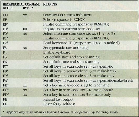
Table 4: Commands from the System to the 6805
At the lowest level accessible with programming, these commands control the
operation of the keyboard microprocessor. They are sent via OUT 60H,AL.
The 6805 responds to all transmissions by sending one or more bytes to the
output buffer of the 8042. The system can read each of these bytes by executing
an IN AL,60H. As with all communication involving the I/O buffers, a program
must determine that the input buffer is empty before sending a command to it
and that the output buffer is full before reading from it. Generally, the 6805
responds to a command within 20 ms. To the 8042, all data coming from the 6805
(whether scan codes or command responses) are equivalent. If scan-code
translation is enabled, any incoming data with a value that matches a scan code
are translated by the 8042. Therefore, in order to get correct command
responses from the 6805, a program should disable translation for the duration
of the communication.
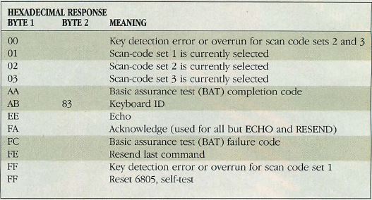
Table 5: Responses from the 6805 to the System
Besides sending the scan codes that corresponds to a user’s keystrokes, the
keyboard also sends the responses to system level commands (via OUT
60H,AL).
Responses from the 6805 are summarized in Table 5. Most often, the
response is ACK (acknowledge, FAH). For the two-byte commands, the 6805
responds to the initial byte with an ACK, stops scanning for keystrokes, and
waits for the second byte (the option byte). To the two invalid commands, the
6805 responds with Resend (FEH); to the Resend command it responds with the
previous output. Two commands (Read ID and Select Scan Code Set) produce
responses of multiple bytes.
The BIOS uses the Set/reset LED Status command whenever it detects a change
in the NumLock, CapsLock, or ScrollLock status. The low-order three bits of the
option byte control the status of the ScrollLock, NumLock, and CapsLock
indicators (bits 0, 1, and 2 respectively). Setting the bit turns the
corresponding indicator light on; clearing it turns the light off. There is no
means to read the current state to enable a program to set or clear just one
light without affecting the others.
The Set Typematic Delay command is used by the BIOS interrupt 16H function
AX = 0305H. The two parameters from registers BH and BL must be combined into
one byte by placing the repeat rate value into bits 0 through 4, and by placing
the initial delay value into bits 5 and 6. Bit 7 must be zero. The current
setting of the typematic parameters cannot be interrogated.
The Echo command can be used to determine whether or not an AT-compatible
keyboard is attached to the system. If, in reasonable time, the keyboard
responds with Echo (EEH), the AT—style keyboard is determined to be present.
Note that this response does not indicate whether or not an enhanced keyboard
is present, only that it is AT compatible. In practice, setting the typematic
rate and delay should work.
Only the enhanced keyboard supports the Read ID command; this command can be
used to distinguish between 84-key and 101-key models. Both keyboards respond
to this command with ACK, but the enhanced keyboard then follows this response
with two more bytes: ABH and 83H. A program that tests the keyboard type should
be written to time out if no further response is received within 500 ms of the
initial response. A valid response to this command indicates that the enhanced
keyboard is present, and that all of the commands in table 6 are valid.
This is the test used by the boot-up routine when setting the keyboard ID
bit in location 40:96H of the BIOS data area. The boot-up routine indicates an
enhanced keyboard if the second ID byte is either 83H or 85H. All of the
keyboards tested (from IBM, including the PS/2 models and several AT
compatibles) returned an ID of 85H.
Another feature present only in the enhanced keyboard is support for three
scan-code sets. The Select Scan Code command (followed by an option byte of 1,
2, or 3) activates the scan-code set of that number. An option byte of zero
causes the keyboard to respond with the number of the currently active
scan-code set. The code sets differ in the values generated for the press and
release of each key. (The Technical Reference Manual uses the terms make and
break for press and release.)
At boot-up, scan-code set 2 is activated by default. For most keys, it sends
a single-byte press code and a two-byte release code consisting of F0H followed
by the press code. These codes need to be translated to the ones expected by
the BIOS interrupt 09H routine. For example, the B key sends scan code 32H,
which, if passed to the BIOS, would be interpreted as M. With code translation
enabled, however, the 8042 keyboard controller translates the scan code to 30H
(the same as sent by the B key of the PC keyboard), which is properly
interpreted by the BIOS. The translation process also converts each two-byte
release code to a one-byte code that is the same as the press code with the
high bit turned on.
When scan—code set 1 is active, the keyboard produces codes that match the
result of translating scan—code set 2. For the keys common to the enhanced
and original PC keyboards, this code set produces the same press and release
codes as the original keyboard. In effect, this code set moves the translation
down a level from the 8042 to the 6805, therefore, scan-code translation at the
8042 level must be disabled.
Scan-code set 3 is similar to the default scan code in that it produces the
same scan codes for the majority of the ASCII keys and uses the same
press/release coding convention. The scan-code translation on the 8042 should
be enabled in order to use scan-code set 3. Some keys, though, are curiously
reassigned. For example, with scan-code set 3 activated and translation
enabled, CapsLock behaves like the left Ctrl key, the left Ctrl key functions
as the left Alt key, NumLock acts like Esc, the right Ctrl-key toggles the
CapsLock state, and so on. In fact, if the key caps were appropriately
relabeled, the keyboard layout would look very similar to the layout of the
84-key AT keyboard. A few unfortunate omissions must be noted, however. Except
for F1, the functions keys generate scan codes unknown to the BIOS; F1
generates the scan code for F12. The extended keys on the dedicated cursor
control keypad also generate scan codes that the BIOS cannot handle (so it
ignores them). Finally, no key generates the scan code for a backslash, and the
NumLock, CapsLock, and ScrollLock states cannot be turned off.
Scan-code set 3 has the rather unusual characteristic of allowing the
programming of keys to send scan codes only on press, only on release, or both,
and enabling or disabling the typematic repeating action. These characteristics
may be set for all keys at once, or for individual keys identified by scan
code. The support for this scan set is far from complete, therefore, using its
features would first require significant and time consuming programming
effort.
Sample Programs
Programmed routines that demonstrate most of the features of the new
keyboard are reproduced in Listing 2. Note
that this is not a complete program (although it will assemble with Microsoft
MASM 4.0) because it lacks a main program. The entire demonstration program,
KEYBINFO, is available in both source form and as a .COM file on PCTECHline.
This program can be run on any of the three IBM keyboards. It automatically
determines the keyboard type and displays appropriate data. On the enhanced AT
keyboard, starting KEYBINFO with an argument of 1, 2, or 3 switches the
keyboard to the corresponding scan code set.
[My God, that's spread over three pages...]
Listing 2: ATKEY.ASM
KEYBECHO.COM [KB ECHO] displays information
about individual keys: scan code, ASCII code, and key name (including any shift
states). It is very informative to run KEYBECHO after using KEYBINFO.COM [KB INFO] to change the scan-code set. The
source for KEYBECHO is in KEYBECHO.C and KEYBMISC.ASM; the object files from
compiling the first and assembling the second are to be linked together. This
source code is too large to be reproduced here. To ensure downloading of all
the necessary components, all source and executable modules have been archived
and placed on PCTECHline in the file named ATKEY.ARC.
The enhanced keyboard has many useful features, but its support at both the
BIOS level (scan-code set 3) and the operating system level (discarding
extended scan codes) is less than complete. Programming for it is tricky
because of incomplete documentation. Because IBM finally seems to have settled
on this keyboard model, however, it is worthwhile to search for solutions to
some of the problems.
Bob Smith is president of Qualitas, Inc, a software development firm in
Bethesda, Maryland. He is a member of the Capital PC User Group, Inc. in
Washington, DC.
|