|
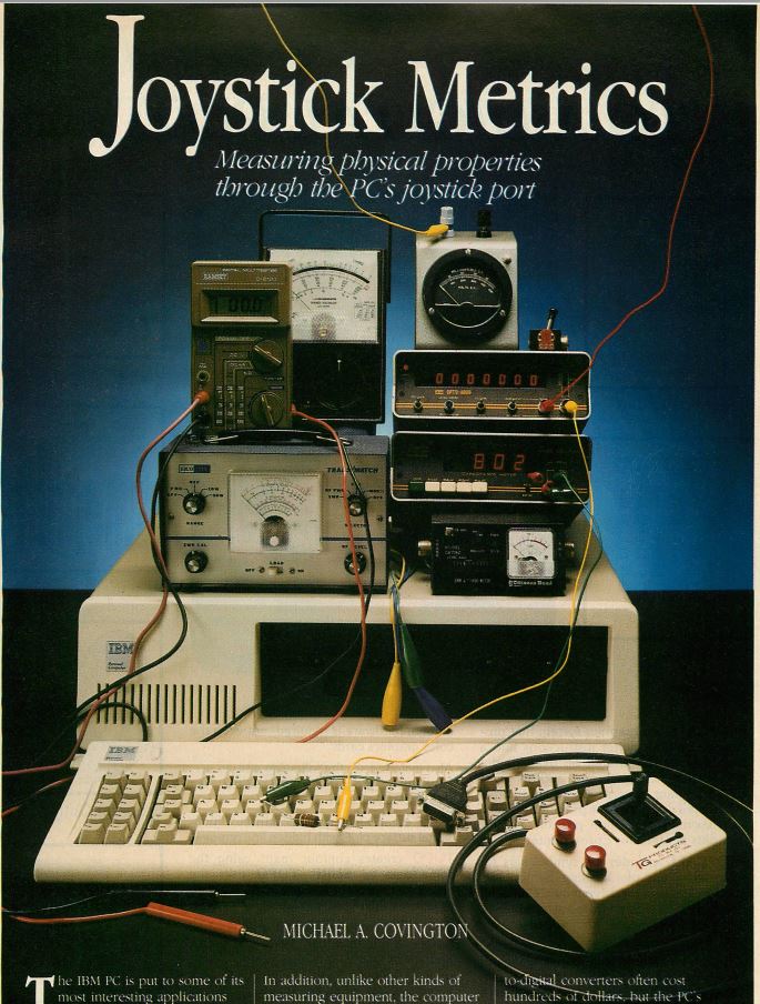
Author: Michael A. Covington
Source: PC Tech Journal, vol 3, No 5, May 1985, pages 99+
The IBM PC is put to some of its most interesting
applications when it is asked to handle data on and respond
to external physical conditions. Microcomputers can serve in
many such capacities: as superintelligent thermostat for
heating systems, data collection devices for the laboratory,
or automated troubleshooters for electronic equipment. In
addition, unlike other kinds of measuring equipment, the
computer can store and analyze large amounts of data
automatically.
Almost all of these applications require some form of
analog-to-digital conversion – that is, a continuously
varying quantity, such as a voltage, has to be converted
into a computer-readable form. Commercial analog-to-digital
converters often cost hundreds of dollars, but the PC’s
joystick port (officially called the IBM Game Control
Adapter) can be used to do the same job in a simpler way.
The circuits discussed in this article can convert the
joystick port into a device that will measure resistance,
capacitance, or voltage. No modification to the PC or the
adapter is required; the circuits all plug in externally in
place of the joystick.
These circuits have not been tested with the PCjr, but they
should be fully compatible with it. The PCjr BASIC and
Technical Reference manuals indicate that, with the
exception of the pin connections, the PCjr‘s built-in
joystick port is identical to the PC Game Control Adapter.
Performance with PC compatibles is hard to predict, but if
IBM’s Game Control Adapter card can be used in the computer,
chances are good for full compatibility in this area.
An IBM PC joystick consists of two potentiometers at right
angles to each other, plus two fire buttons; for simplicity,
only the potentiometers will be considered here. The
computer senses the position of the joystick by measuring
the resistance of each potentiometer, which varies from 0 to
100,000 ohms. This is done by timing how long it takes a
capacitor of known value to charge through the unknown
resistance.
FIGURE l: Joystick Port Circuit
(Simplified)
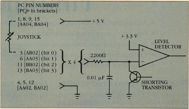
The joystick position is read by moving the short circuit
across the capacitor and measuring the time required for it
to charge to about 3.3 volts.
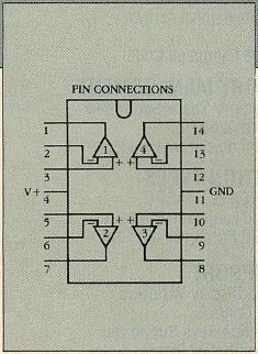
FIGURE 2: Joystick Port Pin
Connections
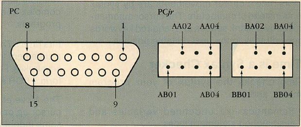
On the PC and PCjr, pins are numbered as seen by looking at
the joystick socket from outside the computer. On the PC,
pin numbers are usually shown on the connector. On the PCjr
(at right), AA0l and BA0l are the missing pins.
FIGURE 1 shows a simplified version of the circuitry inside
the joystick port; FIGURE 2 shows the pin connections. One
end of the resistance to be measured is connected to the
positive 5-volt supply; the other end is connected, through
a 2200-ohm resistor, to the capacitor. Normally, a switching
transistor keeps a short circuit across the capacitor to
prevent it from charging; the PC reads the joystick position
by removing the short circuit and timing how long it takes
the capacitor to charge to approximately 5.3 volts. The
result is a number between 0 and 255, roughly equal to the
resistance in Kilohms.
This result can be accessed in BASIC using the functions
STICK(0), STICK(1), STICK(2), and STICK(3), one for each of
the four potentiometers (there are two in each of the two
joysticks). When the value of STICK(0) is requested, the PC
reads the positions of all four potentiometers; when
STICK(1), STICK(2), or STICK(3) is requested, the results of
readings that were taken simultaneously with the most recent
call to STICK(0) are returned.
Listing 1: ANALOG BAS
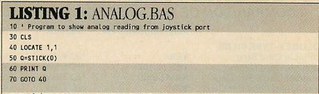
The program in LISTING 1 outputs a continuous display of the
value of STICK(0) that can be used while experimenting. Only
STICK(0) is used in this article, for the sake of
simplicity, but remember that the PC can accommodate four
copies of each circuit given here, all operating
simultaneously.
FIGURE 3: Measuring Resistance
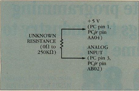
The unknown resistance need not be a joystick potentiometer;
it can be anything with a resistance in the appropriate
range. Because resistor and capacitor values inside the
joystick port vary among PCs, some preliminary calibration
is required.
Naturally, the unknown resistance need not be a joystick
potentiometer. It can be a resistor or anything else with a
resistance in the appropriate range (see FIGURE 3). To read
out the actual resistance in ohms, some calibration is
required, since the values of the resistors and capacitors
inside the joystick port can vary from one PC to another.
LISTING 2: OHM. BAS
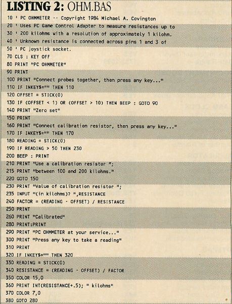
The program in LISTING 2 will perform the calibration. At
the beginning of each session, readings are taken of two
known resistances, one of which is 0 ohms (obtained by
shorting across the terminals where the unknown resistor
should go); the other should be a resistor with an
accurately known value between 100 and 200 kilohms.
FIGURE 4: Measuring Capacitance
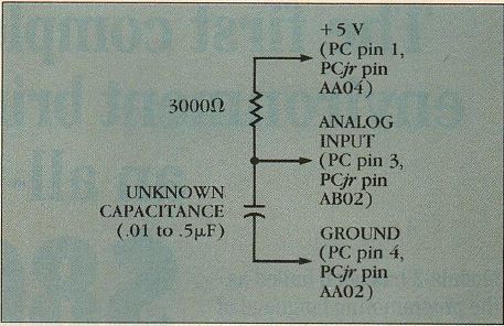
This circuit is slightly more complicated than that for
measuring resistance. Capacitance is measured by assessing
the time taken to charge the unknown capacitor in addition
to the
capacitor inside the PC. Two calibration values are needed.
The PC can also measure capacitance, but the circuit
required is slightly more complicated: it has two components
instead of one (FIGURE 4). The idea is to measure the time
taken to charge the unknown capacitor in addition to the
capacitor inside the PC, The requisite program is shown in
LISTING 3.
LISTING 3: CAPAC.BAS
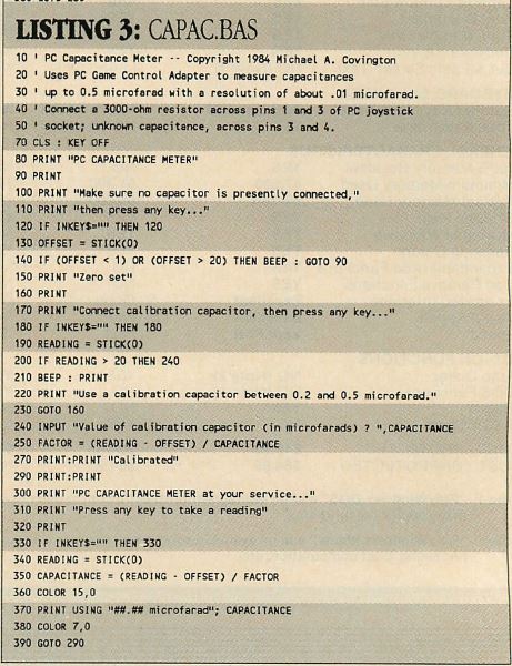
Again, two calibration values are required; one is 0,
obtained by leaving an open circuit in place of the unknown
capacitor, and one should be a capacitor with an accurately
known value between about 0.2 and 0.5 microfarads. The
program operates over a range of about 0.01 to 0.5
microfarads, with a resolution of about 0.01 microfarads.
To make the PC respond to light level, just substitute a
cadmium sulfide photocell for the resistor in the PC
ohmmeter circuit. Depending on the characteristics of the
photocell, calibration may turn out to be quite complicated.
There is probably no one program to suit all cases, but any
mathematical formula can be implemented easily on the PC.
FIGURE 5: A Simple Temperature
Sensor
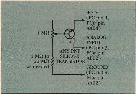
The same is true for measuring temperature, which can be
done in many different ways. A thermistor—a
temperature-sensitive resistor—can be used, but they are
often difficult to obtain. An easier alternative is to use a
silicon transistor (see FIGURE 5). All transistors are
temperature-sensitive to an extent and this sensitivity can
be exploited to take measurements.
The fixed resistor shown in the diagram should be chosen by
trial and error so that the value of STICK(0) comes out near
100 at room temperature. The potentiometer can then be used
for fine adjustment. In most control applications, the PC
will be used to detect that the temperature has reached a
certain level rather than to make quantitative measurements.
Note that the value of STICK(0) decreases with increasing
temperature. A resolution of 1-degree Centigrade or better
can be expected, depending on the type of transistor.
The most important kind of analog to digital conversion
involves voltage, since other analog quantities can be
converted into voltages relatively easily. To make the PC
measure voltage, it is necessary to convert the unknown
voltage into a constant or nearly constant current and use
this to charge the internal capacitor; the higher the
voltage, the shorter the charging time will be. The voltage
will then be proportional to the reciprocal of STICK(0),
rather than to STICK(0) itself, and resolution will be best
at lower voltages—which is as it should be, since small
voltage differences matter most when the total voltage is
small.
LISTING 4 is a program that can be used with any of the PC
voltmeter circuits given here. It requires calibration from
two known voltages, both in the range of the circuit used.
LISTING 4: VOLT.BAS
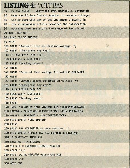
FIGURE 6: PC Voltmeter - Economy
Style
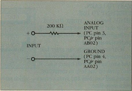
This circuit can be used only to measure voltages that are
high enough to charge the internal capacitor to the
threshold within the allowed time. The useful range is
between 5 and 18 volts. It is accurate to within .003 volts.
The simplest way to convert voltage to current is to run it
through a resistor; this is the method used in the circuit
in FIGURE 6. But this circuit can measure only voltages that
are high enough to charge the capacitor to the threshold
within the time allowed, which means that the circuits
useful range is about 5 to 18 volts. Within this range, it
is quite accurate. I assembled a test version and calibrated
it at 5 and 12 volts using VOLT.BAS; it was accurate to
within 0.03 volts for all values between.
FIGURE 7: PC Voltmeter - Deluxe
Style
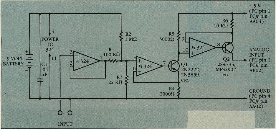
FIGURE 7 is the deluxe model PC voltmeter. Its useful range
covers 0 to about 6 volts; more importantly, no adjustments
are necessary—the software can do all calibration because
there is so little variation among units.
FIG 7a - Type 324 Quad Operational
Amplifier
The circuit, a voltage—controlled current source, uses a
type 324 quad Operational amplifier integrated circuit (op
amp IC). The output of the first stage is the same as the
input voltage. Resistors R1, R2, and R3 form a summing
network. A small, constant bias is added to the input
voltage so that 0 volts input will not give 0 output current
(if it did, the PC’s capacitor would not charge and it would
be impossible to take a reading). The second and third op
amps, the two transistors, and resistors R4, R5, and R6
constitute the current source itself. The voltages across
R4, R5, and R6 are held equal; the output current is equal
to this voltage divided by the value of R6.
The input and output voltages of the type 524 op amp can
swing down all the way to 0 volts, making a negative power
supply unnecessary. (For this reason, only the 524 or an
exact equivalent can be used in this circuit.) However, a
problem is posed by the upper limit of the 324‘s output
voltage, which is 1.5 volts below the positive supply. If
the 324 were powered from the 5—volt supply, its output
could not go above 5.5 volts, and the capacitor in the PC
would not charge within the time allowed. The solution is to
power the 324 (and obtain R2’s bias voltage) from a
higher-voltage power supply. In FIGURE 7, this is shown as a
9-volt battery, but any source of between 7.5 and 30 volts
DC will do; the current required is less than 1 mA If this
circuit is built on the prototyping area of the PC Game
Control Adapter Card, the PC‘s positive 12-volt supply can
be tapped.
FIGURE 8: Substitute For 9-Volt
Battery In Figure 7
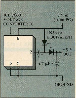
This circuit allows the voltmeter to be run from the 5-volt
power available at the joystick pins. The ICL 7660,
operating as an oscillator at about 8kHz, feeds a voltage
doubler and
outputs about 9 volts from the input.
FIGURE 8 shows a more subtle solution that enables the whole
circuit to run off the 5-volt power available at the
joystick port pins. An ICL 7660 voltage converter IC,
operating as an oscillator at about 8 kHz, feeds a voltage
doubler to give about 9 volts out from 5 volts in. The
output voltage is slightly higher if a type 1N54 or
equivalent germanium diodes are used, although silicon
signal diodes (1N9l4, 1N4148) are suitable.
The component values in the deluxe PC voltmeter are not
highly critical, but it is good to use 5—percent resistors
of the values specified. R4 and R5 should be well matched.
R6 controls the range of readings obtained; adjust it to get
STICK(0) to equal about 200 or 220 for 0 volts input, and
below 50 for the highest voltage to be measured. The
transistors can be any small signal silicon type (one NPN,
one PNP), preferably with gain (beta) above 50. The circuit
is designed to virtually cancel out variations in transistor
gain.
Used with VOLT.BAS, the deluxe model PC voltmeter performs
impressively. Using a breadboarded version of this circuit,
1 obtained 0.01-volt resolution for readings under 1 volt,
0.03-volt resolution up to 2 volts, and 0.1-volt resolution
up to 4 volts. After calibration at 0 and 5.2 volts, the
deluxe PC voltmeter agreed with my Micronta digital
multimeter to within 002 volts, resolution permitting, over
the entire 0-to-5-volt range—I am now not certain which of
the two is the more accurate!
One precaution: the input of the 324 sources a small current
that can be as high as 500 nanoamperes, though 20
nanoamperes is more typical. This can distort readings of
extremely high impedance voltage sources, such as the charge
on a capacitor. A 1-megaohm resistor across the input
greatly reduces this effect and makes possible readings
through a standard oscilloscope probe in either the 1:1 or
1:10 configuration. Alternatively, the input voltage range
can be extended with a voltage divider.
LISTING 5: OSCILL.BAS
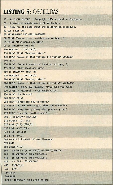
OSCILL.BAS (LISTING 5) plots a graph of voltage against
time, functioning like a chart recorder or slow,
single-sweep oscilloscope. The front end is exactly like the
PC voltmeter and can be used with any of the same circuits,
but the results are displayed as a graph of voltage against
time. A sweep takes about nine seconds and could be slowed
down by inserting delay loops. (The PC takes the same time
to evaluate STICK(0) whether the capacitor charges slowly or
quickly; if this were not so, the joystick would be more
responsive at one end of its range).
FIGURE 9a: PC Oscilloscope Circuit,
1Hz Square Wave
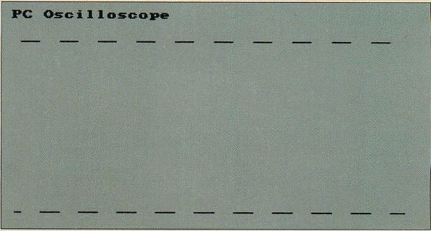
FIGURE 9b: PC Oscilloscope Circuit,
Capacitor Charging Curve
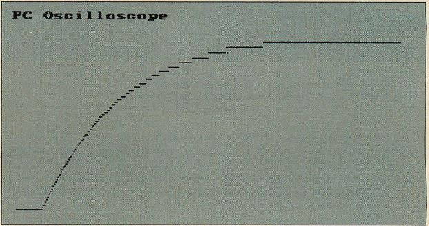
These figures display the output from OSCILL.BAS (LISTING 5)
taken with the
deluxe model PC voltmeter circuit, illustrated in FIGURE 7.
The top figure shows
a l-Hz square wave; the lower figure shows the charging
curve of a capacitor.
The drawings in FIGURE 9 show the PC oscilloscope‘s
interpretations of, respectively, a 1-Hz square wave and the
charging curve of a capacitor, taken with the deluxe model
PC voltmeter circuit. The bottom figure shows how the
resolution is highest at low voltages.
This PC oscilloscope program is only the beginning. With
proper programming, the PC can do far more than any ordinary
oscilloscope. It could generate logarithmic scales on one or
both axes, mathematically transform the data before
displaying it, automatically cut out long, monotonous
stretches from the waveform, store the readings, or even
plot calculated values against measured ones on the screen.
The PC costs little more than a good chart recorder and is a
lot more versatile. It can be the most powerful piece of
equipment in the laboratory.
Michael A Covington conducts research in artificial
intelligence and supercomputer applications at the
University of Georgia.
|