|
Introduction
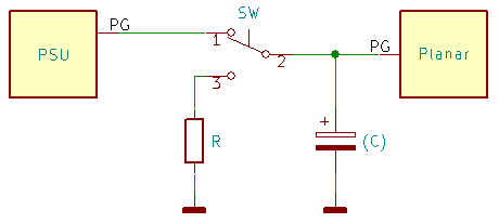
The Power Good Method
In-line Push Button
Push Button to Ground
Schmitt Trigger
Maintenance Service Header
Reset Button Bracket
Content by Tomáš "Major Tom" Slavotínek.
Introduction
One unfortunate thing about the PS/2 systems is that they lack a hardware
reset button of any kind. That can be rather annoying when experimenting with
different hardware and software configurations - if the system hangs and it
can't process interrupt requests from the keyboard, you won't be able to use
the Control+Alt+Delete combo to reboot the system. The only way out is to
power-cycle the entire unit, which isn't ideal. It's slow, as you have to wait
for the drives to spin down before you re-power the system. And if you have to
repeat this procedure over and over, it's not only a big waste of time, but
it's not exactly gentle to your hardware either...
Pretty much all personal computers can be modified with a hardware reset
button, even if they don't have a provision for one by default. You just have
to find a convenient spot for hooking into the reset circuit. That typically
isn't too difficult, but it may require some reverse engineering, component
level modification of the planar, or other actions that may be
beyond one's comfort zone or capabilities. Thankfully, there are also some less
invasive methods...
The Power Good Method (All PS/2s and other systems)
One approach that should work for all systems is to exploit the Power Good
(PG) line that goes from the PSU to the motherboard/planar. This signal is typically
wired directly to the reset circuit, and the PSU uses it to indicate to the
planar that all voltages are within the specified range and stable. If the
signal goes low (logic "0"), the system is put into a reset loop, because the
reliable operation of the computer can't be guaranteed under these conditions.
The system stays in this state until the Power Good signal returns to the high
state (logic "1"), at which point the CPU can start executing the POST code and
bring the system back up.
The Power Good signal is present on the power supply connector, and therefore
it's usually relatively easy to access it and modify its behavior to cover our
needs. All that without having to open the power supply or rework the planar
board, making it less risky (for both you and the computer) and easily
reversible.
Disclaimer: Even though this modification should be
perfectly safe when done correctly you should be particularly careful when doing any
PSU-related work and always double- or triple-check your work. The author is
in no way responsible for any damages that may occur as a result of your
actions. Proceed at your own risk!
There are many different ways of modifying the PG circuit - some are complex
but potentially more compatible and reliable. In some cases, you may need to
tweak the circuit (or parts values) to better work with a particular planar/PSU
combination, but the following text should give you enough information to get
it working.
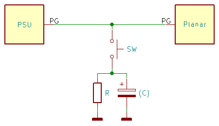
In-line Push Button
This method is based around a momentary push button with a normally-open
(NO) and normally-closed (NC) contact or contacts (either 3- or 4-pin). The
switch gets installed on the Power Good line with the NC contacts between the
PSU and the planar. The NO contact is tied to ground via a pull-down resistor
(100 - 1000 Ω). The entire pull-down part of the circuit may seem
redundant, but it's necessary because in most designs, the Power Good line is
floating on the planar side, and with the generating side (PSU) disconnected
(by the button), the signal may enter the "uncertain" region - preventing the
circuit from operating correctly.
An optional capacitor (0.1 - 1 µF) may be added between the Power
Good line and ground (on the planar side) to smooth out the switching a
little bit (debouncing). But many IBM planars already have a capacitor and a
gate with Schmitt-trigger inputs on the Power Good input, which makes it more
immune to noise.
The main downside of this method is that the switch must be installed
between the PSU and the planar. That makes it less suitable for systems where
the planar power connector is mounted directly inside the PSU shroud (Models
50/70, 95). On other machines, you can snip the Power Good wire in the
middle... if you don't mind doing so. Alternatively, you can create a cable
extension or unclip the contact from the connector and replace it with a piece
of wire terminated with a contact of the same style. Or, if you know what you
are doing, you can open the PSU and unsolder the wire on that end.
This circuit was tested on some non-IBM systems, but given its principle of
operation, it should work in all machines that use the classic active-high
Power Good signal.
Push Button to Ground
Unlike the method described above, this approach doesn't need a break in
the Power Good circuit. Instead, we will branch off the PG line and use a
normally-open (NO) momentary push button to tie it to ground through a
pull-down resistor.
Optionally we can add a parallel capacitor. This simple RC-circuit prevents
the system from entering a reset-loop (normally that isn't an issue,
but it's handy on systems with the DBA drive(s), as it prevents the drive(s)
from revving up).
 |
The problem with this method is that we are making assumptions about the PSU
circuitry responsible for generating the Power Good signal. We don't know what
the internal topology is or what the values of the used components are. These
implementation details can differ from one PSU model to another, making parts
selection for the reset circuitry more complicated. If the value of the added
pull-down resistor is too low, the drawn current may upset the PSU control
logic, trip one of the protections, and cause the unit to shut down. A value
too high may prevent the reset circuit from operating reliably or at all.
If you decide to add the parallel capacitor, the value selection becomes even
more precarious (avoid high capacitance values, as these can once again upset
the PSU). Determining the optimal values may require some reverse-engineering
or experimenting with different combinations.
This method was suggested by Frank de Jong (thanks!). It's based on
information from this thread,
and Frank successfully tested it on his Model 30-286.
Frank said (slightly edited):
The final working solution is as follows: wire the Power Good line
to a pushbutton and insert a 0.47 µF electrolytic capacitor shunted
by a 10 KΩ resistor between the pushbutton and Ground. The resistor
value does not matter much; I tested several resistors from 1K to 100K and
ended up using a 33K resistor. A higher value resistor will just drain the
capacitor more slowly. (Ed.: And at a certain point
the reset circuit would stop working altogether.)
Schmitt Trigger
Probably the most "kosher" way of implementing the reset circuit on the
Power Good line would be to use a logic gate with Schmitt trigger inputs. The
principle of operation is simple - use the gate (or gates) to realize a logic
"AND" operation on the original PG signal and a signal that goes low when the
reset button is pressed (pull-up to 5 V, button to GND, optional debouncing
capacitor). That should give you a very reliable and universally usable
circuit.
The obvious downside is the complexity of such a solution. You will have to
put the logic on a small PCB, supply it with 5 V from the PSU, break the PG line, etc.
This approach is currently untested, but there's no reason why it shouldn't
work since it's by far the most robust one and actually very close to how most
planars implement the Power Good/Reset logic. More information will follow if
I (or somebody else) decide to build and test the circuit.
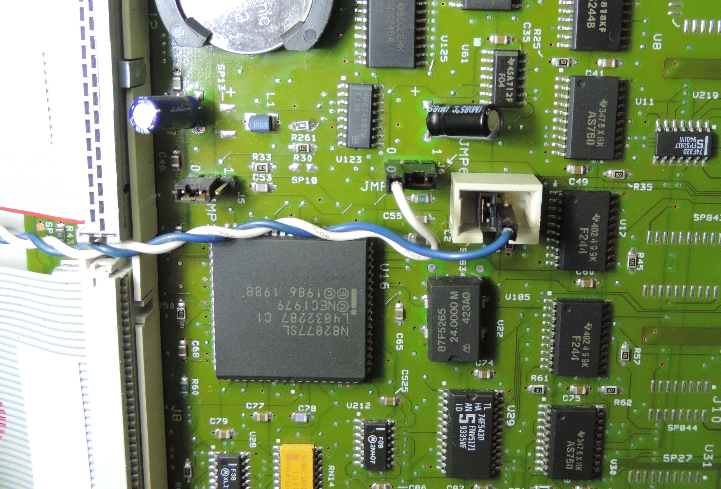
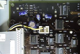
Maintenance Service Header (Late server systems only)
In case of the late PS/2 systems with the
JMP6 - Remote Maintenance Service
Connector things are significantly simpler because the JMP6 pin header
conveniently exposes the -RESET input. The "minus" prefix indicates that the
signal is "active low" - the "action" happens when it's tied to ground (logic
"0"). In this case, it means that if we connect pin 3 of JMP6 to ground, the
system will reset.
So, all we need is a regular button - ideally, one that already has a pair
of standalone pin header connectors attached (for example a power button from
any ATX case). Then just wire one end to pin 3 of JMP6 and the other to ground.
On the 9595A planar you can take ground
from pin 1 or 3 of the nearby
J103 - Remote Power-ON
header. On the 9585 K/N board, you
can use pin "0" of the JMP2 - PAP
header.
9595(A) Planar reset button wiring |

9585 K/N Planar reset button wiring |
When you have the button wired in and tested, it's time to find some
convenient place to put it. If you have the machine opened most of the time,
just hang it off the top side of the DASD cage, or put it to one of the 3.5"
bays where it can be accessed even with the side panel installed.
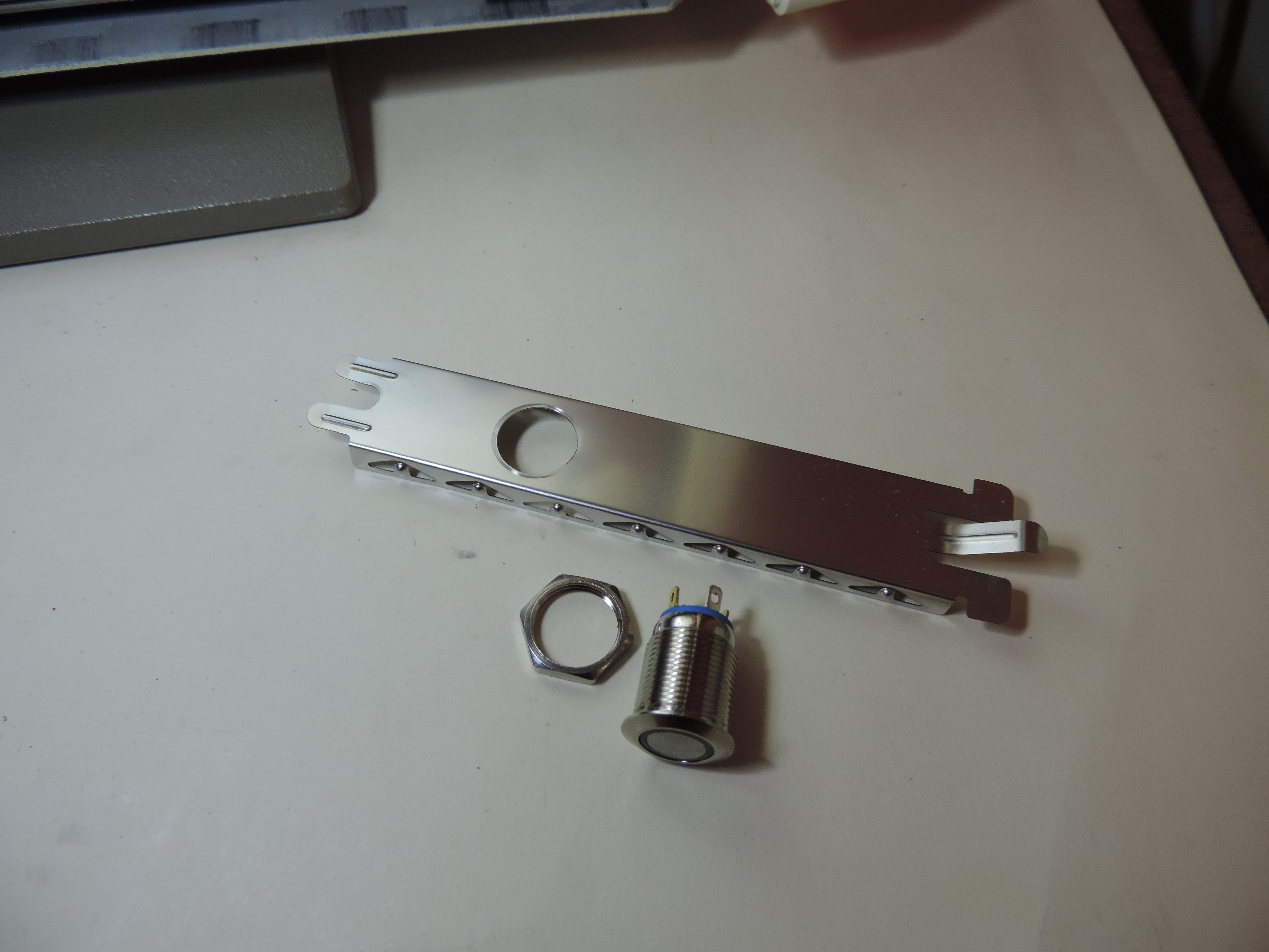
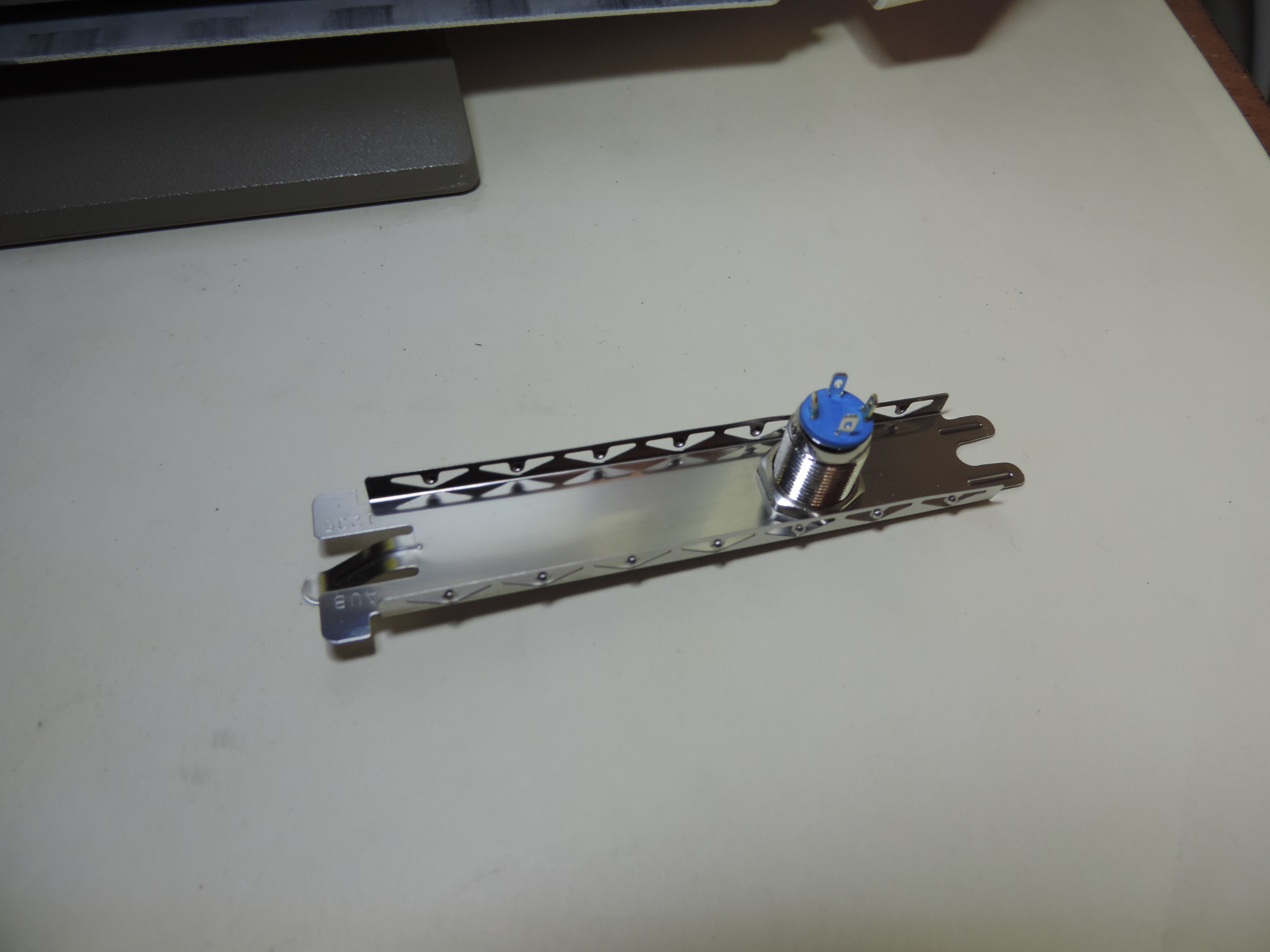
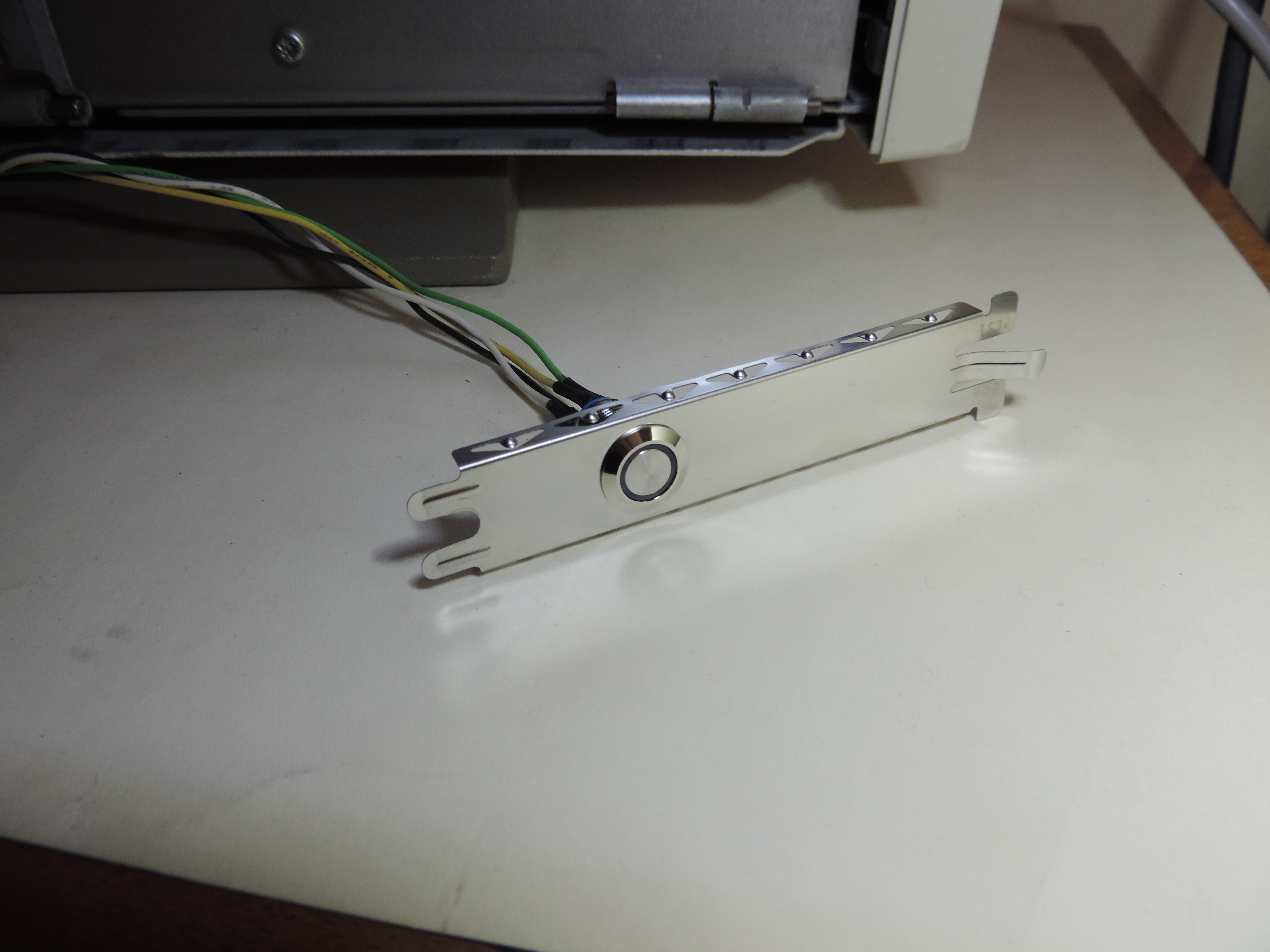
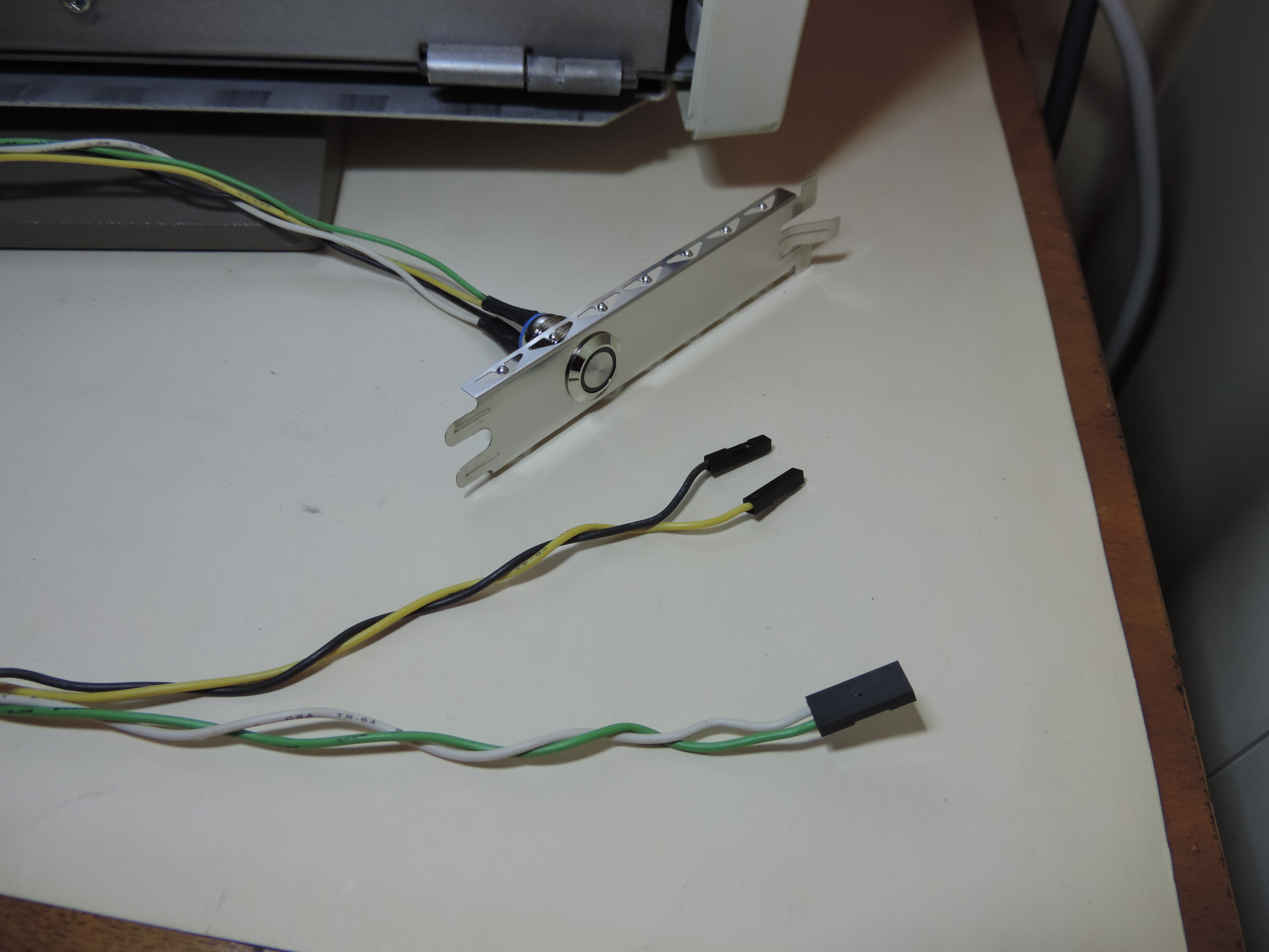
Reset Button Bracket
If you wish to use the switch even with the machine fully assembled, you
will have to do some minor modifications. Probably the easiest and least
invasive approach is to mount the switch to one of the MCA slot covers. The
covers are easy to remove, and you are not risking damage to any of the other
parts that may be more difficult to replace, should something go wrong. The
exact mounting method will differ depending on the switch type. I would
recommend a circular button that comes with a nut and a screw thread cut to its
body. All you need to install one of these is a hole of the appropriate
diameter...
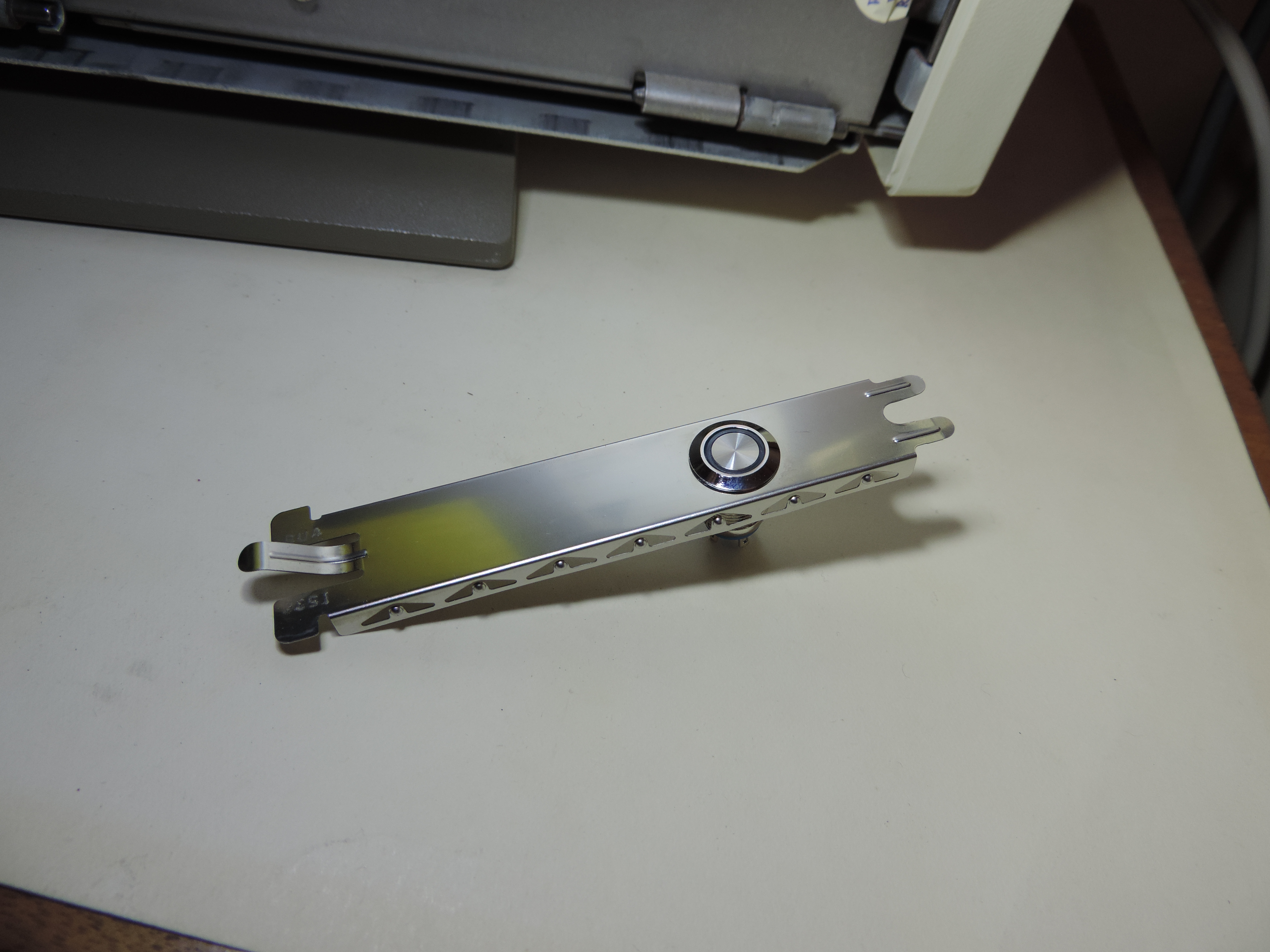
To avoid unintentional system resets it may be a good idea to use a flat
button that sits almost flush with the bracket and one that requires a slightly
higher push force to operate (see the pictures for an example).
If the switch you've used has exposed solder contacts like the one on the
photos, you should add some heat-shrink tubing or some other insulation over
the contacts.
You can ignore the extra two wires on the photos above, these just supply
power to the LED inside the button (it has no effect on the reset circuit
itself).
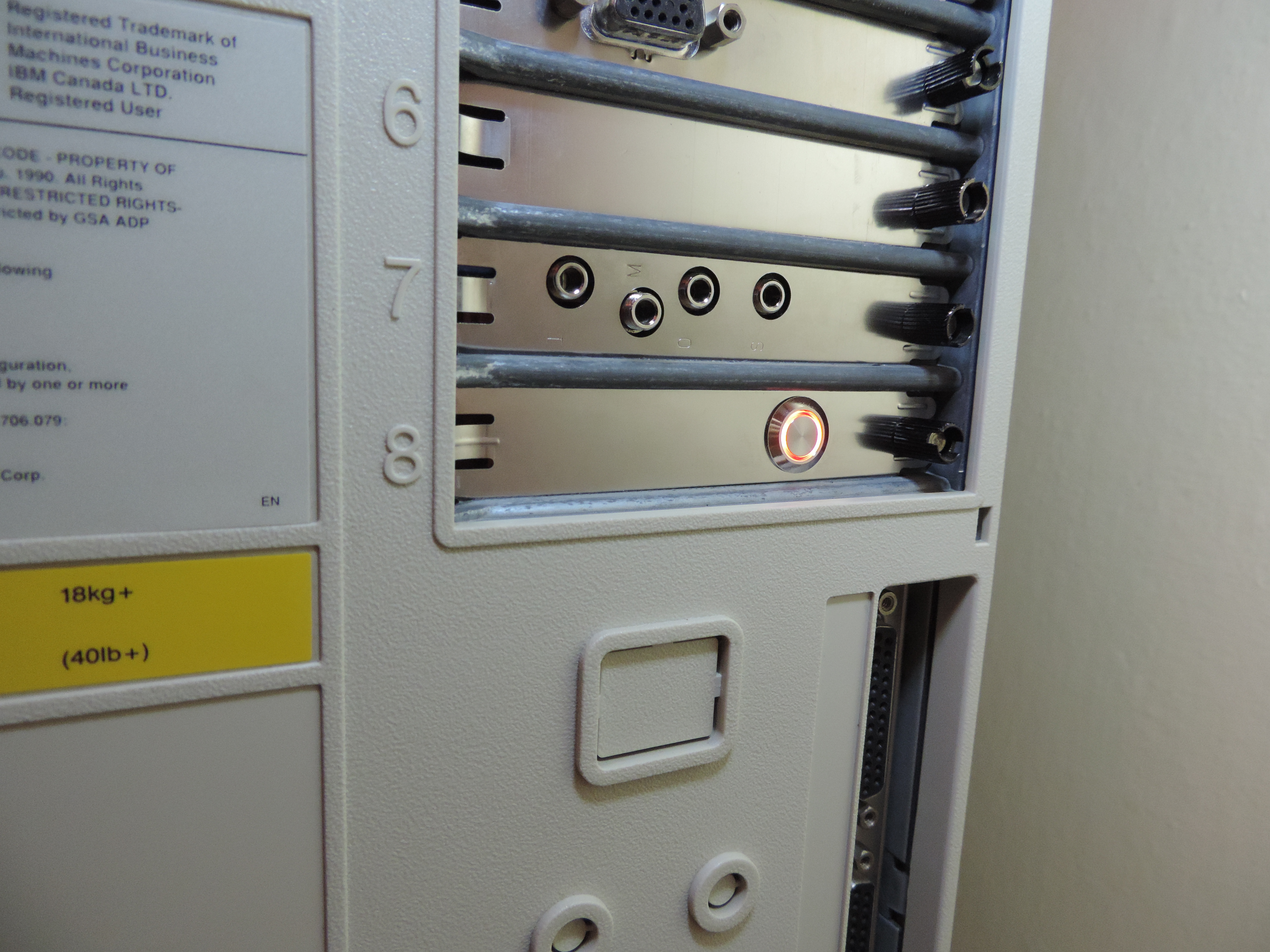
I've decided to use the bottom-most Slot 8 for the reset bracket, as it can
be easily located without looking. I usually don't install any adapters to
this slot anyway (makes it easier to remove the processor complex and it also
gives it some extra airflow).
|