|
@8F93.ADF IBM PS/2 ServerGuard
srvgrd10.exe IBM PS/2 ServerGuard Adapter Option v1.0
193-297 IBM PS/2 ServerGuard
194-184 IBM PS/2 ServerGuard (Re-announcement)
MASS/2 Monitor (remote monitor 8600 RMP or PS/2 ServerGuard. Win3.x, OS2, NW)
ServerGuard Front
ServerGuard Back
Power Planes Vcc, Vbb, and Vbat
ServerGuard Functions
PCMCIA Slot Use
ServerGuard under OS/2
Battery Pack
Construction
Power Control Box
Power Control Cable Pinout
Power Control Box LED Status Indicators
0275xx Series Errors
POST/Config Errors with SG Installed
False 027564 Errors
ADF Sections
ServerGuard Front P/N 61G3628,
FCC ID ANO70G7365
![[P]](/other/img/photo.gif "Front") (photo by Alexander Paterakis)
(photo by Alexander Paterakis)
The ServerGuard Adapter is a standard IBM Type-3 Micro Channel card size
(3.475" x 11.500").
The PCB has 10 layers (3 voltage, 1 ground, 6 signal planes).
BH3 Backup Battery, CR2032
C Catches for battery pack
CR1-CR3 LEDs
J1 Header for Remote Maintenance Port
J4 Power plug for 7.2v NiCad
J6 No idea
J7 No idea
J9 No idea
J10 No idea
J20 Power Control Cable Header
PCMCIA Slots Type II
Riser Header to PCMCIA slots
|
SP1 No idea
U1, U13 NS LM34
U2 CP Clare LQ54B00
U5 32.768 KHz osc
U6 Power Trends PT6101N
U7 NS LM2931 AT 5.0
U8 64F3777
U9 40.0000 MHz osc
U11 64F3776
U12 Sony CXK581001M-85LL
U100 Dallas DS1210S NVRAM controller
|
Note: Some field
failures have been isolated to the connector for the Power
Control Cable being inverted in its socket (J20) on the
ServerGuard Adapter. This is a keyed rectangular
connector, but it may be plugged inverted if forced. This
situation may damage either the power control module, the
Adapter, or both.
J6, J7 and J9, J10
Guessing big time here. Possibly both pairs
are headers to connect to a system power switch and the
System Board power connector on a 7546?
3 Volt Battery
The 3v CR2032 is used to maintain power to
the NVRAM and the real time clock. Average battery life
is estimated at 10 years.
Temperature Sensors
U1 and U13 provide input to the A-D
converter for monitoring the internal temperature of the
system. The two sensors are used to compute an average
temperature within the system.
The sensors increase the output 10mV per
degree F. The ADC represents each 10mV increment as one
bit value and measures a temperature range from -26F to
230F. (Ed. Boiling
water is only 212F!)
Jumpers
I see now why IBM is not an industry leader
now. To quote "The ServerGuard Adapter /A has two
jumpers: a password-override jumper and a manufacturing
jumper".
Password Override Jumper
[SP1?]
The Password-override jumper is used to
reset the administrative password in case the password
is forgotten or the NVRAM area becomes corrupted (if the
battery fails).
The administrative password protects
functions such as changing passwords, changing power
controls, setting error thresholds, and updating code in
flash memory.
When the jumper is on pins 2-3, it is in
the normal operating position. To override the admin
password, jumper pins 1-2. Restore the jumper to 2-3 to
protect the new password.
Ed. Now what the
hell? Which jumper is what?
PT6101N 1 A, 12-Pin
SIP Integrated Switching Regulator, +5 V datasheet
Power Indicator LEDs
When all LEDs are off, the adapter is in the sleep
mode.
CR1 When blinking
(about once every 5 sec) adapter is working
normally.
CR2 State of Vcc
power plane. When lit, the system power supply is
On.
CR3 State of Vbb
power plane. When lit, power input for the Vbb power
plane is present.
ServerGuard Back "DELIVERY BOYS"

U30 TI 406AAL (82G3495)
U38, U39 TI ADC0808FN CMOS
U40 Sony CXK581001M-85LL
U42 Sony CXK5864BM-70LL
U44 Not sure. Solder pads.
U45 Dallas DS1284Q Watchdog timekeeper
|
U49 06H3190
U51 71G0267
U52 06H2691
U58 32.0000 KHz or MHz?
U60 80C186XL20
|
U45 Time of Day Clock
The adapter uses a real-time clock with a
back-up battery as an alternate voltage source. This
clock is used to maintain an independent time-of-day
source, and it uses the alarm to schedule system power
events. Whenever the system power or battery pack (7.2v)
is off, the clock uses the back-up battery (3.0v)
U44 Mystery
Anyone with a component mounted on these solder
pads? See POST Errors
IBM PS/2 ServerGuard Features
| Flash Memory |
512KB |
| SRAM |
256KB |
| NVRAM |
8KB |
Power Planes
The ServerGuard has three separate power planes,
Vcc, Vbb, and Vbat.
Vcc Power Plane
This plane is powered by +5v dc from system
power supply and contains all system-interface logic on
the adapter. If the system is powered on, the adapter is
active.
Each time the system +5v goes below 2.5v,
an internal interrupt (AD_INT3) is generated to alert
the adapter microprocessor that power has been
removed.
Vbb Power Plane
This is powered from a voltage regulator
that receives it's input from the system +12v dc supply
when system is on. When system is powered down, the Vbb
Power Plane is powered from the 7.2v dc battery
pack.
It provides power for most of the
computational logic on adapter (microprocessor, memory,
and ADC). When the battery is the power source, Vbb
voltage can be turned off with the power-kill bit; this
bit has no effect when the system +12v is present.
When power to Vbb is removed, the adapter
is in sleep mode. The adapter is awakened by:
Incoming call to
the modem
Power-override
switch pressed on EPCB
Scheduled wake-up
alarm from RTC
Battery Voltage Plane (Vbat)
Powered from a voltage regulator, which
receives it's input from the system +12v supply when the
system is on or from the 7.2v battery pack when the
system is powered off. It contains the logic that
controls the power-on state of the system power supply
and the input for the Vbb power plane.
Logic on the Vbat plane is always active
and cannot be turned off, as long as the 7.2v battery
pack has power.
The functions on this power plane include
the Shutdown, Power-Kill, Suicide, and Low-Power Enable
registers, the LED and it's controls, the control logic
for the Vbb power plane, and the voltage regulator for
the Vbat power plane.
ServerGuard
Functions
Is it a PCMCIA Adapter?
No! Slot A
(upper) reserved for modem The modem is dedicated to
ServerGuard and is not accessible by computer software.
Slot B (lower) reserved
Modem Specs
It is a 2400bps, FDX modem with
auto-dialing, auto-answering, and sleep mode features.
In sleep mode, the modem responds to the ring-indicator
signal. When the modem is called, it generates an
interrupt to the adapter microprocessor.
Slot B Mystery
The tech ref never says Slot B is reserved.
It has the same programming information as Slot A. Maybe
the ADF can be hacked?
Supported Systems
The IBM PS/2 ServerGuard Adapter is supported in the
following systems:7546-411/640/641, 8580, 8590, 8595,
9577, 9585, 9590 and 9595
Operating System Requirements
OS/2.0 with CSD or OS/2 2.1 or
higher, NetFinity Manager for OS/2, NetFinity
ServerGuard Services and IBM PS/2 ServerGuard Mass/2
Monitor. NetWare support for the ServerGuard will be
available for Versions 3.11, 3.12 and 4.0.
Run from any System on Network
ServerGuard and NetFinity for OS/2's
features are available from the server system, or from
any PC on the network. Using IBM PS/2 ServerGuard
MASS/2 Monitor from a remote ASYNC system, the LAN
administrator can check and set alarm parameters,
display server temperature, server voltages, and power
condition. Additionally the LAN administrator can
power on/off or recycle power on the server.
MESSAGES, STATISTICS AND LOGS
Warning parameters for the system can be
set with the ServerGuard option. Once set, the system
automatically sends warning alerts to users, dials out
to remote pagers, or shuts down if operational limits
such as temperature or voltages reach unacceptable
limits.
ServerGuard
information is displayed graphically, and more detail is
available at the click of the mouse. The ServerGuard
option makes system operational statistics, such as CPU,
memory, and disk capacity utilization, available in real
time. NetFinity for OS/2 displays a record of the last
10 seconds to 10 days (user selectable) for each
statistic. The statistics can be stored to disk for
long-term storage and analyses.
ServerGuard records all critical
events in a non-volatile (NVRAM) log, easily accessed
for review. Because the ServerGuard is battery-backed,
the log can always be accessed even if the server is not
operating.
The ServerGuard allows reboot and power on/off control
of the server system.
LAN Access to configuration information
Server power control and system
reset capabilities controlled automatically or by
real-time commands
Alerts triggered by thresholds
that can be preset by the user
The ability to direct alerts to
pagers, LANs, remote or local systems
A battery backup designed to
allow communications with the ServerGuard card during
server power outages or when the administrator has
powered the server down
Levels of security and password
protection
Comprehensive error
logging
Remote (LAN) console/remote
ASYNC access capabilities
Remote (LAN) file transfer to
and from the server
Remote (LAN) entry of operating
system commands for execution
Compliance with emerging LAN
management standards and protocols
ServerGuard Functions
When the computer power goes down, the ServerGuard
Adapter:
Continues running
Time-stamps and logs the error
Dials out through modem, LAN, or
local server port to alert designated person of the
failure
Monitoring and Controlling
Resources
Internal computer temperature
Computer voltages (+5V dc, +12V dc, -12V dc )
Condition of the battery
Performance and errors for
-
Input and output devices
-
Operating system (for standalone computers )
-
Network operating system ( for computers on a network
)
Computer
power on and off
Sleep Mode
Must be such a thing. No idea right now.
Looks to be a power saving state.
Running ServerGuard under OS/2
For anybody who has one, here's what I did to
get it working in OS2. Download and install Netfinity 5.06
for OS/2 from IBM's site. Once that's running, download
OEP128A.EXE as well. Create the disk, then run the install
program. Change the source from c:\netfinity to a: and
choose the option to install for local administration and
then reboot. When you run Netfinity, you'll see the
ServerGuard option and from there you can look at the
logfile and set up settings for it. It works without the
power supply, but is limited of course. The power supply
for the IBM ISA remote management adapter is the same
thing and they can be found on ebay. External Power
Control Box
Battery Pack P/N 61G3629
A rechargeable 7.2v Ni-Cad
battery pack is used to power the adapter logic when the
system is powered off. The EPCB recharges the battery
while the adapter is in sleep mode.
When fully charged, it provides about 50
minutes of power to the adapter, or if the adapter is in
sleep mode, it provides about 60 hours of power. When
fully discharged, it takes about 24 hours to fully
recharge.
The adapter monitors the battery voltage, and
when the voltage reaches a predetermined threshold, it
takes the specified action (eg. go to sleep).
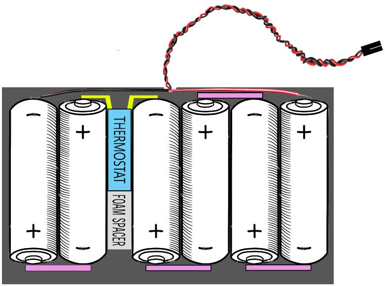
Battery
Pack Construction
Six AA sized NiCad cells, No special size needed.
7.2v, 600mAH total. Individual cells are marked "Japan
YA". To remove battery pack- squeeze both catches
inward. Pull the pack up , pivoting on the hinges that
are on the opposite side of the catches.
ServerGuard Battery Pack
Layout
From the artiste formerly known as Lorenzo
Mollicone
(New battery needs 24 hours to
charge)
6x Sony Cadnica N-600AAK [1.2v / 600mAh ]
Standard Charge 14-16 hrs at 60mA
Quick Charge 4-6 hrs at 180mA
Klixon 3-S
4MM70A-06 Datasheet
M3J
Battery Pack Plug: MX 20D [sounds Molex-ish]
Power Control Box P/N 71G6222 (used also with ASMA)
The External Power Control Box (EPCB) controls
the AC input into the system power supply. A cable
provides a control path from the ServerGuard to the
EPCB. The system power cord is plugged into the EPCB,
and the EPCB is plugged into an AC source. The
ServerGuard then controls the system power by signaling
the EPCB to turn power to the system on or off.
The EPCB has a power override switch.
When the switch is closed (on), AC power is provided to
the system regardless of the ServerGuard controls to the
EPCB. When the switch is open, the power to the system
is determined by signals from the ServerGuard.
The EPCB has two LEDs. The power-status
LED reflects the state of LED1 on the ServerGuard, and
the cable-attached LED shows if the control cable from
the ServerGuard is connected correctly.
Update: The revised ServerGuard has LEDs 3, 1, 2. LED 2
flashes with Power Status LED on the EPCB.
EPCB Connector
The cable from EPCB to adapter is a
shielded cable that connects digital ground on adapter
to digital ground on the EPCB board.
OVRIDE Pin 1
Override-status signal is an output to adapter that
indicates state of the power-override switch. A high
level indicates the switch is open, low indicates
closed.
EXTPWR Pin 2
External-power signal is an output to adapter and is
used to recharge 7.2v battery pack.
SHUTEN Pin 3
Shutdown-enable signal is an output to adapter and is
grounded in EPCB.
DCON Pin 4 This is
an input from adapter that is used with EPCB_CLK to
control power-up and power-down state of the system.
When SHUTEN is low, this signal is controlled by the
shutdown bit.
LEDON Pin 5 This
is an input from adapter that controls power-status LED
on the EPCB. It is controlled through Adapter Control
Register 1.
CARD_DETECT Pin 6
This is an output to adapter that indicates whether EPCB
is connected correctly. It is pulled low by EPCB. The
state of this signal is indicated in EPCB-status
bit.
GOOD_CABLE Pin 7
This is an input from adapter that controls the
cable-attached LED on the EPCB. It is lit when the
signal is low.
EPCB_CLK Pin 8
This is an input from adapter that clocks the data on
DCON. The data is transferred on the rising edge. It is
controlled by the EPCB Control register.
My
Power Cord was Bobbitted!
If someone sliced off your power cord, it uses an
8 pin mini-DIN plug to a 10 position header. Cable is
P/N 61G2145. It isn't a PS/2 plug, though it looks
like it without a center polarizing rib. Looks like a
Mac Local Talk plug...
Note: My 10 pin
header numbering is off. I do know that the "N" is
correct. N is pin 7.
EPCB
Pin |
Description |
10-pin
Header |
| 1 |
PWR OVERRIDE DETECT |
10 |
| 2 |
EXTPWR |
2 |
| 3 |
SHUTEN |
3 |
| 4 |
DCON |
4 |
| 5 |
LEDON |
5 |
| 6 |
CARD_DETECT |
6 |
| 7 |
GOOD_CABLE# |
8 |
| 8 |
EPCB_CLK |
9 |
| Shield |
Ground |
1 |
|
Open |
7 |
Power Control Box LED Indicator Status

| State |
Indicates |
Action |
| Power status LED |
| ON |
System on and functioning |
None |
| Blink |
SG is monitoring system |
None |
| OFF |
Power off too long / Battery failed. |
Charge battery. (POB, leave on 24hrs)
Replace battery pack. |
| Cable attached LED |
| ON |
Cable attached |
No action required |
| OFF |
Cable unplugged / bad, PCB unplugged. |
Attach / replace cable, Plug PCB in. |
PCB - Power Control Box
POB - Power On Button
0275xx Errors
The ServerGuard's series of error messages is HERE.
POST or configuration errors with ServerGuard installed
The ServerGuard Adapter causes 66
errors (configuration) during POST or isn't
recognized in Configuration. This exposure is limited to
POST.
Once the ServerGuard adapter has
successfully completed POST, it will function normally,
without further exposure to the problem until the system
is once again powered on (POST is run again).
Problem Isolation Aids Inspect the
ServerGuard card for a component (chip) at location U44.
If this module is missing, the adapter is NOT exposed to
this problem. The location of U44 is printed on the
card, but the lettering is very small. Refer to the
following diagram for the location of U44:
Backside of the ServerGuard
Adapter
Fix This problem is being corrected in current
production. A new version of the ServerGuard
adapter is available under FRU P/N 06H8091.
Ed. My SG doesn't
match the FRU or P/N. The two chips to the right of U44
(above) look to be EPROM, while my SG has flash. I do
have a U44 close to that location, but I will have to
install the SG to confirm my hunch.
View Configuration Symptoms
The chip (U44) caused numerous problems,
but the most obvious symptom is trashed configuration
and setup. Look at the MEMORY section of your VIEW
CONFIGURATION, are there musical notes instead of a
number? This is a giveaway to a bad ServerGuard
card.
Error
Code 027564 may be False
If error code 027564 is displayed (12 Volts
from power supply is bad) when running the ServerGuard
adapter diagnostics, but no system failures reported and
no other diagnostic failures are experienced, then it is
a false error. No hardware or software needs to be
replaced.
166 POST Error With
ServerGuard Adapter
During POST a 166 error is received indicating
the installed ServerGuard Adapter is "busy."
ALL PS/2 Servers with the ServerGuard adapter, FRU
P/N06H8091, installed may be affected.
Do not replace the ServerGuard Adapter.
This error may be caused by either inserting or removing
the modem from the PCMCIA socket, or connecting/
disconnecting the battery-pack to the adapter while
system power is on.
To Correct the Problem:
1. Power off system, remove ServerGuard adapter.
2. Make sure ServerGuard battery-pack is fully charged.
3. Disconnect battery-pack from ServerGuard for a few
seconds.
4. Reconnect battery-pack, make sure the 3 LEDs (CR 3,
1, 2) follow this sequence:
- CR3 comes on first.
- Seconds later, CR2 blinks 5x in 5 sec
interval, stays on for a few seconds and goes off.
- Seconds later, CR3 goes off.
- CR1 remains off the whole time.
AdapterID 08F93h IBM PS/2 ServerGuard
I/O Address Range
Unique I/O address range which is used to
communicate with this adapter
<8000-800F>,
8400-840F, 8800-880F, 8C00-8C0F, 9000-900F, 9400-940F,
9800-980F, 9C00-9C0F
DMA Arbitration Level
DMA channel used to transfer data.
<Arb 9>, 8, 7, 6,
5, 4, 3, 2, 1, 0, E,
D, C, B, A
Interrupt Level
Interrupt level for adapter. Ed.
IRQ 14 will give 95 the sh*ts...
<IRQ 5>,
IRQ 14
Fairness
On, adapter releases control of
bus as soon as another adapter preempts or requests
bus. Off, adapter holds bus until entire transfer
has been completed.
<On>,
Off
Adapter Serial Port Emulation
This is commented out. If
you want to enable this option, remove the ";" at the
front of each line. Serial port emulation makes this
adapter look like a SERIAL 1 port to the system. This
allows the modem port on this adapter to be used for
remote diagnostics in addition to the normal modem
functions that would be performed by this adapter.
When this function is enabled, SERIAL 1
should NOT be used as a general purpose serial
port. If remote diagnostics is not going to be
used, this function should be <Disabled>.
<SERIAL
1> IO 03F8h-03FFh Int 4,
Disabled
PCMCIA Slot A
This item is not
changeable. This adapter requires a Modem card inserted
into PCMCIA Slot A in order to operate. Do not remove
the Modem PCMCIA card in Slot A.
Modem card
PCMCIA Slot B
This
item is not supported at this time. Currently, this
adapter does not support the insertion of a PCMCIA card
into slot B. If the support becomes available in the
future, a flash update to the adapter's firmware
will be required and will be separately
purchasable.
Unavailable
|