|
Author: Dan Rollins
Source: PC Tech Journal, vol 6, no 4, April 1988 (pages 75-83)
Say goodbye to DIP switches and jumpers — POS has arrived. Programmable
option select, a feature of IBM’s Micro Channel architecture, configures
add—in boards entirely through software.
Since the first IBM PC hit the shelves, DIP switches and jumpers have been
the bane of PC professionals. With 16 switches on the system board and 16 or so
on the adapter, there are billions of ways to go wrong. For example, if two
serial adapters are both set to handle COM1, neither one will work. Any error
in the settings can cause one card to conflict with other cards, and the
problem can mean hours of poring over the documentation for the two
adapters.
Refinements in technology have made it practical to use programmable
registers to replace DIP switches and jumpers. In fact, when the difficulties
in documentation and the necessary end user support are considered, it is
probably cheaper to make the card programmable. On the PC/XT or PC/AT, a card
with program—selectable switches must contain additional hardware, such as an
EEPROM ‘or a battery-powered CMOS memory, to retain its settings.
With the introduction of the Personal System/2 models with the Micro Channel
architecture and the programmable option select (POS) feature, IBM has made all
of this switch-handling a thing of the past. Briefly stated, feature settings
on each Micro Channel card must be fully programmable. When a new card is
installed into a slot, users can be sure it will not interfere with other
cards. When a conflict exists (for example, two cards that are programmed to
use COM1), one card is disabled until the user can change its ”switches,"
which is done easily through a configuration program.
Furthermore, the card does not need to keep track of its own settings. The
configuration program saves the user’s “switch settings” in a bank of
battery-powered CMOS RAM on the PS/2 system board. The power-on sequence reads
these data and uses them to program each card. Up to 4 bytes— the equivalent
of 32 DIP switches—are sent to the card before any other access of the
card.
It is up to the card manufacturer to decide the meanings of the POS bytes,
but typical uses include the following: selecting the addresses of I/O ports;
changing the addresses of any on-board ROM; and setting interrupt levels (IRQ),
RAM addresses and options, direct memory access (DMA) arbitration type and
level, and DMA burst length. In short, any option that used to be set by DIP
switches and jumpers (in a painful session of manual labor) can now be selected
through software.
Power-On Sequence
The power—on sequence of the PS/2 is a superset of the sequence used in
the PC/XT/AT class of machines. When the 80286 processor powers up, it starts
executing instructions at absolute address FFFF0H. This address in the system
ROM contains a jump to the power-on self test (POST) procedure elsewhere in
ROM. First the POST thoroughly checks the CPU, interrupt controllers, and other
devices. Next, it checks the CMOS RAM. If the battery is determined to be bad
or the CMOS configuration data do not match the Cyclic redundancy check (CRC)
validity check value, the PS/2 assumes a minimum configuration.
If the CMOS memory passes the tests, the POS sequence begins. Starting at
slot 1, the POST program reads the ID of the adapter in that slot and compares
it with the first of the list of IDs in the CMOS RAM. If the ID matches, the
program switches the card into set-up mode, transfers up to four bytes from
CMOS to the POS ports, and reenables the card for normal operation. It then
moves to the next slot and continues until all adapters have been programmed.
If the ID read from a slot is different than the ID recorded for that slot in
CMOS, the system beeps twice, displays an error code on the screen, and writes
the error code to the CMOS for subsequent use.
Power—on processing continues with the familiar ROM—scan sequence.
Addresses between C800:0000H and D000:FFFFH are checked in increments of 2KB
for the ROM signature of AA55H. If the signature is found, the block of ROM
code is checked for a correct checksum and control is passed to the ROM to
allow the adapter to further configure itself. For example, in the case of a
hard disk adapter, further configuration might include hooking interrupt 15H
and sending a reset command to the controller. Next, the memory and I/O ports
are checked, and then the equipment list word that is returned by interrupt 11H
and the configuration record for interrupt 15H are set accordingly.
If no configuration errors were recorded in CMOS RAM, the POST attempts to
boot. The program first tries to boot from diskette drive A:—if unsuccessful,
it tries the hard disk; finally, if still unsuccessful, the POST displays a
diagram that prompts the user to insert a diskette and press F1.
If an error is found in CMOS RAM, the system will boot only if the reference
diskette is in drive A:. Otherwise, the system just stops and waits for the
user to press F1, without displaying any prompt other than the numeric error
code. If it finds the reference diskette, the system boots up into a program
that displays a screen that explains the possible causes of the error and gives
you the choice of running the configuration program.
The Configuration Utility
The Micro Channel hardware does not contain something that magically
prevents conflicts in addressing I/O ports, memory, or interrupt levels.
Instead, IBM created a clever piece of software, the System Configuration
utility (SC.EXE on the PS/2 reference diskette) and established a set of rules
that, if followed by card manufacturers and system integrators, can avert these
conflicts.
The SC utility performs the initial “setting of switches” on each
adapter, either automatically or in response to user input. It can detect and
prevent option conflicts because it operates on the adapters while they are
installed in the system; all settings on all boards are known. It also provides
a user~friendly face on rather complex activities, such as helping a naive user
select an IRQ or a DMA arbitration level. For users who have wrestled with the
AT’s primitive SETUP program, the PS/2’s SC is a real joy, offering pop-up
windows, menu—driven screens, and on—line help.
SC presents available options and provides help at each step. Any potential
conflicts are flagged, and clear instructions and explanations are provided. As
is explained later, the automatic configuration option resolves most conflicts
without the user having to make any decisions.
If IBM had tailored the SC utility for installing only IBM cards, the
company would have done a disservice to its users. Instead, IBM provided a well
defined, well-documented method for letting third—party card manufacturers
take advantage of the POS capabilities. Each adapter can have an adapter
description file (ADF). This is a text file containing information that SC
needs about the adapter, including its name, its adapter ID, all of its
programmable options—interrupts, I/O ports, ROM and RAM addressing, DMA
arbitration level—and the bit patterns that select each option.
The ADF has two purposes. First, it specifies a list of resource options;
the user (or the SC program, in autoconfigure mode) can choose options from the
list to avoid collisions with other adapters. Second, it provides a user
friendly interface for changing configuration options. Each ADF can contain as
much or as little hand—holding as required, including context-sensitive help
screens that are displayed when the user presses F1. For example, the ADF for
the IBM Multi—Protocol Communications Adapter contains more than 2KB of
information. After being processed with SC, however, this entire text file is
boiled down to four (or fewer) bytes of POS data that will be saved in CMOS
memory and sent to the card during power—on.
ADFs are named @xxxxADF; the W is replaced by the adapter ID‘s four
hexadecimal digits. The SC program reads and processes these files when it
finds an adapter with a corresponding ID number. The ADF text has a rigid
format, a sort of interpretive language understood by SC. This language
contains key words and string and numeric data elements. Tabs, spaces, and
new—line characters are treated as delimiters, except in quoted strings. ADFs
can be one long line or a set of lines, indented and easy to read. The ADF
example in Figure 1 illustrates the most important aspects of ADF syntax. This
ADF contains configuration data for the mythical Gizmo Adapter.
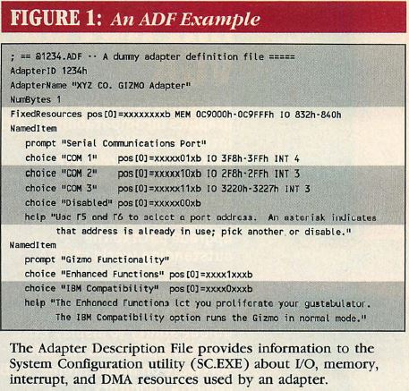
Figure 1: An ADF Example
Any line beginning with a semicolon, like the first one in the example, is a
comment and is ignored by the ADF interpreter. The second line contains the
required key word, AdapterID, followed by the four-digit adapter identifier.
Key words can be written in any combination of upper- and lowercase letters;
numeric values can be written in decimal or hexadecimal (hexadecimal values in
ADFs must include an H or h after the value itself).
The next line contains the key word, AdapterName, followed by a quoted
string of text. This text is informational only; SC displays it in the Change
Configuration window next to the slot number in which the adapter was found.
The NumBytes key word in the next line indicates how many bytes of POS data
will be sent during POS programming. The FixedResources key word specifies
those resources (addresses, I/O ports) whose locations cannot be changed.
Resource key words are 10, MEM, INT, and ARB.
IO specifies one or more ranges of I/O port addresses. MEM indicates one or
more ranges of memory addresses for either ROM or RAM. INT specifies one or
more hardware interrupts used by the card. ARB selects a DMA arbitration level.
DMA arbitration is a Micro Channel feature that helps hardware avoid DMA
overruns and collisions. The card does not need to support DMA arbitration, but
if it does, the configuration program should know so that it can ensure that
only one card uses a particular setting.
Each programmable feature of the adapter has a NamedItem section consisting
of a prompt that names the option and one or more choice values through which
the user can scroll by pressing F5 and F6 together. Each choice has a name (a
quote-enclosed string), a bitmap indicating the pattern of “switches” that
implement that choice, and a list of resources. As the user scrolls through the
choices, the SC program compares the resources used by each choice with those
for all other choices in the system; if any conflict exists, it displays an
asterisk (*).
The FixedResources section and each choice line require a pos key word that
specifies settings in one of the four configuration bytes (numbered pos [0]
through pos [5] ). Each POS byte can be thought of as a bank of eight DIP
switches. A 1 means turn that “switch” on, 0 means turn it off, and X means
leave it unchanged.
The first NamedItem in the listing has four choices: COM1, COM2, COM3, and
Disabled. Here, bits 1 and 2 of POS byte 0 select the I/O port used by the
adapter. Thus, each choice has a different setting for these two bits, and all
other bits are marked with Xs. Other options modify the other bits of this
byte; the result is cumulative.
Bit 0 of the pos [0] byte is always an X. Because this bit is used to enable
and disable a card, it cannot be used to select adapter features.
Finally, each NamedItem must have an associated help message. The help key
word is followed by a quoted string displayed when the user presses F1 while
the cursor is within the NamedItem. The SC program ignores carriage returns and
performs word wrap to make the message fit in the help window. If the message
is large, the arrow keys and PgDn and PgUp can be used to scroll through the
text.
To help nontechnical users, the SC program has an automatic configuration
mode that selects from the choices for each adapter without requiring any user
interaction. In this mode, SC scans the expansion slots in numeric order. For
each NamedItem, it attempts to pick the first choice; if that choice causes a
resource collision with a card in a lower-numbered slot, automatic
configuration tries each subsequent choice. If a nonconflicting choice is not
found, SC disables the adapter.
The automatic configuration algorithm is relatively simple; if it cannot
resolve a conflict, it does not attempt to backtrack and look for alternative
ways to configure other cards. For example, if slot 0 holds an adapter that has
a choice of I/O ports 3F8H or 2F8H (in that order), SC takes the first choice
and sets the adapter for I/O address 3F8H. If slot 1 holds an adapter that has
a fixed requirement for I/O port 3F8H, that adapter will be disabled, because
its resources are unavailable. SC does not go back to reconfigure slot 0 for
port 2F8H.
The result of automatic configuration depends on the order of choices in the
ADF and the order of the adapters in the slots. The conflict described above
would not occur if the ADF for the adapter in slot 0 listed the choices in
reverse order, or if the two adapters were switched so that the one with the
fixed resource requirements were configured first. Although users would not
ordinarily change the order of choices in an ADF, they could resolve many
conflicts simply by swapping the positions of the two cards. The most
configurable adapters should be placed in the higher-numbered slots. At the end
of configuration, whether manual or automatic, SC writes the selected choices
to the CMOS RAM, but not to the adapter. Then it reboots the system, and the
power-on sequence writes the configuration data to the adapter.
POS Details
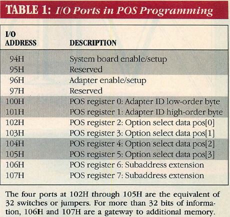
Table 1: I/O Ports in POS Programming
During the POS process, the POST routines communicate with the adapter by
means of the I/O ports listed in Table 1.
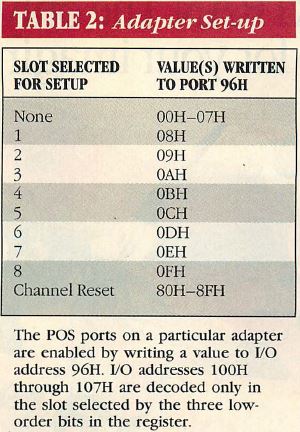
Table 2: Adapter Set-up
The program selects a slot by writing a value to port 96H as shown in Table
2. The slot number is encoded in three bits, meaning that the Micro Channel is
limited to eight expansion slots. Once the slot is selected, the program can
read the adapter’s identification number from ports 100H and 101H. To conform
to the Micro Channel standard, the adapter card must provide its identification
number in these ports when the card is selected via port 96H. To minimize
hardware on the adapters, the system board provides logic to set all undriven
bits of these ports to 1. The ID read from an empty slot has the value FFFFH.
Adapters need only supply logic to drive the 0 bits of the ID numbers Not
surprisingly, because IBM invented the game and sets the rules, it has reserved
for itself the high—numbered adapter IDs.
On each card, ports 102H—107H should contain the latches that are
programmed by the POS code. Port 102H receives the bit settings specified in
the ADF for pos [0], 103H the bits for pos[1] and so on. Note that the
numbering of POS ports Within the ADF differs from that used in the PS/2
Technical Reference (see Table 1), in which POS register 0 refers to port
100H.
The number and usage of the configuration bits are up to the manufacturer of
the adapter. Only one bit is actually required: bit 0 of the pos [0] byte (port
102H), which is a master enable switch. If this bit is set to 0, the card must
logically remove itself from the bus. When disabled, the card must remove any
RAM and ROM from the system address space; it must not raise any hardware
interrupts, perform DMA or other memory operations, nor respond to any I/O
activity (except for accepting POS programming). In other words, the card must
behave as if it were not installed. Thus, the Micro Channel integrity is a
cooperative effort; if a card manufacturer chooses to ignore the built-in
safeguards, it can easily cause the same problems that occur with PC/XT/AT
adapters.
Bits 6 and 7 of the pos [3] byte (port 105H) have a predefined significance,
but their use is optional. In a memory failure or other significant error, a
card may assert a signal that forces a nonmaskable interrupt (NMI). This was
also true on the PC and AT bus, but the computer could not tell which card
forced the NMI.
On the Micro Channel, the NMI handler can query each slot position and
examine bits 6 and 7 of port 105H. A card can use bits 6 and 7 to identify
itself as the source of the interrupt and to indicate whether or not additional
diagnostic information is available at ports 106H and 107H. Because the PS/2
Technical Reference does not document what the standard channel—check NMI
handler does, it is reasonable to assume that a card manufacturer must provide
a custom NMI handler, possibly in an on—board ROM.
The other POS data can be in any format. Just as each PC and AT card
manufacturer uses its own set of switches and jumpers, the bits of the bytes
sent to ports 102H—105H can be assigned to mean anything and can be programmed
in any order. If a card has few options, it can simply ignore any data sent to
unneeded ports.
Ports 106H and 107H, called the subaddress extension ports, provide a
means of writing more than four bytes of data to the adapter. The POS
programming that takes place during power up does not send data to these ports;
however, a software device driver or initialization code in ROM can use them to
communicate with an adapter. For example, the IBM PS/2 Memory Expansion Option
uses these ports to write up to 1,024 bytes of data into its translator RAM to
specify the starting address of each 16KB block of memory. Like the other POS
ports, 106H and 107H are decoded by a card only when its slot has been selected
for set-up via port 96H.
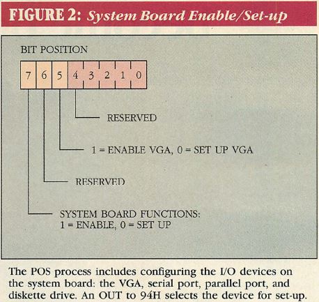
Figure 2: System Board Enable/Set-up
The PS/2 system board I/O devices can be programmed via the POS ports in a
similar manner. Instead of using port 96H to select a slot, an OUT to 94H
selects either the VGA or the other system board devices for POS set—up, as
shown in Figure 2. These devices are controlled by setting bits in port 102H
(see figure 2). Note that this port does double duty, programming either
adapters in expansion slots or devices on the system board, depending on the
bit settings in port 94H and 96H.
Each of the system-board devices (VGA, serial port, parallel port, diskette
drive controller) can be disabled, which allows their functions to be performed
by adapters in expansion slots. In addition, the serial port can be configured
as COM1 or COM2, and the parallel port can be configured as LPT1 through LPT3
and as either output—only or bidirectional.
POS Programming
The PS/2 Technical Reference sternly warns against setting POS
options outside the configuration program, threatening that damage to system
hardware may result. It further recommends that application software not
examine adapter ID numbers as a way to identify system hardware. The same
documentation then goes on to supply detailed instructions for doing both.
In reality, there is little reason to manipulate the POS settings. Once
configured, a card might not expect to be reconfigured (imagine flipping DIP
switches with the computer on). Of course, reprogramming RAM or ROM addresses
or changing I/O port usage without a subsequent reboot might result in an
unstable system. However, it might be desirable to reprogram an adapter on the
fly. A fault—tolerant system may have two identical adapters, one of which is
disabled. If the active adapter fails, it could be disabled and the backup
could be enabled.
POS programming of adapter cards
For programmers who might like to experiment with POS programming of
adapter cards, the steps for doing so are as follows:
- Disable interrupts (CLI).
- Do an OUT to port 96H, selecting the desired slot.
- Read the adapter ID from ports 100H and 101H.
- If this is the adapter of interest, place it into setup mode by writing a 0
to bit 0 of port 102H.
- Write POS data to ports 103H to 105H in any order.
- Write port 102H as the final POS byte. Bit 0 of this byte must be a 1 to
reenable the card.
- Turn off the set-up mode by writing a 0 to port 96H.
- Enable interrupts (STI).
Although the POS registers are sequential, making them candidates for 16-bit
I/O operations, the documentation warns specifically that they work with 8-bit
I/O only.
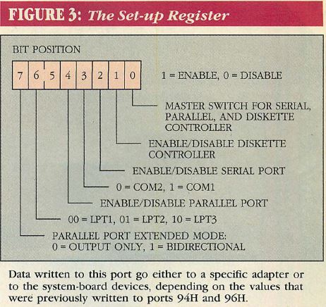
Figure 3: The Set-up Register
POS programming of system board
Programming the system board options is simpler than programming adapter
card options. The steps for doing so are listed below:
- Disable interrupts.
- Write to port 94H with bit 5 = 0 (VGA set-up) or bit 7 = 0 (other system
board device set—up). Set all other bits of the output byte to 1.
- Write one byte of data to port 102H to configure the devices as
specified in Figure 3.
- Turn off setup mode and reenable all system board features by sending
FFH to port 94H.
- Enable interrupts.
It is possible to read as well as write to the POS bytes for the system
board and all adapter cards. In programming the system board features, it is a
good practice to read the current state and then modify only those bits that
should be affected. To read the configuration of an adapter card, put the card
into set—up mode by sending its slot value to port 96H, then perform the IN
operations from ports 100H—107H, and get out of set—up mode by sending a 0
to port 96H.
Although IBM warns against reading card IDs indiscriminately, some
system-level programs must know which adapter is present to work correctly. For
example, an installable device driver may need to know if a certain adapter is
installed and if it has been configured in a specific way.
For an example of reading the POS ports, see Listing 1 (POS_READ.C). This
program checks each slot, looking for an IBM Multi-Protocol Communications
Adapter/A (with the adapter ID DEFFH). For each such card it finds, the program
then checks the POS bytes to see if the card is enabled for bisynchronous
communications and, if so, which ports it uses. Note that the programs main
loop checks all eight slots. On a four—slot Model 50, slots 5—8 appear the
same as empty slots, the adapter ID is FFFFH, and all POS bytes are read as
FFH.
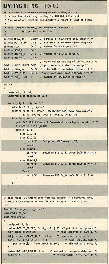
Listing 1: POS_READ.C
POS_READ.C simply displays messages about What it finds. A real
bisynchronous communications tool could use these data to make decisions; if
the adapter is not present or is configured improperly, the program could
abort, displaying instructions on how to configure the card correctly.
It is easy to see why IBM warns against card—specific activity. To obtain
usable information from the POS settings, the program must know the exact
meaning of each POS bit. A functionally equivalent card also could have a
different card ID or, even worse, a third-party card could have a particular ID
but a slightly different POS-byte bitmap (this has already happened with third
party Micro Channel memory cards). A program should test for functional
compatibility without relying on specific card IDs or POS settings.
CMOS Memory Usage
Like the AT’s system board, the PS/2’s board contains a battery-powered,
real time clock and 64 bytes of CMOS memory. This RT/CMOS memory contains
current time of day, hard-disk type, amount of memory on the system, and other
configuration data.
On the Models 60 and 80, an additional 2KB of CMOS memory holds the POS
set—up information. The data needed by the power—on POS activity consist of
6 bytes per slot—a 2—byte adapter ID and 4 bytes of configuration data.
These computers have eight slots, requiring a total of 48 bytes of POS data.
Layout of the extra CMOS space is not documented.
The Model 50, on the other hand, has only four slots, so it needs only 24
bytes of POS data for the slots. The AT—style 64-byte CMOS has just barely
enough reserved space to hold the POS data and the keyboard password without
causing any major rearrangement of other fields.
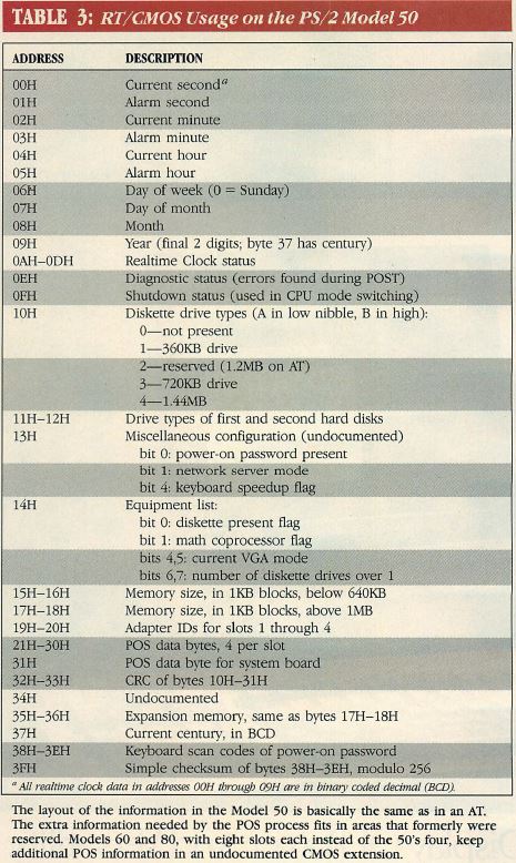
Table 3: RT/CMOS Usage on the PS/2 Model 50
Table 3 shows the layout for the CMOS RAM for the Model 50. The major
changes from the layout for the AT include those listed below:
- The diagnostics byte includes information that is specific to the PS/2,
including errors occurring during POS programming.
- A full byte identifies each hard disks drive type. The AT used one nibble
and a convoluted technique for recording disk types higher than 14. The PS/2
ROM BIOS supports 32 hard-disk types.
- The diskette drive—type field defines 720KB and 1.44MB drives.
- The hardware configuration record is extended to include 10H through 51H,
and the checksum validity check is replaced with a CRC. The CRC value is stored
at 32H and 33H.
- The 25 bytes between 19H and 31H are still marked in the documentation as
reserved, but they are part of the POS system for the PS/2 Model 50. The first
24 are the six bytes for each of the four slots. Address 31H contains the
configuration information for the system board.
- Addresses 38H—3FH contain the keyboard scan codes of the power-on
password. These addresses are peculiar, because they are always read as FFH,
having been ”locked” mysteriously during the POST. It is possible to
outsmart IBM and read the password by adding 40H to each address, that is,
reading from addresses 78H through 7FH. The moral is: Do not think of the
keyboard password as a high—security measure for preventing unauthorized
system access.
To read or write to the RT/CMOS, send the desired address to port 70H and do
an IN or OUT to port 71H. If any configuration bytes (10H—31H) are modified,
the invalid CRC will cause problems in the next boot-up, requiring the user to
run configuration utilities from the reference diskette.
If a program needs to modify the configuration record bytes, it must
calculate the CRC and place it in CMOS addresses 32H (high byte) and 33H (low
byte). A CRC is far more reliable than a simple checksum; compensating errors,
such as swapping the positions of two bytes, are flagged as errors. IBM’s CRC
generation technique is not documented, but was discovered after a little
investigation. A Turbo C version of the CRC generation routine used in the
configuration utilities is reproduced in listing 2 (CMOS.C).
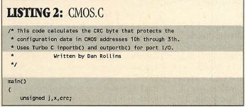
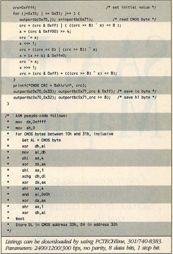
Listing 2 CMOS.C
An Appealing PS/2 Feature
Programmable option select is just one of many ingenious and convenient
features of the new PS/2 architecture, appealing to both the average user who
installs a new card once a year and the PC professional whose system unit is
laid bare more often than it is closed. For the former, it virtually eliminates
the process of finding and deciphering installation manuals; for the latter, it
saves time and ensures functionality. As users become more familiar with PS/2s,
using such features as POS, they undoubtedly will feel an increasing respect
and admiration for IBM’s work on these new machines.
Dan Rollins is a freelance technical writer. He is the author of the
"Help!” series, published by Flambeaux Software. His most recent work, the
Norton Online Guide to OS/2, was published in January 1988 by Peter Norton
Computing Inc.
|