|
Source: PC Magazine, 25 Jun 1991. Original HERE.
Author: Jeff Prosise
Converted to HTML by Louis Ohland. Edited by Major Tom.
BIOS stands for Basic Input/Output Subsystem. It gets this name
because it contains an extensive collection of input/output (I/O) routines,
which programs and operating systems can call upon to communicate with devices
attached to the PC. The name itself was probably borrowed from the CP/M
operating system, which contained a BIOS module in software that provided
machine-specific interfaces to the hardware the operating system was run on.
The BIOS on the PC is encoded in ROM. so you'll often hear it called the ROM
BIOS.
Physically, the BIOS is a chip or set of clips that Plugs into your
machine’s system board. Some adapters such us EGA and VGA video cards and
disk controllers contain their own BIOSes. which supplement the main BIOS. In
many cases, the routines stored in these adapter BIOSes replace routines in the
system board BIOS. The industry's two preeminent PC manufacturers, IBM and
Compaq. write their own BIOS code. Most smaller manufacturers depend on
compatible BIOSes from companies such as Phoenix. Award, and AMI. IBM published
the commented source code listings for the PC. XT. and AT BIOSes in the
technical reference manuals for those computers. If you can lay your hands on
one of these documents and aren't intimidated by long assembly language
listings, you can get a good idea of what BIOS code looks like and see how the
BIOS interfaces with individual devices.
Routines in the BIOS are accessed via software interrupts – CPU
instructions that pass control from the program currently executing to an
interrupt handler that lies elsewhere in memory. At start-up, the BIOS
initializes certain interrupt vectors in the PC's interrupt vector table (which
occupies the first 400h bytes of memory) to point to interrupt handlers within
itself. When DOS or an application program calls a interrupt, the interrupt
handler pointed to by that interrupt vector gets called. The interrupt handler
execute, a particular function selected by the AH register. This way, the
actual address of the routine is irrelevant: all the caller has to do is know
the function code and interrupt number for the service it wants to invoke.
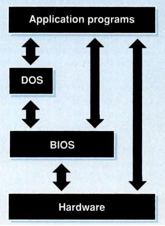
Figure 1: The Role of the BIOS. The BIOS offers a broad set
of I/O routines that programs and operating systems can use to interface with
the hardware they’re run on.
Figure 1 illustrates where the BIOS, acting as a low-level interface to the
hardware in a PC, fits into the system. DOS uses routines in the BIOS
exclusively to interact with devices such as the screen, keyboard, and printer.
For example, to throw a character up on the screen, DOS passes an ASCII code to
the CON device driver through interrupt 29h, also known as the Fast Console
Output Interrupt (see the February 12, 1991, Tutor column for an explanation).
CON in turn calls the BIOS Write Teletype function (interrupt 10h function 0Eh)
in the video BIOS to display the character. If ANSI.SYS has replaced CON, it
does the same thing but uses the BIOS Write Character and Attribute function
(interrupt 10h function 09h).
Similarly, the PRN device driver uses interrupt 17h, the entry point to the
BIOS printer I/O services, to output characters to the printer. And in one of
the very few instances when DOS uses the BIOS directly rather than using one of
its own device driven, it calls the BIOS Scroll Active Video Page Up function
to clear the screen when you type CLS (unless ANSI.SYS is loaded; in this case
it clears the screen by transmitting a clear screen escape sequence to
ANSI.SYS).
Application programs aren't nearly so well behaved. They're liable to use
services in the DOS kernel or BIOS or to program the hardware directly,
depending on which is the most convenient or the fastest. For direct device
I/O, most programs opt for BIOS services rather than DOS services, because the
former are generally more powerful and less susceptible to outside influences,
like presses of Ctrl-C or redirection operators. In some cases, even the BIOS
isn't enough. For example, most applications that use the serial ports program
the UART chips that drive the serial ports themselves, because neither DOS nor
the BIOS can support communications rates higher than about 1,200 bits per
second with the primitive serial port I/O functions built into them.
BIOS Services
Ignoring some of the less-common BIOS functions, the device I/O services the
BIOS provides fall into seven major categories:
- Video services (interrupt 10h)
- Disk services (interrupt 13h)
- Serial port services (interrupt 14h)
- System services (interrupt 15h)
- Keyboard services (interrupt 16h)
- Parallel printer service. (interrupt 17h)
- Time and date services (interrupt 1Ah)
|
| INTERRUPT 10H: VIDEO SERVICES |
| Fn. 00h | Set video mode |
| Fn. 01h | Set cursor type |
| Fn. 02h | Set cursor position |
| Fn. 03h | Read cursor position |
| Fn. 04h | Read light pen position |
| Fn. 05h | Select active video page |
| Fn. 06h | Scroll active video page up |
| Fn. 07h | Scroll active video page down |
| Fn. 08h | Read character and attribute |
| Fn. 09h | Write character and attribute |
| Fn. 0Ah | Write character only |
| Fn. 0Bh | Set color palette |
| Fn. 0Ch | Write dot (pixel) |
| Fn. 0Dh | Read dot (pixel) |
| Fn. 0Eh | Write teletype |
| Fn. 0Fh | Get video parameters |
| Fn. 10h | Set palette registers |
| Fn. 11h | Program character generator |
| Fn. 12h | Alternate select (misc. EGA(MCGANGA video services) |
| Fn. 13h | Write string |
|
| INTERRUPT 13H DISK SERVICES |
| Fn. 00h | Reset disk |
| Fn. 01h | Read status of last operation |
| Fn. 02h | Read sector or sectors |
| Fn. 03h | Write sector or sectors |
| Fn. 04h | Verity sector or sectors |
| Fn. 05h | Format track or cylinder |
| Fn. 06h | Format track or cylinder and set bad sector flags |
| Fn. 07h | Format disk |
| Fn. 08h | Read drive parameters |
| Fn. 09h | Initialize drive pair characteristics |
| Fn. 0Ch | Seek to track or cylinder |
| Fn. 0Dh | Reset disk (alternate) |
| Fn. 10h | Test for drive ready |
| Fn. 11h | Recalibrate drive |
| Fn. 15h | Get drive type |
| Fn. 19h | Park heads |
|
| INTERRUPT 14H: SERIAL PORT SERVICES |
| Fn. 00h | Initialize serial port |
| Fn. 01h | Transmit character |
| Fn. 02h | Receive character |
| Fn. 03h | Get serial port status |
| Fn. 04h | Initialize serial port (extended) |
| Fn. 05h | Get or set modern status register |
|
| INTERRUPT 15H: MISCELLANEOUS SYSTEM SERVICES |
| Fn. 00h | Turn cassette motor on |
| Fn. 01h | Turn cassette motor off |
| Fn. 02h | Read blocks from cassette |
| Fn. 03h | Write blocks to cassette |
| Fn. 4Fh | Intercept keyboard data |
| Fn. 85h | SysRq key pressed |
| Fn. 86h | Pause for specified length of time |
| Fn. 87h | Move a block of data from one location in memory to another in protected mode |
| Fn. 88h | Get size of extended memory |
| Fn. 89h | Switch CPU to protected mode |
| Fn. C0h | Get system configuration parameters |
| Fn. C1h | Get address of extended BIOS data area |
| Fn. C2h | PS/2 mouse interface |
| Fn. C3h | Enable or disable watchdog time-out |
| Fn. C4h | PS/2 Programmable Option Select interface |
|
| INTERRUPT 16H: KEYBOARD SERVICES |
| Fn. 00h | Read keyboard |
| Fn. 01h | Get keyboard buffer status |
| Fn. 02h | Get shift status |
| Fn. 03h | Set typematic and delay rates |
| Fn. 05h | Write character to keyboard buffer |
| Fn. 10h | Read Enhanced keyboard |
| Fn. 11h | Get Enhanced-keyboard buffer status |
| Fn. 12h | Get Enhanced-keyboard shift status |
|
| INTERRUPT 17H: PRINTER SERVICES |
| Fn. 00h | Print character |
| Fn. 01h | Initialize parallel port |
| Fn. 02h | Get parallel port status |
|
| INTERRUPT 1AH: TIME AND DATE SERVICES |
| Fn. 00h | Read system timer |
| Fn. 01h | Set system timer |
| Fn. 02h | Read time |
| Fn. 03h | Set time |
| Fn. 04h | Read date |
| Fn. 05h | Set date |
| Fn. 06h | Set alarm |
| Fn. 07h | Reset alarm |
|
|
|
Figure 2: Summary of BIOS Services. Routines in the BIOS are
accessed via software interrupts - CPU instructions that pass control from the
program currently executing to an interrupt hander.
|
These services are summarized by interrupt and function number in Figure 2.
Not all the BIOS services are shown. I've omitted some that are rarely used or
that appeared only in PCs that are now defunct (for example. the PCjr). Also,
not all the services listed are available on all PCs. Whether or not a function
is supported by the BIOS depends on several factors, including the type of PC,
the hardware that's installed, the brand of BIOS you're using, and the date it
was written. It's not unusual for programs to restrict themselves to a narrow
range of BIOS calls so that they can run without modification on a wider
variety of machines. For example, not many programs call on the video BIOS's
Write String function, even though it's a very convenient one to use. This
function isn't implemented on video adapter, predating the EGA, so using it
modem a program incompatible with systems equipped with CGA and MDA video
cards.
The list in Figure 2 will give you some idea of the breadth of services the
BIOS offers. Unfortunately, it’s not possible to examine them all in the
space we have here. For additional information on these services, there are
many references available at local bookstores, including Ray Duncan's Advanced
MS-DOS, from Microsoft Press. You may also order IBM's official reference to
BIOS services, the Personal System/2 and Personal Computer BIOS Interface
Technical Reference (part number 68X2341), by calling 800-IBM-PCTB. The cost is
(ouch!) $150. A supplement (part number 15F2161) is available for an additional
$18.
More than I/O
In addition to these low-level hardware interface routines, the BIOS
contains the code for the Power-On Self Test, or POST, and the bootstrap
loader. The POST is the cries of diagnostic routines, executed when you turn
your PC on, that ensure the hardware components of the system are working
properly. The POST was discussed in the February 19, 1990, Tutor Column. The
bootstrap loader is the routine that reads the boot sector from a DOS disk and
transfers control to the boot sector's code that loads (bootstraps) the
operating system into memory.
The BIOS also contains handlers for selected hardware interrupts. For
example, every time channel 0 of the PCs system board timer produces a clock
pulse (it does so approximately 18 times every second), a hardware interrupt is
generated that activates a BIOS interrupt handler. The interrupt handler
updates the system's software clock and performs other housekeeping chores.
Another example: When a key is pressed or released, the BIOS fields the
interrupt generated by the keyboard controller and reads a scan code from the
keyboard. After converting the scan code into the equivalent ASCII code based
on any other keys depressed at the same time (for example, Ctrl, Alt, or Shift)
and the current states of NumLock and CapsLock, the interrupt handler stuffs
the key code into the keyboard buffer. The BIOS also houses the code that dumps
a screen to the printer when the Print Screen key is pressed.
Another element that mustn't he excluded from a survey of the BIOS is the
PC's Hard Disk Parameter Table. This ROM-based table defines the
characteristics (for example, the number of heads, sectors, and cylinders) of
all the different hard disks that can be installed in the PC. Generally, adding
a hard disk whose properties do not appear in this table requires that you
purchase a BIOS upgrade or install a third parry support utility such as
Ontrack's Disk Manager.
The BIOS Data Area
|
| SERIAL PARALLEL PORT DATA AREA |
| 400h | 4 words | Base I/O address for COM1 through COM4 |
| 408h | 4 words | Base I/O address for LPT1 through LPT4 |
|
| MISCELLANEOUS DATA AREA |
| 410h | Word | Equipment flags |
| 413h | Word | Memory size in kilobytes |
|
| KEYBOARD DATA AREA 1 |
| 417h | Byte | Keyboard shift state flags 1 |
| 418h | Byte | Keyboard shift state flags 2 |
| 419h | Byte | Alternate keypad entry |
| 41Ah | Word | Address of keyboard buffer head |
| 41Ch | Word | Address of keyboard buffer tail |
| 41Eh | 32 bytes | Keyboard buffer |
|
| FLOPPY DISK DRIVE DATA AREA |
| 43Eh | Byte | Recalibrate status |
| 43Fh | Byte | Motor status |
| 440h | Byte | Motor off counter |
| 441h | Byte | Status of last operation |
| 442h | 7 bytes | Controller status bytes |
|
| VIDEO DATA AREA 1 |
| 449h | Byte | Current video mode |
| 44Ah | Word | Number of columns of text displayed |
| 44Ch | Word | Length of regen buffer in bytes |
| 44Eh | Word | Offset address of active display page |
| 450h | 8 words | Cursor position (video page 0-7) |
| 460h | Word | Cursor type (beginning and ending scan lines) |
| 462h | Byte | Active video page |
|
| VIDEO DATA AREA 1 (cont.) |
| 463h | Word | CRT controller base address |
| 465h | Byte | Current setting of 3x8 register |
| 466h | Byte | Current setting of 3x9 register |
|
| SYSTEM TIMER DATA AREA |
| 46Ch | Word | Low word of timer count |
| 46Eh | Word | High word of timer count |
| 470h | Byte | Timer rollover indicator |
|
| SYSTEM DATA AREA 2 |
| 471h | Byte | Break-key state |
| 472h | Word | Reset flag |
|
| HARD DISK DATA AREA |
| 474h | Byte | Status of last operation |
| 475h | Byte | Number of hard disks attached |
|
| TIME-OUT VALUES |
| 478h | 4 bytes | Time-out value for LPT1 through LPT4 |
| 47Ch | 4 bytes | Time-out value for COM1 through COM4 |
|
| KEYBOARD DATA AREA 2 |
| 480h | Word | Address of start of keyboard buffer |
| 482h | Word | Address of end of keyboard buffer |
|
| VIDEO DATA AREA 2 |
| 484h | Byte | Number of rows of text displayed minus 1 |
| 485h | Word | Height of character in scan lines |
| 487h | Byte | Miscellaneous video information |
| 488h | Byte | Miscellaneous video information |
|
|
|
Figure 3: The BIOS Data Area. The BIOS Data Area comprises
a 256K area of RAM stretching from absolute address 400h to 4FFh.
|
The 256-byte region of RAM that immediately follows the Interrupt Vector
Table and stretches from absolute address 400h to 4FFh is set aside for use by
routines in the BIOS. This area is called the BIOS Data Area. Figure 3 lists
some of the information the BIOS places there. Programs can inspect memory
locations in this region and obtain valuable information about the state of the
system. From the byte at 484h, for example, a program can determine how many
lines of text are currently displayed on a system equipped with an EGA, VGA, or
XGA video adapter.
Sometimes it's useful to manipulate data in this region. You can clear the
keyboard buffer by reading the word value at 41Ah and poking it into address
41Ch. These locations hold the head and tail addresses of the keyboard buffer,
so setting them equal to each other tricks the BIOS into thinking that there
are no more key codes awaiting processing.
PS/2s set up an additional data area in RAM for the BIOS's use, called the
Extended BIOS Data Area. At start-up, the PS/2 POST determines how much
conventional memory is installed and cordons, off an area at the very top for
the BIOS to use as a scratch pad. The size of this area is normally 1K.
However, the designers of the PS/2 made provisions for more. The address of the
Extended BIOS Data Area is obtained by placing a call to interrupt 15h function
C1h. The first byte in the data area reveals the size of the area in kilobytes,
so theoretically, up to 255K could be reserved this way. The PS/2 hides the RAM
it sets aside for the BIOS in such a way that the rest of the system doesn't
even know the RAM is installed.
The ABIOS
The Extended BIOS Data Area wasn't the only wrinkle that PS/2s introduced to
the BIOS. Most PS/2s actually contain two BIOSes: the CBIOS, a superset of the
original IBM BIOS (the C stands for Compatibility), and the ABIOS, or Advanced
BIOS, which supports multitasking operating systems such as OS/2. The ABIOS is
the protected-made analog to the CBIOS. When OS/2 is run on an AT-class
machine, it bypasses the BIOS and interacts with the hardware directly. On a
PS/2, however, it relies on functions in the ABIOS. In this respect, the ABIOS
(when it is present) plays exactly the same role in a system running OS/2 that
a conventional BIOS does in a system running DOS.
In the first IBM PC, the BIOS was a mere 8K in length: the PS/2 BIOS now
stands at 128K. With this kind of growth, who knows what the nest ten years of
BIOS development will bring!
|