|
Author: Pat Moran
Source: Australian Personal Computer, Vol 9, No 5, May 1988 (pages 21-33 physical)
The method of power sharing provided by IBM's Micro Channel Architecture is
not limited to OS/2 systems: many PCs can benefit from this CPU bypass
operation. Pat Moran explains how.
In April, 1987, IBM announced a new series of personal computers — the
PS/2 range. At the heart of this range was a new hardware architecture, the
Micro Channel (MCA), which linked the central processor, memory and peripherals
of the PC in an intelligent rather than a passive manner.
At the same time, IBM and Microsoft jointly announced a new multi-tasking
operating system, OS/2. Immediately, speculation arose that OS/2 would only run
on machines which were based around the MCA. IBM did little to dispel this
myth, although Microsoft has continued to claim, and manufacturers other than
IBM have demonstrated that OS/2 will run on most existing 80286 and 80386-based
PCs without the MCA.
Nonetheless, the Micro Channel is more than a new bus slot design for add-in
cards and a pretty set of tracks on the motherboard. It is in fact a powerful,
intelligent method of sharing processing control between devices on the PC's
bus. This power sharing can be used to improve the performance of multi-tasking
operating systems such as OS/2 or Unix by bypassing the bottleneck of the
CPU.
What is the Micro Channel?
The Micro Channel is a combination of several buses (address bus, data bus,
transfer control bus, arbitration bus) and multiple support signals. The
channel architecture uses asynchronous protocols for control and data transfer
and provides several new features. These include:
- level-sensitive interrupts;
- arbitration between devices with different priorities;
- multiple masters; and a
- programmable option select.
The programmable option select (POS) was introduced to simplify the
installation of adapter cards in a PS/2 by eliminating switches and enabling
card clashes to be detected automatically and resolved where possible. When
clashes cannot be resolved, one of the adapter cards is automatically disabled
to enable the system to continue to function.
Although the POS is directly of interest to the end user, the other new
features are of much greater interest to system designers and programmers who
are considering how to exploit the new systems.
This article, therefore, concentrates on the aspects of the Micro Channel
Architecture (MCA) which need to be understood in order to exploit its
versatility, reliability and performance features. The MCA incorporates many
features aimed at improving the reliability of the system, and at least
detecting — if not automatically recovering from — transient or
non-transient error conditions.
Multi Device Arbitration Interface
The Multi Device Arbitration Interface has been designed to support both
Direct Memory Access (DMA) features and multiple masters, and to prioritize
their access to the channel while providing burst capability with fairness and
preemption features.
The aim of a DMA controller is to reduce the cost to the system processor of
handling a peripheral. Without a DMA controller, the central processor has to
be interrupted each time a byte is to be transferred to or from a device. Such
an interrupt can be expensive since the processor has to save the registers and
its state before servicing the device, and then it has to restore its state so
that its interrupted activity can be resumed. The device is serviced either by
reading data from the device and storing it in a buffer, or obtaining it from a
buffer and sending it to the device. Consequently, the processor also has to
maintain a count of the number of bytes transferred and update the buffer
pointers as each byte is transferred.
A DMA controller can be regarded as a very limited processor whose only
function is to oversee the transfer of a block of data either to or from a
device. The main processor simply has to inform the DMA controller of the
device to be handled, the number of bytes to be transferred and the location of
the buffer in memory, and the DMA controller will relieve the main processor of
the burden of transferring individual bytes between the device and the buffer.
The processor is only directly involved when the entire transfer has been
completed.
Both the PC bus and the AT bus support DMA controllers, but the MCA provides
support for more controllers and gives much greater flexibility in using them.
The DMA controllers on the MCA bus are effectively masters and are assigned
unique priority levels.
Although the MCA supports multiple masters or devices, only one device can
use the interface at any one time. The Central Arbitration Control Point (CACP)
is the logic on the main processor board which controls access to the
interface. The main system processor is the lowest priority device, and is the
normal or default user of the interface. The other devices have a higher
priority and can temporarily take over the interface.
Whenever one or more of these other devices requires access to the
interface, it is the function of the CACP to initiate the arbitration sequence
which is used to determine which device is to obtain access to the interface.
The interface comprises seven signal lines on the channel.
+ARB/—GNT
This is the arbitration/grant output signal from the Central Arbitration
Control Point (CACP) which notifies the devices if the interface has been
granted to the highest priority device, or if the devices are to bid for use of
the interface since an arbitration cycle is being initiated. Normally, this
signal is the grant state and the bus is used by the highest priority device
which bid at the last arbitration cycle. Whenever the CACP makes the signal
active — that is, places it in the arbitrate state — data is not
transferred over the interface but each device bids for the right to use the
interface once the signal has reverted to the grant state.
—ARB0-3
When the +ARB/—GNT line goes to the arbitrate state, each device that
wants the channel places its assigned arbitration level on the arbitration bus
(which consists of the four signals —ARB0, —ARB1, —ARB2, —ARB3) and
then monitors the arbitration levels placed on the bus by other devices. The
higher value (that is, lower priority) device removes the lowered order bits of
its bid, so the highest priority device is left with its arbitration level on
the bus. The CACP which raised the arbitration signal times out after 300
nanoseconds, and automatically returns the +ARB/— GNT signal to the grant
state which informs the highest priority device left on the arbitration bus
that it is the controller and that it can utilize the channel. The device
normally only owns the channel for one transfer on the bus and, after that
cycle completes, the ownership of the channel is returned to the default owner
which is the system board processor.
—PREEMPT
When a device requires access to the channel, it makes the —PREEMPT signal
active and keeps it active until it has been granted control of the channel.
When the CACP sees the —PREEMPT signal becoming active it initiates a new
arbitrate/grant cycle, and the highest priority device requesting control will
obtain it.
Note: All devices use —PREEMPT to request access
to the bus. -LFO
—BURST
Some devices normally transfer data in bursts that are separated by long,
quiescent periods: for example, a disk file is such a device. Typically, such
devices incorporate a buffer which is used to hold a chunk of the data which is
then transferred a byte at a time across the channel. Burst mode attempts to
enable such devices to transfer entire blocks directly to storage without the
need to store the data in an internal device buffer.
Such a mode also reduces the amount of time spent in arbitration mode since
there is no need to enter arbitration for each transfer (byte or word) across
the channel.
A device which wishes to operate in burst mode activates the burst line and
holds it active until it completes the transfer of the block. The CACP will not
produce arbitration cycles when another device requests the channel during
burst mode. The burst mode device is responsible for monitoring the —PREEMPT
line and, if it becomes active, it will terminate the transfer tidily and
relinquish control of the channel by removing the burst line. The bursting
device does not, however, participate in the arbitration cycle which will
immediately follow.
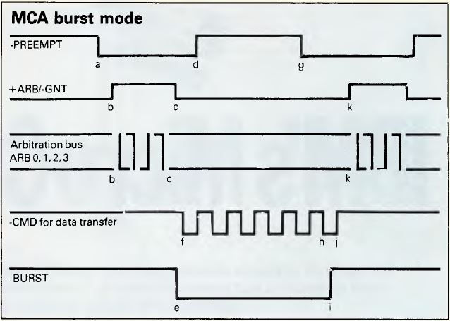
Figure 1. MCA Burst Mode
Figure 1 shows the timing relationship between the signals described
above when burst mode occurs. The sequence of actions is as described
below:
- The —PREEMPT signal goes active to indicate a device is requesting
control of the channel.
- The +ARB/—GNT signal goes to the arbitrate state and the arbitration
procedure starts to determine the highest priority.
- After the time-out period which allows the arbitration bus to settle, the
CACP changes the +ARB/—GNT signal to the grant state.
- The device granted to the channel makes its —PREEMPT signal inactive to
clear its request for control.
- As a burst mode device, it then makes the —BURST line active to enable it
to keep the channel for more than one transfer.
- It then transfers data with each cycle of the —CMD signal.
- If another device requires the channel, it makes the —PREEMPT line
active. Since there is a burst transfer in progress, the CACP takes no
immediate action.
- The controlling device can do some more transfers to enable it to suspend
its actions tidily.
- The —BURST line is released after the leading edge of the last —CMD
pulse in the transfer.
- On the trailing edge of the last —CMD pulse, the CACP will action the
outstanding —PREEMPT signal (as there is no longer a burst occurring).
- The CACP makes the +ARB/—GNT signal go to the arbitrate state and the
process begins again.
As described above, a high-priority bursting device would in fact only
relinquish the channel for one cycle and then grab it back again. The simple
algorithm above runs the risk of a high-priority high-bandwidth device
'hogging' the channel. To prevent this, each device which implements burst mode
must also implement the fairness algorithm which guarantees each device a share
of the channel in a priority determined sequence. When a bursting device
relinquishes control, it is placed in the 'hogpen' (known more formally as the
Inactive State Queue) and must wait until the common —PREEMPT line goes
inactive before it competes for the channel again.
The common —PREEMPT line will only go inactive once all competing devices
have had access to the channel. When —PREEMPT does go inactive, all the
'hogs' are released and will participate in the immediately following
arbitration cycle.
Since a burst-mode device can utilize all of the available bandwidth if
there are no other competing devices, the use of the burst mode can produce
significant increases in the effective transfer rate of a device.
Each device on the channel must use a unique arbitration level or the above
arbitration system would result in two devices, each thinking it had control of
the channel, and the uniqueness of the arbitration levels is checked during
POST (Power On System Test). Each adapter must allow its arbitration level to
be program-selectable to any of the available arbitration levels (0-15). In
practice, the configuration utilities will never select level 15 as this would
clash with the system processor.
This requirement means that there can never be more than 15 active on the
channel at any one time. The POST will disable some cards if more than 15 are
active on the bus on power-up.
DMA ports 1,2,3,5,6,7 have a fixed matching arbitration level, but DMA ports
0 and 4 have a programmable arbitration level. The allocation of arbitration
levels is shown in Figure 2.
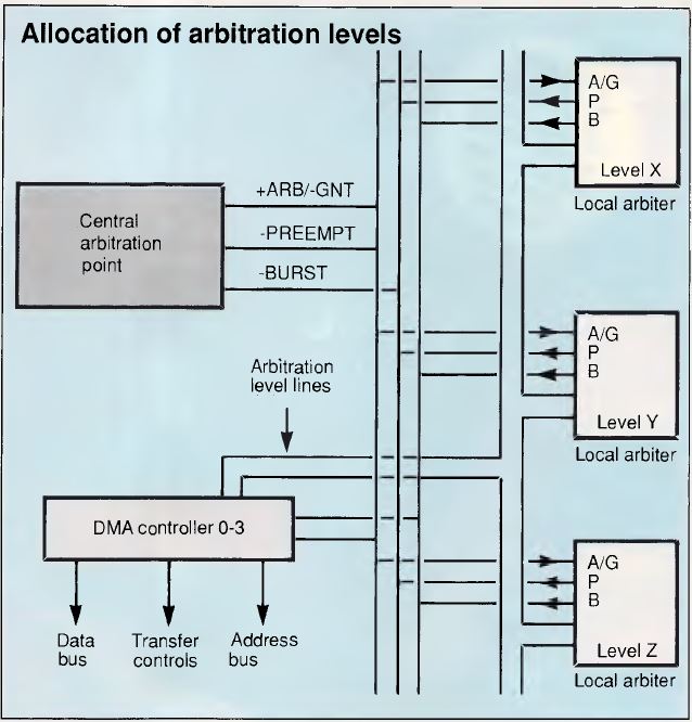
Figure 2. Allocation of arbitration levels
As can be seen in Figure 3, memory refresh has the highest priority
and is initiated from the CACP, and the system board processing has the lowest
priority (excluding the hogpen). The reason that the processor is allocated the
lowest priority is that it continually uses the channel to fetch instructions
and the data manipulated by the instructions. Input/output devices only need
sporadic access to the channel since their data rate is often very low (for
example, a 9600-baud serial link only needs to transfer a byte over 1000
microseconds). Even adapters which need to transfer data at a high rate do not
do so continuously but in short bursts (for example, an Ethernet adapter sends
and receives data at more than 1Mbyte per second but may only process 50
packets every second).
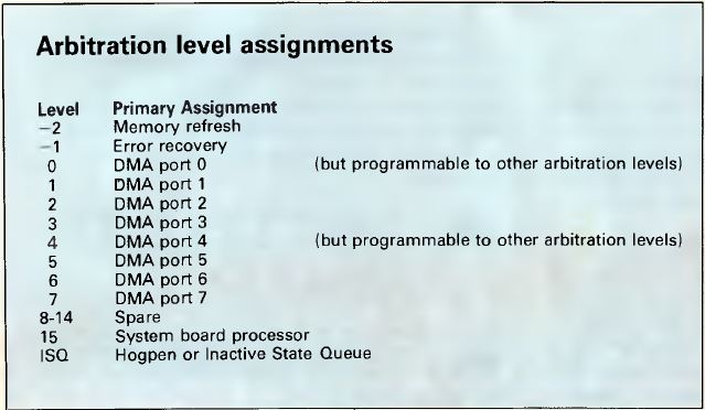
Figure 3. Arbitration level assignments
Since the processor is the lowest priority device it can retain the channel
once it has control without the overhead of arbitration requests, until one of
the other devices signals that it needs to use the channel by activating the
—PREEMPT signal. This means that an arbitration cycle is only required when a
device other than the system board processor requires the channel.
Note: Processor doesn't need further arbitration
requests to control channel (unless another device raises —PREEMPT) since it's
the lowest priority... -LFO
The performance benefits of using burst mode on the new Micro Channel are
such that a disk, for example, can transfer data twice as fast across the
channel as it could across the AT bus.
MCA Reliability
In the description of the Multi Device Arbitration Interface, it was stated
that the central arbitration control point will not initiate an arbitration
cycle while a device is asserting the —BURST signal. If a burst-mode device
were to gain control of the channel and then refuse to release control, memory
refresh operations would be impeded which would cause soft-memory errors.
To protect the system from such devices the CACP implements a timeout, which
is started when —PREEMPT goes active and gives the bursting device 7.5
microseconds to release control. After the time-out period has passed, the CACP
will place the +ARB/—GNT line in the arbitrate state and therefore remove the
grant from the bursting device. The memory refresh activity has the highest
possible arbitration level and will set —PREEMPT every 15.6 microseconds to
enable a refresh to occur.
Note: If device asserts —BURST, it can control
the bus for a max of 15.6 µs before memory refresh has to happen. After
the memory refresh happens, control of bus is returned to device that assets
—BURST. DIMM memory suggests effective bus control is about 12 µs...
-LFO
Any memory card or device which detects an error that threatens the correct
continued operation of the system must drive the channel check (—CHCK) signal
active, and it must remain low until the —CHCK interrupt handler resets it.
In addition, the card must set the channel check bit in the card's option
select address space. This bit is interrogated by the —CHCK handler for each
card position until all reporting cards have been identified.
Level-sensitive Sharing Interrupts
All the Micro Channel system board features and channel attached devices
employ the same level-sensitive mechanism for interrupting the processor. Each
card must also implement an interrupt pending indicator which is reset by the
normal servicing of the device. Each card must hold the level-sensitive
interrupt active until it is reset as a direct result of servicing the
interrupt. The advantages of the new structure are as follows.
Phantom or lost interrupts should be less frequent and more easily
identified as there is an interlock between the hardware and software that
supports the interrupt service. With the previous PC bus, interrupts were 'edge
sensitive' which meant that it was the change from inactive to active state
which caused the interrupt request into the processor. With a level-sensitive
interrupt, the interrupt request into the processor remains pending until the
device makes the signal inactive in response to the normal servicing of the
interrupt.
With edge-sensitive interrupts an interrupt could be lost if it occurred
while a previous interrupt was still being serviced, as the interrupt signal
was already in the active state. The second interrupt could not cause the
inactive-to-active transition and, therefore, the processor was not notified of
the second interrupt. With level-sensitive interrupts, each interrupt request
will be notified to the processor.
The importance of this change to the reliability and flexibility of the
system is underlined by the fact that IBM has built circuitry into the system
board which prevents any attempt to re-program the interrupt controller to
operate in edge sensitive mode.
Each interrupt level can be used by a mixture of sharing and non-sharing
hardware. An interrupt handler which is to be used in a shareable environment
must follow certain rules to enable the system to operate. When the interrupt
handler is set up, it must note the address of any existing handler for the
interrupt level. When the interrupt level handler is invoked to process an
interrupt, it must check that the adapter that it is handling has an
outstanding interrupt request by accessing the interrupt pending bit on the
adapter. If the adapter is in the process of interrupting, it is serviced
normally and the interrupt controller is reset.
If any other card on the same level still requires service, then the
interrupt request line will still be active and cause the chain of interrupt
handlers to be reentered. If the handler finds that the adapter does not have
an interrupt pending, then it passes control to the previously existing
interrupt handler. In this way, control is passed down the chain of interrupt
handlers until all requesting devices are serviced.
An interrupt level can in fact be shared between a device on the system
board and a device attached to the channel service system board as long as the
devices conform to the standard rules. It should be noted, however, although
many devices can share an interrupt level, the time between the interrupt being
raised and the appropriate interrupt handler processing the interrupt increases
as the number of devices increases.
Multiple Masters
To understand the benefits which can be gained from the use of an additional
master on the channel, we need to understand the actions of the system board
processor and the DMA controller when transferring data to and from a device.
It should be noted that each port of the DMA controller on the system board is
in effect a master but one with very limited abilities.
We will consider what is involved in the case where some data is being
transferred from one device on the channel to a second device on the channel
— for example, when a file is being copied from one disk to another.
In the case where the processor is directly handling each device we would
have the situation where the processor would be interrupted for each incoming
byte, and would then execute code to identify the source of the interrupt as
well as transfer the data from the device to the processor. It would then have
a similar set of actions to write the data out to the destination device.
Hence, each byte crosses the channel twice and there is a significant processor
overhead servicing the devices (which will involve further memory accesses
across the channel). Servicing each interrupt and organizing the transfer to or
from the device can cost at least 100 processor instructions to be executed for
each byte transferred. This is shown in Figure 4.
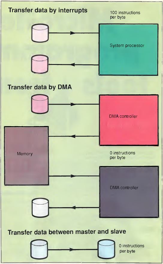
Figure 4. Data Transfers
The DMA controller can be used to transfer a block of data with a greatly
reduced processor overhead. The processor would instruct the DMA controller to
transfer a block of data from the input device but would not be involved in the
transfer of each byte. The use of the DMA controller means that the byte would
be transferred across the channel from the device to the DMA controller, and
then again across the channel to the memory area specified by the processor.
The same double transfer would occur when the data is being transferred to the
output device. Therefore, the use of the DMA controller would cause each byte
to transfer across the channel four times (but would still be more effective
because of the greatly-reduced system processor overhead). This, too, is shown
in Figure 4.
In the case where one of the devices is a master it can control the other
device directly as a slave, and the master can process interrupts from the
slave directly off the channel without involving the system processor. If, for
example, the input device is the master, it can directly transfer each received
byte to the output device with each byte being transferred across the channel
only once, and the cost to the system board processor of setting up the master
is probably less than the cost of setting up the two DMA operations. This is
shown in Figure 4.
From the above example, it can be seen that the use of a master device can
require only 25 per cent of the channel transfers that are needed by a DMA
controller while requiring no additional processor overhead.
Enter OS/2
The real power of multiple masters will only be really exploited when the
master becomes capable of providing a significant amount of functions for each
request from the system board (or, indeed, some other master).
One possible such master would be a complete file system with internal disk
drive(s) and controller which would respond to OS/2 or DOS level file access
requests. Such a master would carry out the directory searches and the
maintenance activities (such as updating the FAT) with no channel accesses, and
only the requested data being transferred across the channel. It would support
multiple simultaneous transfer requests and use various techniques to optimize
access to the integral disks. In the case of the example presented here, the
file copying could be achieved without any data being transferred across the
MCA interface and with no interference to the operation of the system board
processor.
Such intelligent masters cannot be fully exploited or cost-justified when
PC-DOS is being used since DOS waits for each transfer to complete before
continuing with the application. Under DOS, such masters would provide very
little obvious performance benefit since the elapsed time to access the data is
likely to be approximately the same and DOS is unable to utilize the processor
savings. With OS/2, however, the situation is completely different. While one
application is held waiting for its data to be processed by the master device,
OS/2 will be able to schedule other activities and so fully utilize the
processor time which is made available by the use of the intelligent
master.
We are accustomed to and familiar with changes which improve the performance
of our PC-DOS systems, such as when we upgrade the clock speed from 4.77 MHz to
8 MHz, or change from an 8088 to 80286 processor, or move from a floppy disk to
a hard disk. Such changes speed up each individual activity noticeably. With
OS/2 and MCA, however, we will have to become accustomed to changes which
increase the overall power of our systems but which will not necessarily make
any single activity operate any faster. One of the main benefits of MCA is that
it gives IBM and other suppliers a platform on which such total system
improvements can be built.
It is possible that at some point in the future the database and comms
manager services for IBM's OS/2 extended edition will be offered by separate
masters which have been optimized to provide the required high-performance
service with minimum impact on the main system processor.
Conclusion
IBM has always stated that its reason for changing to MCA was to support
fully and exploit a multi-tasking system such as OS/2. We have seen how MCA
provides support for simultaneous transfers over the interface, and this is
paralleled within OS/2 by the advanced BIOS also providing support for such
concurrent activity. The availability of intelligent masters on the MCA
interface further enhances the ability of the complete system to deliver a
significant increase in total power when OS/2 is being used.
The design of the Micro Channel enables the PS/2 systems to be inherently
more reliable than the previous PCs or ATs, even in complex environments with a
multi-tasking operating system such as OS/2. The support for multiple masters
lays the groundwork for providing powerful systems in which the major
subsystems can be partitioned to operate in separate processors communicating
over the Micro Channel. It is obvious that what IBM has currently announced is
only the tip of a very large iceberg.
|