|
Basic Transfer Procedure
Default Cycle (≥200 ns)
Synchronous Extended Cycle (≥300 ns)
Asynchronous Extended Cycle (≥300 ns)
Basic Transfer Procedure
All masters and DMA controllers transfer data with the same
control sequence. The following covers the case of a write cycle.
The signals appear in the following sequence:
The master drives the address bus, MADE 24, M/-IO,
-APAREN, APAR(0-3) and -REFRESH (if applicable) valid,
beginning the cycle. In response to an unlatched decode of address, MADE 24,
and M/-IO, the selected slave returns:
- -CD SFDBK
- -CD DS 16 (if the addressed data port is capable of 16-bit operations)
- -CD DS 16 and -CD DS 32 (if addressed data port is capable of 32-bit operations)
The master drives status signal -S0 active (-S1
inactive.) In response to an unlatched decode of address, MADE 24,
M/-IO, and status, the selected slave drives CD CHRDY inactive
if the cycle is to be extended. The master drives -ADL active. A slave can latch decodes
of address, status, and M/-IO at the leading or trailing
edge of -ADL. A DMA slave can also be selected by a latched
decode of the same signals, using the arbitration level in
place of the address. The master drives the write data onto the data bus and,
if appropriate, drives -DPAREN active and DPAR(0-3) valid. The master drives -CMD active and -ADL inactive. A slave
must latch the decodes of address, status, and M/-IO with
the leading edge of -CMD if they weren't latched with -ADL. If CD CHRDY has been driven inactive, the cycle is
extended until CD CHRDY is driven active. The signal must
not be held inactive longer than specified. The status signals become inactive and the address bus
can change in preparation for the next cycle. In response to an address change, the slave updates the
state of:
- -CD SFDBK
- -CD DS 16
- -CD DS 32.
The status signals and M/-IO can become valid in
preparation for the next cycle. -CMD goes inactive and the selected slave receives the
data from the data bus.
The data transfer cycle is complete.
Note: The changes to the
address bus and status (-S0, -S1) can be overlapped with the
preceding cycle to minimize the impact of the memory access
time.
The sequence for the basic transfer procedure is as follows.
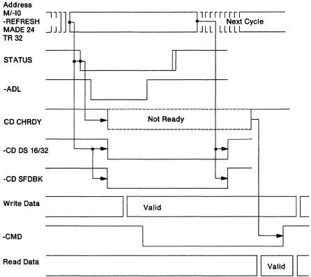
Figure 1-22. Basic Transfer Procedure - Overview
Whether a default, a synchronous-extended, or an
asynchronous-extended cycle is performed depends on how
a slave uses CD CHRDY.
A default cycle occurs when a slave does not
drive CD CHRDY inactive. A synchronous-extended cycle occurs when a
slave drives CD CHRDY inactive, then releases CD CHRDY
synchronously within the specified time after the leading
edge of -CMD. The slave provides the read data within the
specified time from -CMD active. An asynchronous-extended cycle occurs when a
slave drives the CD CHRDY inactive, then releases CD CHRDY
asynchronously.
If a master begins a transfer cycle but must abort that
cycle, -ADL and -CMD must not be activated, and -S0, -S1
must be activated with a minimum pulse width T2A (see Figure
1-24 on page 1-34 for the T2A timing specification). -BURST,
if active, is deactivated with status deactivation. Slaves
must not latch CD CHRDY inactive until after the appearance
of an active -ADL signal, and if the cycle is aborted, must
release CD CHRDY with the deactivation of status. The
selected slave degates the data bus and data transfer
control signals when it is no longer selected (status and
-CMD are inactive).
Default Cycle Timing (200 ns Minimum)
This section provides the specifications for the timing
parameters for the I/O and memory default transfer cycle.
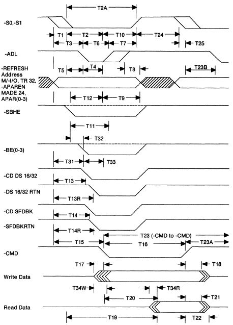
Figure 1-23. Default Cycle (200 ns Minimum)
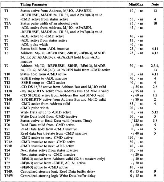
Figure 1-24. Default Cycle (200 ns Minimum) Timing
Specifications
Notes:
Slaves drive -CD SFDBK when selected by either
arbitration or address. The slave does not drive -CD SFDBK
active when selected by -CD SETUP. The master must hold the address bus and associated
signals valid until -DS 16 RTN, -DS 32 RTN, and -SFDBKRTN
are sampled, in addition to meeting T5 and T9. The slave
must continue to drive -CD DS 16/32 and -CD SFDBK as long as
its address is valid. A master can deactivate status and address concurrently.
This can result in changes on the address bus while status
is still active at the slave. CD CHRDY can change states
during changes on the address bus. It is recommended that slaves use transparent latches to
latch information with the leading edge of -CMD, or with the
leading or trailing edge of -ADL. When data parity is supported, the implemented data
parity signals must be active and stable on the bus for the
data to be considered valid. -CD DS 16/32 and -CD SFDBK must be driven by unlatched
address decodes because the next address can be driven
valid in the current cycle When address parity is supported, the implemented address
parity signals must be active and stable for the address to
be considered valid. Tl9 is a valid timing parameter only when T2 is less than
65 nanoseconds. The centralized steering delay applies when a 16-bit
master accesses a 32-bit data port. The slave must
compensate for the centralized steering delay, as required.
Masters must provide this minimum timing for the central
arbitration control point and for inactive state exit. Other
participants must not depend on this minimum during an abort
cycle. (See "Central Arbitration Control Point" on page 1-21
for more information.) A bus master must deactivate -S(0,1) as soon as possible
after the hold time specified by T7 and T10, and prior to
the deactivation of -CMD. Additional rules apply for
extended cycles and streaming data cycles. If data parity is used, see T96 timing in Figure 1-71 on
page 1-86. TR 32 can be held inactive between cycles by a 32-bit
master. TR 32 timings are provided to define when it must be valid
on the first and last cycle.
Synchronous-Extended Cycle Timing (300 ns Minimum)
A synchronous-extended cycle occurs when a slave drives CD
CHRDY inactive, then releases CD CHRDY synchronously within the
specified time after the leading edge of -CMD.
The timing sequence is shown in the following figure
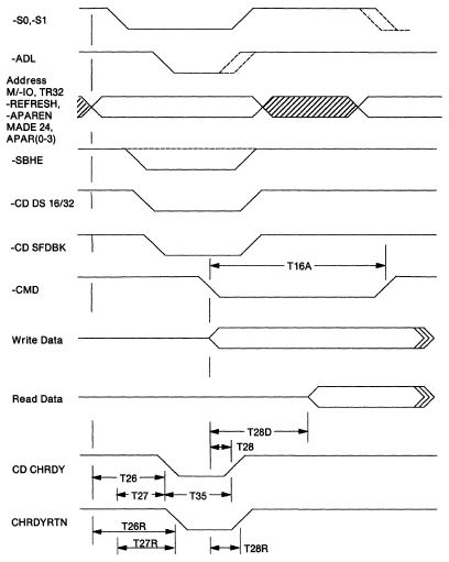
Figure 1-25. Synchronous-Extended Cycle (300 ns Minimum)
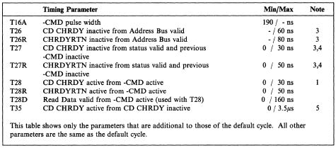
Figure 1-26. Synchronous-Extended Cycle Timing Specifications
(300 ns Minimum)
Notes:
CD CHRDY is released by a slave performing a 300
nanoseconds extended cycle within the specified time after
the leading edge of -CMD. A master can deactivate status and address concurrently.
This can result in changes on the address bus while status
is still active at the slave. CD CHRDY can change states
during changes on the address bus. T27 and T27R apply only when Tl is greater than 30
nanoseconds. T26 and T26R applies only when Tl is less than
or equal to 30 nanoseconds. Masters are responsible for controlling their own bus
activity. When a master uses overlapped cycles, it must be
capable of handling (or ignoring) CD CHRDY from the next
slave while terminating the cycle with the current slave.
Once the current cycle is terminated, the master must act
appropriately to an inactive CD CHRDY signal. Masters must
also recognize and handle any added delay in a slaves
deactivation of CD CHRDY caused by overlapped cycles. A bus master must deactivate -S0, -S1 as specified in the
default cycle, and this deactivation must be independent of
CHRDYRTN. Slaves should not depend on the removal of -S0,-S1
for the deactivation of CD CHRDY. When address parity is supported, the address parity
signals (APAR 0-3) must be active and stable for the address
to be considered valid.
Asynchronous-Extended Cycle Timing (300 ns Minimum)
An asynchronous-extended cycle occurs when a slave drives CD
CHRDY inactive, then releases CD CHRDY asynchronously.
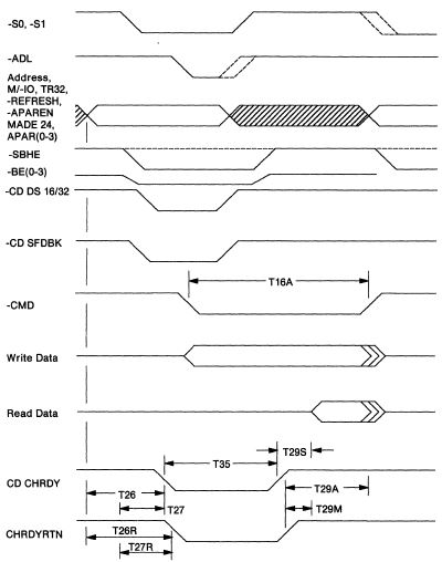
Figure 1-27. Asynchronous Extended Cycle (300 ns Minimum)
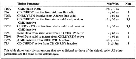
Figure 1-28. Asynchronous-Extended Cycle Timing Specifications
(300 ns Minimum)
Notes:
CD CHRDY is released asynchronously by a slave performing
a ≥300-ns cycle. The slave must present the read data within
the time specified after the release of CD CHRDY. A master can deactivate status and address concurrently.
This can result in changes on the address bus while status
is still active at the slave. CD CHRDY can change states
during changes on the address bus. T27 and T27R apply only when T1 is greater than 30
nanoseconds. T26 and T26R apply only when T1 is less than or
equal to 30 nanoseconds. Masters are responsible for controlling their own bus
activity. When a master uses overlapped cycles, it must be
capable of handling (or ignoring) CD CHRDY from the next
slave while terminating the cycle with the current slave.
Once the current cycle is terminated, the master must act
appropriately to an inactive CD CHRDY signal. Masters must
also recognize and handle the potential added delay in a
slave's deactivation of CD CHRDY due to overlapped cycles. A bus master must deactivate -S0, -S1 as specified in the
default cycle, and this deactivation must be independent of
CHRDYRTN. Slaves should not have dependencies on removal of
-S0, -S1 for the deactivation of CD CHRDY. When address parity is supported, the implemented address
parity signals (APAR 0-3) must be active and stable for the
address to be considered valid.
|