|
Single Transfer
Burst Transfer
Single Transfer:
During a data transfer, the
requesting DMA slave initiates the DMA operation by having
its arbiter drive -PREEMPT active and arbitrate for the
channel. On the low-to-high transition edge of ARB/-GNT
(start of arbitration cycle), the DMA slave's priority level
is placed on the arbitration bus. The DMA slave competes for
use of the channel as defined in the arbitration procedure.
On the high-to-low transition edge of ARB/-GNT the DMA
controller monitors the arbitration bus to determine if its
DMA slave gained control of the channel. A match initiates a
serial DMA operation in which the DMA controller drives the
address lines during both cycles, as well as driving -S0,
-S1, -CMD, and other control signals. The DMA controller
also monitors -BURST, finds it inactive, and then activates
-BURST (either on the channel, or through the system logic)
to notify the central arbitration control point that
consecutive cycles are required.
The DMA controller also manages the storage of data during
the DMA read or DMA write operations for the consecutive
cycles required by serial DMA transfers. Data count for data
gated on or off the bus by the DMA slave is also maintained
by the DMA controller.
Notes:
The DMA controller might be required to perform multiple
cycles for the data transfer to the memory slave, if the
data port width of the memory slave is less than that of the
DMA slave. DMA slaves using single-transfer type DMA procedure will
not receive more data than is required to support their data
port width (for example, 2 bytes to a 16-bit port). Consecutive transfers can be made with the DMA slave (as
opposed to the serial sequences shown in the remainder of
this section.) The memory read or write cycles might not
appear on the channel.
Burst Transfer
(Multiple Transfer Cycles): The
method for transferring a block of data is similar to a
single transfer DMA cycle, except that the local arbiter for
the requesting DMA slave activates -BURST to request
continued channel ownership for a burst operation. The
central arbitration control point will not drive ARB/-GNT to
the ARB state while -BURST is active. As in single-transfer
DMA operations, the DMA controller drives the address, -S0,
-S1, -CMD, and data transfer signals, as well as manages
addresses and data transfer counts. The DMA controller also
drives -BURST (either on the channel or through the system
logic) jointly with the DMA slave for DMA write cycles. It
does not drive -BURST active for burst DMA read cycles.
DMA Terminating Conditions:
The DMA transfer operation is terminated by the EOT. At this
time, a DMA slave can again request DMA service by
arbitrating for use of the channel.
The terminating conditions for DMA transfers are:
- Single transfer, DMA controller can terminate the DMA
transfer by releasing -BURST.
- Burst transfers, either DMA slave or DMA controller can
terminate the DMA operation.
The DMA slave terminates the transfer by driving -BURST
inactive. The DMA slave will terminate the transfer when it
reaches its buffer limit, or after -PREEMPT is driven active
by another arbitrating participant. Arbitrating slaves
should maximize use of the channel within the 7.8
microsecond time limit.
The DMA controller terminates the transfer by driving -TC
active when the transfer count goes to zero. When the DMA
slave receives -TC, it drives -BURST inactive.
Use of -BURST: When a bursting
DMA slave wins the arbitration for the channel, it drives -BURST active.
During default cycles, the DMA slave drives -BURST inactive when it
detects status active for the last I/O cycle of this burst transfer.
However, on sensing -SBHE and/or -BE(0-3), the DMA slave might discover
that it has one more cycle to perform. If so, it redrives -BURST active
to continue the transfer (See "Burst DMA Transfer (DMA-Slave Terminated
- Default Cycle, 200 ns)" on page 1-67). During extended cycles, the DMA
slave drives -BURST inactive within the specified time after the leading
edge of -CMD.
If a burst transfer is terminated by the DMA controller, the DMA
slave drives -BURST inactive within the specified time after the leading
edge of -TC. For DMA write cycles using burst transfer, the DMA
controller drives -BURST active at the leading edge of -CMD for each I/O
read and drives it inactive when it detects status active for the
next memory write.
Single DMA Transfer (DMA-Controller Controlled)
The following are the timing parameters for the DMA procedure.
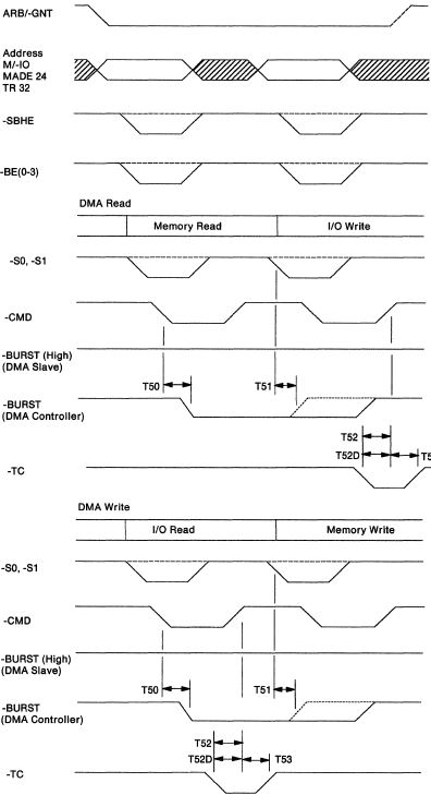
Figure 1-50. Single DMA Transfer (DMA-Controller Controlled)

Figure 1-51. Single DMA Transfer (DMA-Controller Controlled)
Timing Specifications
Notes:
Only timing parameters that are additional to those
specified for basic transfer cycle are included here. T52D applies to participants operating at 200 ns cycles
only. Devices operating at cycle rates slower than 200 ns
must meet T52. For streaming data procedures, T80 and T81 also apply.
(See "Streaming Data Timing" on page 1-56)
Burst DMA Transfer (DMA-Controller Terminated)
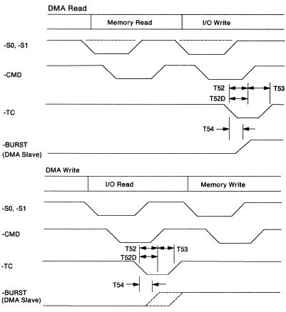
Figure 1-52. Burst DMA Transfer (DMA-Controller Terminated)

Figure 1-53. Burst DMA Transfer (DMA-Controller Terminated)
Timing Specifications
Notes:
T52D applies to devices operating at 200 ns cycles only.
Devices operating at cycle rates slower than 200 ns must
meet T52. During DMA read, the DMA controller must not initiate
another cycle after issuing -TC, even if the DMA slave is
not fast enough to drive -BURST inactive before the end of
-CMD. For streaming data procedure, T80 and T81 also apply.
(See "Streaming Data Timing" on page 1-56)
Burst DMA Transfer (DMA-Slave Terminated - Default Cycle, 200 ns)
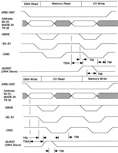
Figure 1-54. Burst DMA Transfer (DMA-Slave Terminated - Default Cycle, 200 ns)

Figure 1-55. Burst DMA Transfer (DMA-Slave Terminated -
Default Cycle, 200 ns) Timing Specifications
Notes:
After releasing -BURST and on receiving -SBHE and/or
-BE(0-3), if the DMA slave determines that it requires
another cycle, it can re-drive -BURST active. The setup time for -BURST inactive to the end of -CMD
(T56) must be guaranteed during the last I/O write cycle to
prevent the DMA controller from starting the next cycle.
This setup time (T56) is guaranteed by the sum of -BURST
release time (T55/T55A controlled by the DMA slave) and the
-BURST RC restoration time. The RC restoration time must not
exceed 70 nanoseconds. T56 is the same for default and
extended cycles.
Burst DMA Transfer (DMA·Slave Terminated - Synchronous-Extended Cycle, 300 ns)
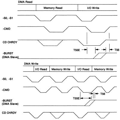
Figure 1-56. Burst DMA Transfer (DMA-Slave Terminated -
Synchronous-Extended Cycle)

Figure 1-57. Burst DMA Transfer (DMA-Slave Terminated -
Synchronous-Extended Cycle, 300 ns) Timing Specifications
Notes:
The setup time for -BURST inactive to the end of -CMD
(T56) must be guaranteed during the last I/O write cycle to
prevent the DMA controller from starting the next cycle.
This setup time (T56) is guaranteed by the sum of -BURST
release time (T55E controlled by the DMA slave) and the
-BURST RC restoration time. The RC restoration time must not
exceed 70 nanoseconds. T56 is the same for default and
extended cycles. -BURST cannot be redriven.
Burst DMA Transfer (DMA Slave Terminated - Asynchronous-Extended Cycle, ≥300 ns)
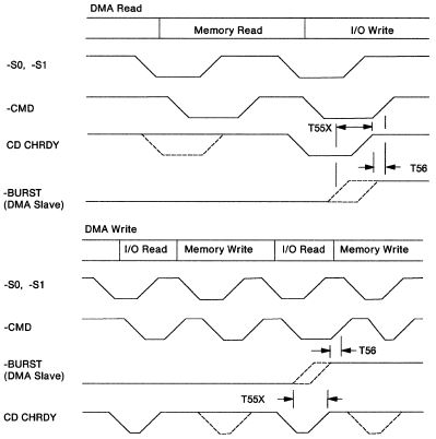
Figure 1-58. Burst DMA Transfer (DMA-Slave Terminated -
Asynchronous-Extended Cycle, ≥300 ns)

Figure 1-59. Burst DMA Transfer (DMA-Slave Terminated -
Asynchronous-Extended Cycle, ≥300 ns) Timing Specifications
Notes:
Setup time for -BURST inactive to the end of -CMD (T56)
must be guaranteed during the last I/O write cycle to
prevent the DMA controller from starting the next cycle.
This setup time (T56) is guaranteed by the sum of -BURST
release time (T55X controlled by the DMA slave) and the
-BURST RC restoration time. The RC restoration time must not
exceed 70 ns. T56 is the same for default and extended
cycles. -BURST cannot be redriven.
|