|
Streaming Data Transfer
The streaming data procedure provides performance
improvements over basic transfer procedures for block
transfers, and supports data-transfer rates of up to 80MB
per second. It provides for the transfer of a data block by
using a single address followed by multiple 16-, 32-, or
64-bit data transfers within a single streaming data cycle.
The data transfers are clock-synchronous and incorporate
automatic speed matching between the controlling
master and slave.
The streaming data procedure can be used for high speed data
transfer between a controlling master and the selected
slave. The streaming data procedure is transparent to
devices that are not selected. Streaming data participants
must support the basic transfer procedure to operate with
nonstreaming-data participants. Special rules apply to
streaming data devices to ensure compatibility with
nonstreaming-data participants. These include:
A streaming-data-enable bit must be supported in the
adapter POS space.
Note: Streaming data
participants must support a fully-functional operation with
nonstreaming-data participants, independent of the state of
the Streaming Data Enable field. After CHRESET, the default state of the
streaming-data-enable bit is disabled. Both 16- and 32-bit streaming data transfers must start on
four-byte address boundaries. A 64-bit streaming data transfer must be aligned on an
eight-byte address boundary.
Data is validated by using CD CHRDY to indicate ready or not
ready, so that the slave has the ability to pace the data
transfer for 16- or 32-bit transfers. Either the master or
slave can terminate the cycle at any time.
Implementing and using streaming data transfer is optional
to masters.
Implementing and indicating streaming data transfer
capabilities is optional to slaves.
Streaming Data Procedure (16- or 32-Bit)
A 16- or 32-bit streaming data transfer cycle is initiated
as either a 16- or 32-bit
basic data transfer cycle, and all rules associated with
those procedures apply. The
following is an example of a 16- or 32-bit streaming data
write cycle. The signals
appear in the following sequence:
The master drives the address bus, MADE 24, M/-10,
-APAREN, and APAR(0-3) valid
to begin the cycle. In response to an unlatched decode of address, MADE 24,
and M/-IO, the selected
slave returns:
- -CD SFDBK
- -CD DS 16 (if the addressed data port is capable of 16-bit operations)
- -CD DS 16 and -CD DS 32 (if the addressed data port is capable of 32-bit operations)
The master drives -S0 active (-S1 inactive). In response to an unlatched decode of address, MADE 24,
M/-IO, and status, the
selected slave drives CD CHRDY inactive, if the cycle is to
be extended. A 32-bit master (or the central translator logic for a
16-bit master in a 32-bit system) drives the byte enable
signals. -BE(0-3) is driven to binary 0011 by the central
translator logic, or -BE(0-3) is driven to binary 0000 by a
32-bit master.
Note: Because 32-bit
operations are aligned on four-byte boundaries, A0, A1, and
-SBHE equal a binary 000. The master drives -ADL valid. A slave can latch decodes
of address, status, and
M/-IO at the leading or trailing edge of -ADL. The slave drives -SDR(0,1) active.
Note: When the slave
does not drive -SDR(0,1) active (indicating that it is
defaulting to basic transfer procedures), the controlling
master will drive -S(0,1) inactive after the hold time
specified by timing parameter T7 and T10 (see Figure 1-24 on
page 1-34). The master drives the write data onto the bus and, if
supported, drives -DPAREN active and DPAR(0-3) valid. The master drives -CMD active and -ADL inactive. A slave
must latch the decodes of address, status, and M/-IO with
the leading edge of -CMD if they were not latched with -ADL. If CD CHRDY has been driven inactive, the cycle is
extended until CD CHRDY is driven active. CD CHRDY must not
be held inactive longer than specified. The controlling master indicates the ability to perform
streaming data by starting -SD STROBE.
Note: If CHRDYRTN is
active, -SD STROBE can be activated concurrently with -CMD.
-SD STROBE is used by both the controlling master and slave
to transfer data, with data being clocked on and off the bus
on the falling clock edge and clocked off the bus on the
next falling clock edge. The operation proceeds with new
data being placed on the bus every time -SD STROBE makes a
high-to-low transition. The master drives status inactive. The slave drives -SDR(0,1) inactive. The address bus can change in preparation for the next
cycle. In response to an address change, the slave updates the
state of:
- -CD SFDBK
- -CD DS 16
- -CD DS 32.
The status signals and M/-IO can become valid in
preparation for the next cycle. The master stops driving -SD STROBE. On the last transfer, the controlling master drives -CMD
inactive, and the selected slave gates the data off the bus.
The transfer cycle is complete.
Streaming Data Procedure (64-Bit)
A 64-bit streaming data transfer cycle is initiated as a
32-bit basic transfer cycle, and all the rules associated
with this procedure apply. The following is an example of a
64-bit streaming data write cycle. The signals appear in the
following sequence:
The master drives the address bus, MADE24, M/-IO,
-APAREN, and APAR(0-3) valid to begin the cycle. In response to an unlatched decode of address, MADE24,
and M/-10, the selected slave returns:
- -CD SFDBK
- -CD DS 16
- -CD DS 32
The master drives -S0 active (-S1 inactive). In response to an unlatched decode of address, MADE24,
M/-IO, and status, the selected slave drives CD CHRDY
inactive, if the cycle is to be extended. A 32-bit master drives -BE(0-3) to binary 0000 (64-bit
streaming data transfers are not performed by 16-bit
masters).
Note: Because 64-bit
operations are aligned on an eight-byte boundary, A0, A1,
and -SBHE equal binary 000. The master drives -ADL active. A slave can latch decodes
of address, status, and M/-IO at the leading or trailing
edge of -ADL. The slave drives -SDR(0,1) to indicate its transfer speed
capability and drives -MSDR active to indicate 64-bit
capability.
Note: When the slave
does not drive -SDR(0,1), and -MSDR active (indicating that
it is defaulting to a basic transfer procedure), the
controlling master drives -S(0,1) inactive after the hold
time specified by timing parameters T7 and T10, and prior to
driving -CMD active. (See Figure 1-24 on page 1-34.) The master drives the write data onto the data bus and,
if supported, drives -DPAREN active and DPAR(0-3) valid. The master drives -CMD active and -ADL inactive. A slave
must latch the decodes of address, status, and M/-IO with
the leading edge of -CMD if they were not latched with -ADL. If CD CHRDY has been driven inactive, the cycle is
extended until CD CHRDY is driven active. CD CHRDY must not
be held inactive longer than specified. The controlling master indicates the ability to perform
streaming data transfers by activating -SD STROBE. The
64-bit streaming data transfer capability is indicated by
driving -BE(0-3) inactive, driving the four most significant
bytes of the eight byte transfer on the address bus, and, if
-DPAREN is active, driving APAR(0-3) valid. -APAREN is
driven inactive.
Note: -SD STROBE is used
by both the controlling master and the slave to transfer
data; data is clocked on and off the address bus and the
data bus on the falling clock edge and clocked off the
address bus and the data bus on the next falling clock edge.
The operation proceeds with the new data being placed on the
address bus and the data bus each time -SD
STROBE makes a high-to-low transition. Both the address bus and data bus are used for
transferring data for the remainder of the cycle. The status signals are driven inactive on the last high
to low transition of -SD STROBE. The slave drives -SDR(0,1)
inactive. In response to data on the address bus, other slaves can
drive -CD SFDBK, -CD DS 16, -CD DS 32, and CD CHRDY valid
during the data transfer. The master should not monitor the
state of these signals during the data transfer. On the last transfer, the controlling master drives -CMD
inactive and the slave gates the data off the address bus
and the data bus. The cycle is complete.
Streaming Data Transfer Rates
The amount of data transferred per -SD STROBE period is
constant during streaming data transfer. The number of bytes
transferred in one transfer cycle are listed below.
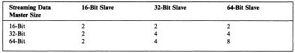
Figure 1-33. Streaming Data Transfer Rates
Note: When a slave
requests a streaming data transfer, it must be prepared to
support a minimum of two transfers. When a master initiates
a streaming data transfer, it must be prepared to support a
minimum of one transfer.
Address Bus Management:
During streaming data transfers, the address on the address
bus is neither incremented nor decremented. The controlling
master and the slave must provide memory-address-space
address management and I/O-address-space address management
as follows:
Memory address space addresses
The controlling master must keep a count of the number of
bytes transferred, so that if early termination of the block
transfer occurs, the master can assert the correct address
(original address plus the number of bytes transferred) at
the start of the next data transfer procedure. The slave
must manage the address, to ensure that the data being
clocked off the bus is gated into the correct memory
addresses. I/O address space addresses
If early termination of the block transfer occurs, the
master must present the same (original) address on the
address bus, when restarting the streaming data procedure.
The slave must accommodate the streaming data transfer to
the same I/O address.
During 64-bit streaming data transfers (after the address is
removed from the address bus), the controlling master must
ignore CHRDYRTN, -DS 16 RTN, -DS 32 RTN, and -SFDBKRTN.
Slaves (except the selected slave) are decoding the address
bus and responding as if selected.
Address Boundary Alignment:
If the starting address is not a four-byte address boundary
and a 16- or 32-bit streaming data procedure is going to be
used, then the basic transfer procedure must be used to
transfer data until the address has the correct boundary
alignment. The controlling master must execute the basic
transfer procedure to obtain address boundary alignment.
A slave can indicate streaming data capability, by driving
-SDR(0,1) active, without checking address boundary
alignment. Then the controlling master and the slave can use
the streaming data procedure. The basic transfer procedure
might also be required to complete the data transfer, even
if the initial data address was a four-byte address
boundary.
If the starting address is not on an eight-byte address
boundary and a 64-bit streaming transfer procedure is going
to be used basic transfer cycles are used to transfer data
until the address has a correct boundary alignment. The
basic transfer procedure might also be needed to complete
the data transfer, even if the initial data address was a
eight-byte address boundary.
The following is an example of a basic transfer procedure
occurring before and after a 16- or 32-bit streaming data
procedure. The controlling master should drive -BURST active
to indicate that one or more consecutive data transfer
cycles will occur. Figure 1-34 shows the data block to be
transferred.
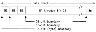
Figure 1-34. Data Block Example
In the above example, the data transfer procedures used to
achieve address boundary alignment between a controlling
master and the selected slave are:
The data address is now on a 32-bit boundary.
Bytes B4 through B(n-1) are transferred using the
streaming data procedure. Each period of -SD STROBE
transfers two or four bytes of data. The streaming data
procedure continues until all data, except byte Bn, is
transferred. The streaming data procedure is terminated. Byte Bn, the last byte is transferred using a basic
transfer procedure. The session between the controlling master and the slave
is terminated.
Streaming Data Cycles
A master can perform streaming data transfers at 10 MHz when
-SDR(0,1) is a binary 00, 01, or 10, and can perform the
transfer at less than the requested width. -SDR(l) is
reserved and slaves should not activate it. The valid
streaming data signal combinations from the selected slave
are shown in the following table.
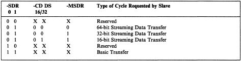
Figure 1-35. Streaming Data Signal Combinations
Both 16- and 32-bit masters can use streaming data
procedures with either 16- or 32-bit slaves. However,
because the central translator logic does not perform data
steering during a streaming data transfer, a 32-bit slave
must perform the steering when streaming with a 16-bit
master. (The 32-bit master does the steering for all data
transfers with slaves having a smaller data port.)
"Streaming Data Procedure (16- or 32-Bit)" on page 1-44 and
"Streaming Data Procedure (64-Bit)" on page 1-46 contain the
general signal sequence overview.
The following describes how:
Masters and slaves select streaming data or basic transfer
procedures, and the number of bits in each transfer. Deferred cycles are performed. Data is paced during streaming data procedures. Streaming data can be terminated by either the master or
the slave.
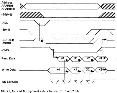
Figure 1-36. 16- and 32-Bit Streaming Data Cycle Overview
64-Bit Streaming Data Cycles
The 64-bit streaming data transfer can only be used between
64-bit streaming masters and 64-bit streaming slaves. An
example of a 64-bit cycle is shown in Figure 1-37 on page
1-51. The 64-bit streaming transfer is similar to the
streaming data transfer shown in Figure 1-36, but uses both
the data bus and the address bus to achieve the 64-bit data
transfer width.
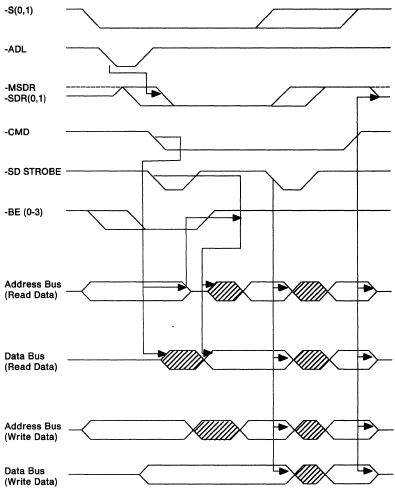
Figure 1-37. 64-Bit Streaming Data Cycle Overview
The 64-bit cycle begins as a 32-bit basic transfer cycle.
The selected slave responds by driving -CD DS 16, -CD DS 32,
-SDR(0,1) and -MSDR valid to indicate that it supports
64-bit streaming operations. -BE(0-3) are driven inactive by
the master to indicate a 64-bit streaming-data procedure
will be used. During a transfer to the slave, the master
starts -SD STROBE and gates the data onto the data and
address buses. During a transfer to the master, the master
tri-states the address bus after driving -CMD active, and,
after the trailing edge of -BE(0-3), the slave gates the
data onto the data and address buses. (The least significant
byte is D(0-7) and the most significant byte is A(24-31).)
The 64-bit streaming transfer then proceeds like a 32-bit
streaming data transfer.
If -DPAREN has been driven active, the parity bits for data
bytes zero through three are contained in DPAR(0-3), the
parity bits for data bytes four through seven are contained
in APAR(0-3).
Deferred start of the 64-bit streaming transfer is
supported, but data pacing is not
available during 64-bit data streaming transfers.
Starting the Cycle:
Streaming masters can drive -SD STROBE active at the same
time as -CMD to minimize the overhead in starting the
streaming data cycle. The T70 time plus propagation delay
for the signals to and from the slave can delay the sample
point of -SDR(0,1) and -MSDR until after -CMD and -SD STROBE
have been activated. Therefore, if a slave indicates it is
capable of performing a streaming data transfer, the master
must perform at least one streaming data transfer. Requiring
one streaming data transfer prevents the slave from
confusing a 32-bit basic transfer with a 64-bit streaming
data transfer.
Deferring the Start of the Cycle:
During a streaming data transfer, the slave may need more
time at the start of the cycle to prepare for the transfer.
The slave can defer the start of the transfer by driving CD
CHRDY inactive. The controlling master delays the start of
-SD STROBE until after CHRDYRTN goes active.
If -SDR(0,1) is not active within the time specified (T70A),
the controlling master continues the cycle using basic
transfer procedures. All specifications for the basic
transfer procedure apply.
If -SDR(0,1) is active, after CHRDYRTN becomes active, the
streaming data procedure
can be invoked as shown in Figure 1-38.
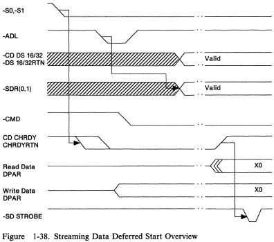
Figure 1-38. Streaming Data Deferred Start Overview
Pacing the Data: After a
16- or 32-bit streaming data cycle is started, CD CHRDY and
CHRDYRTN pace the data transfer, allowing slaves to
introduce momentary pauses in the data transfer. CD CHRDY is
clocked simultaneously with data and makes state transitions
following the high-to-low transition of -SD STROBE On each
falling edge, the controlling master must inspect the state
of CHRDYRTN. When CHRDYRTN is inactive during a read
operation, it indicates that the slave did not have valid
data in this clock period and that the transfer must be
repeated. When CHRDYRTN is inactive during a write
operation, it indicates the slave did not accept the data
and that the transfer must be repeated.
Note: Data pacing by the
slave is not supported during 64-bit streaming data cycles.
An example of data pacing using CD CHRDY is shown in Figure
1-39. The example shows two idle (CD CHRDY inactive) clock
periods, one in the middle of the data transfer, and one at
the end. If the slave has driven CD CHRDY inactive, it must
not deactivate -SDR(0,1).
When -MSDR is active, the slave cannot pace the transfer.
The slave can use CD CHRDY only to delay the initiation of
64-bit transfers. Slaves that cannot meet the timing
specifications for the 64-bit transfer must terminate the
streaming data cycle. After -SD STROBE is being driven, the
master ignores CHRDYRTN.
In this example, as the controlling source of CD CHRDY, the
slave internally clocks its bus interface registers with the
inversion of -SD STROBE. At the end of the cycle, the bus
interface registers are clocked when -CMD goes high. The
internal interface clock of the controlling master is
conditional on CHRDYRTN being active.
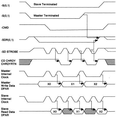
Figure 1-39. CD CHRDY and Data Pacing
To perform data transfer pacing, streaming masters can
introduce momentary pauses in the data transfer by
extending-SD STROBE. Data is transferred on the falling edge
of -SD STROBE. The strobe period can be extended at either
the high or low level, or both. This is done asynchronously
to the edges of -SD STROBE.
Whenever the slave is not-ready (CD CHRDY inactive), the
master must continue to pulse -SD STROBE. The actual data
transfer will occur on the falling edge of -SD STROBE once
the slave becomes ready by driving CD CHRDY active.
Terminating the Cycle:
Either the controlling master or the slave can terminate the
streaming data procedure. If -PREEMPT has become active, the
controlling master terminates the streaming data procedure
within 7.8 microseconds and releases the channel at EOT. If
the fairness feature is active, the preempted master enters
the inactive state. See "Fairness Feature and the Inactive
State" on page 1-26 for more information.
Figure 1-40 shows streaming data cycle termination by the
controlling master.
Figure 1-41 on page 1-55 shows streaming data cycle
termination by the controlling master when the slave is not
ready. Figure 1-42 on page 1-55 shows streaming data cycle
termination by a streaming slave.
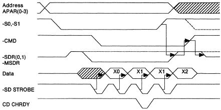
Figure 1-40. Master-Terminated Streaming Data Cycle
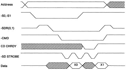
Figure 1-41. Master-Terminated Streaming Data Cycle (Slave Not Ready)
Figure 1-42 shows how a streaming data cycle can be
terminated by a slave. However, if the master has not
transferred all of its data, the master can immediately
initiate an additional data transfer procedure.
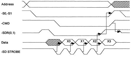
Figure 1-42. Slave-Terminated Streaming Data Cycle
The slave can terminate a streaming data cycle by driving
-SDR(0,1) inactive following
the last desired high-to-low transition of the -SD STROBE.
The slave must not drive -SDR(0,1) inactive while CD CHRDY
is inactive. The controlling master stops -SD STROBE and
deactivates -S0, -S1 and -CMD at the point where the next
-SD STROBE would have been.
A slave that does not drive CD CHRDY inactive (in response
to slave selection) must not drive -SDR(0,1) or -MSDR
inactive with the intention of executing a slave-terminated
single-cycle operation. This ensures that the master has
adequate time to sample the state of -SDR(0,1) before it is
deactivated. The slave must be able to execute two or more
data transfers with the master. The slave can sample TR32 to
determine if two or four bytes will be transferred with each
-SD STROBE. A master can perform a single streaming-data
cycle operation. A master that performs a single
streaming-data cycle must make sure that it meets the basic
timing requirements (T10) as well as all master-terminated
streaming-data requirements, including T71A.
When -CMD is driven inactive, the slave tri-states
-SDR(0,l), -MSDR and, if performing a read operation, the
data bus. The termination sequence results in restoring the
streaming data signals to their inactive state prior to
their being tri-stated, eliminating uncertainties about the
state of these signals in succeeding channel cycles.
Streaming Data Timing
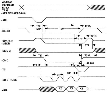
Figure 1-43. Streaming Data Cycle
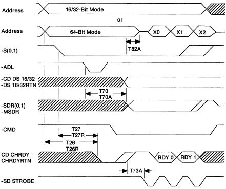
Figure 1-44. Streaming Data Cycle - Deferred Start
Note: CD CHRDY is not
supported during 64-bit streaming data transfers after the
address has been removed.
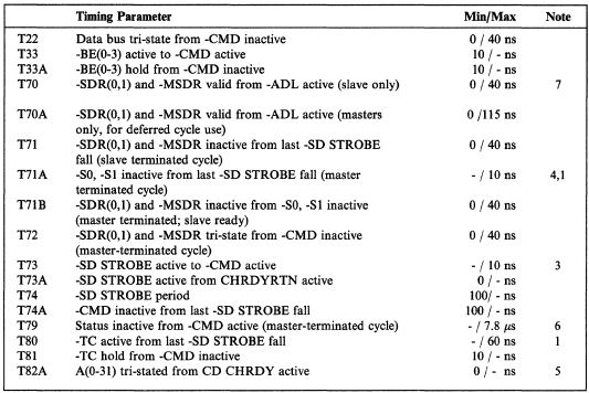
Figure 1-45. Streaming Data Transfer Timing Specifications
Notes:
Streaming masters can increase T71A and T80 by the amount
that the -SD STROBE clock period exceeds T74 minimum. For streaming data cycles that default to the basic
transfer cycles, the rules for deactivation of -S0, -S1
apply, as specified by the basic transfer procedure. -SD STROBE can be driven active concurrently or after
-CMD active, and can become active just before -CMD active
due to driver skew and loading. -S0, -S1 are deactivated concurrently with the negative
transition of -SD STROBE. Normal skew from circuits and net
loading can result in -S0, -S1 being deactivated prior to
the negative transition of -SD STROBE in order to meet the
T71A timing requirement. This timing applies only to the 64-bit streaming data
transfer. The master must signal termination of the streaming data
transfer within 7.8 microseconds from -CMD active. However,
if -PREEMPT goes active, the master can continue to hold the
channel for 7.8 microseconds from-PREEMPT. A valid address decode must be completed before driving
these signals.
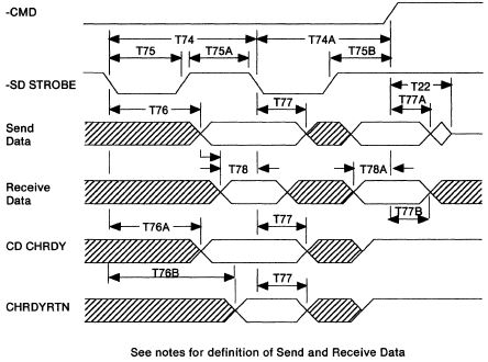
Figure 1-46. Streaming Data Clocking (16- and 32-Bit)
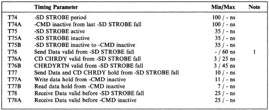
Figure 1-47. Streaming Data Transfer Timing Specifications (16- and 32-Bit)
Notes:
Streaming masters can increase T76 by the amount that the
-SD STROBE clock period exceeds T74 minimum. To perform data transfer pacing, streaming masters can
introduce momentary pauses in the data transfer by extending
the active or inactive levels of the streaming data strobe. Send Data refers to write data at the connector for the
master and read data at the connector for the slave. Receive
Data refers to read data at the connector for the master and
write data at the connector for the slave. The value of (T74 minus T76 minus T78) represents system
timing margins to accommodate bus skew, propagation delays,
and other signal transmission delays.
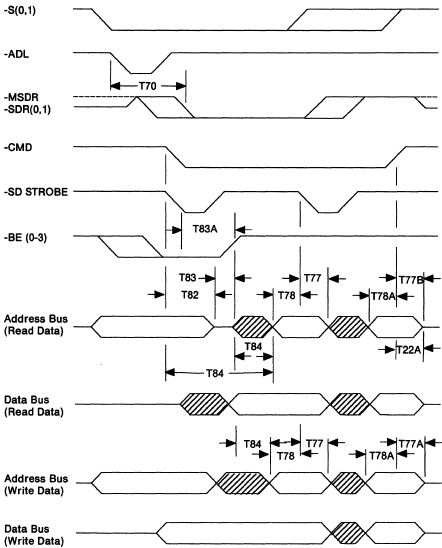
Figure 1-48. Streaming Data Clocking (64-Bit)
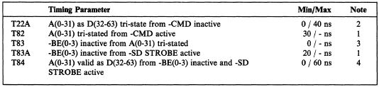
Figure 1-49. Streaming Data Transfer Timing Specifications
(64-Bit)
Notes:
This timing applies only to a master during a read
operation. This timing applies only to a slave during a read
operation. During write operations, the master must meet the setup
and hold times for the 16- and 32-bit streaming data
transfer. Streaming masters can increase T84 by the amount that the
-SD STROBE clock period exceeds T74 minimum.
|