|
Source: Personal Systems Magazine, 1989 Issue 4 (G325-5004-00) (page 70 phys.)
Authors: Frank Bonevento; Ernie Mandese, Joe McGovern and Gene Thomas
The Subsystem Control Block (SCB) architecture was developed
by IBM to standardize the engineering task of designing
Micro Channel bus master programming interfaces as well as
the programming task of supporting them. This article
provides an introduction to the architecture, discusses some
of its underlying concepts, and describes its delivery
service facilities.
The Micro Channel bus master facility provides a structure
for the independent execution of work in a system.
Independent execution of work by bus masters frees a system
unit, for example, to perform other tasks. Doing more work
in parallel typically improves the response time and
throughput of the system as perceived by the end user. The
SCB architecture builds on the Micro Channel bus master
capabilities by defining the services and conventions needed
to design, implement, and use bus masters effectively.
The SCB architecture supports many functions found in larger
IBM systems designed to facilitate multiprocessing. Command
chaining, data chaining, signaling masters, and a
free-running duplex control block delivery service have been
provided. Finally, the ability to support user-defined
control blocks provides a means for dealing with the
requirements of existing, current, and future applications.
Purpose
The SCB architecture provides a programming model for the
Micro Channel and a definition of the logical protocols used
to transfer commands, data, and status information between
bus master feature adapters. The SCB architecture employs
Micro Channel architecture as its underlying physical
transport mechanism. The term "control block" in the
architecture name refers to the organization of the control
information (commands) into areas that are separate from the
data areas. The separation of control and data is used to
increase performance, raise the level of functional
capability, and provide the implementation independence
required by today's applications.
The SCB architecture defines a control block structure for
use between entities in a system unit and entities in
feature adapters that have Micro Channel bus master
capabilities. "Entity" in this context is a collective term
referring to both device drivers and/or resource support
found in a system unit, as well as device interfaces and/or
resources found in feature adapters. The architecture also
defines how control block delivery is provided between
entities in a system unit and a feature adapter, as well as
between entities in feature adapters on the Micro Channel.
The contents of the control blocks have been defined so that
they offer a great deal of functional capability while, at
the same time, providing implementation independence between
the entities in the system unit and the entities in the
feature adapter. This allows entities in a system unit to
offload or distribute work to entities in feature adapters,
thereby freeing them to perform other tasks. It also allows
entities in a feature adapter to optimize their
implementations without concern for entity interactions or
internal implementation details.
The level of interaction between entities of the
architecture is at a logical protocol level in order to
insulate users from the details of, and interactions with,
the underlying implementations. This means that applications
written to adhere to the architecture and the underlying
implementations that conform to it will remain viable even
as technology advances.
Thus, as a feature adapter or system unit is enhanced to
take advantage of new technology (higher data rates on the
Micro Channel, the existence of data and/or address parity
checking, and so on), it will be possible to continue to use
existing applications with little or no change.
Scope
The SCB architecture has been designed to have broad
application and be used in a variety of areas, including the
following:
Traditional I/O Protocols:
Traditional I/O protocols typically have a single system unit that
requests a feature adapter to perform work on its behalf.
This type of feature adapter might be found in an
intelligent file subsystem on a personal system or a
workstation.
For the traditional I/O systems, application of the
architecture would probably mean use of the Locate mode form
of control block delivery. In Locate mode, only the address
of the control block is delivered to the subsystem. The
subsystem uses this address to locate the control block and
to fetch it into its own private storage area for execution.
In these I/O systems, a close synchronization is usually
maintained between the request and the response to the
request.
Peer-to-Peer Protocols:
In peer-to-peer protocols, requests flow not only from the
system unit to feature adapters, but also from feature
adapter to feature adapter without direct involvement of the
system unit. This might be found in feature adapters that
serve as local area network (LAN) bridges or gateways,
providing routing for file servers on LANs. Peer-to-peer
protocols may also be found in loosely coupled
multiprocessing systems.
Communications Protocols:
Communications protocols may require routing to network
servers within a feature adapter and the handling of replies
that arrive out of sequence and are interspersed with
requests. They may also require the ability to handle the
movement of large amounts of data at very high speeds.
Response-Time-Critical
Applications: Response-time-critical
applications require fast response time. The architecture
defines a full-duplex, free-running delivery capability to
support multiple work requests and replies. The amount of
data transferred as well as the speed of the data transfer
are critical in this environment.
In the last three categories, application of the
architecture would probably mean the use of the Move mode
form of control block delivery. In Move mode, control blocks
are moved from the requesting, or client, entity to the
providing, or server, entity using a shared storage area.
This shared storage area behaves like the named pipe
function found in several of today's operating systems.
Delivery using pipes is free-flowing and defined so that
separate pipes exist for both inbound and outbound flows to
and from the server (full duplex operation). This form of
delivery is commonly used by controllers that have very high
arrival rates of work requests and/or run in an asynchronous
manner.
The SCB architecture is intended for use by both IBM and
non-IBM developers designing bus master feature adapters for
the Micro Channel.
Architecture Overview
The following sets forth some basic concepts used in
developing the SCB architecture, its hardware context,
system context, and its service structure.
Concepts
In the personal systems and workstation environments, there
is a need to establish a higher-level, control
block-oriented interface between support operating in a
system unit (system-side entities) and support operating in
a feature adapter (adapter-side entities). There is also a
need for the same higher-level interface between support
operating in two different feature adapters.
The nature of this interface is such that the control block
information and the data can be considered as two separate
parts of the communication between two cooperating entities.
Control block delivery service is used by each entity to
communicate control information. Based upon this control
information, there may also be data to be communicated
between the two entities. This is referred to as "data
delivery."
Additionally, there may be information required during
system initialization to tailor the delivery support to a
particular configuration. This is configuration information.
Figure 1 gives an overview of the control block, data, and
configuration delivery support.

Figure 1. Overview of Delivery Support
Capabilities
Understanding the SCB architecture starts with understanding
the requirements that are common to designers of Micro
Channel bus master hardware and engineering software. From
these requirements, the capabilities of a bus master feature
adapter can be identified. The following are some of the
most commonly requested capabilities.
Provide a Programming Model for the Micro Channel:
- Provide flexibility
- Support function distribution
- Support signaling among all bus masters and their users
- Provide a higher functional level of interface
- Support command chaining
- Support data chaining
- Provide request / reply protocol between users
- Provide means of correlating requests to replies
- Provide source and destination identification
- Allow multiple outstanding requests
- Allow unsolicited operations
- Allow data to be carried within control blocks
Support Bus Masters on the Micro Channel:
- Provide a processor-independent architecture
- Provide full duplex operation
- Support feature adapter-to-feature adapter operation (peer-to-peer)
- Support asynchronous operations
Improve Performance and Throughput:
- Reduce interrupt overhead
- Support expedited requests
Hardware Context
To better understand the structure of control blocks and the
overall structure of the control block delivery service, it
may be helpful to provide an example of the hardware within
which the delivery service is expected to operate.
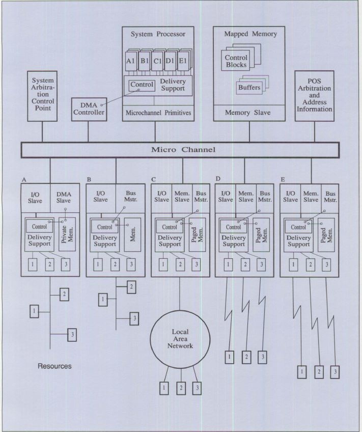
Figure 2. Hardware Environment
Figure 2 is an example of a hardware configuration that
would benefit from using control blocks and the control
block delivery service. This example shows several types of
bus master feature adapters present on the Micro Channel,
each using the bus master capabilities of the Micro Channel,
and each providing support for one or more resources or
devices. The example shows that there are multiple types of
I/O system support within the system unit, each providing
access to and support for resources and/or devices
associated with a particular subsystem and feature adapter.
The functions available on bus master feature adapters are
also used to establish peer-to-peer relationships between
feature adapters, as well as between system units and
feature adapters.
System Context
It is helpful to have an example that shows where control
blocks and control block delivery fit relative to a system
unit or feature adapter operating environment. This can
easily be done for a system unit, but is much more difficult
to do for the many different types of feature adapters. This
is due to the nature of feature adapter implementations. At
the low end, the operating environment may consist of
nothing more than hardware logic and state machines. At the
high end, it may consist of a powerful microprocessor with
paged memory and a multitasking kernel or operating system.
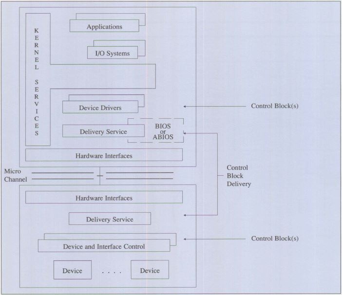
Figure 3. Example of System Unit Operating Environment
Figure 3 is an example of how the delivery service maps into
a system unit in a DOS or OS/2 type of operating
environment.
Service Structure
The control block delivery service may be viewed as
supporting communications between client entities located in
the system unit and server entities located in a feature
adapter. The delivery service itself is distributed between
the system unit and the feature adapter. The portion of the
delivery service local to each is the local delivery agent.
Delivery agents communicate with each other using the
services provided by the Micro Channel. Micro Channel
services include memory and I/O space that is shared between
the system unit and the feature adapter. This view of the
delivery service is shown in Figure 4.
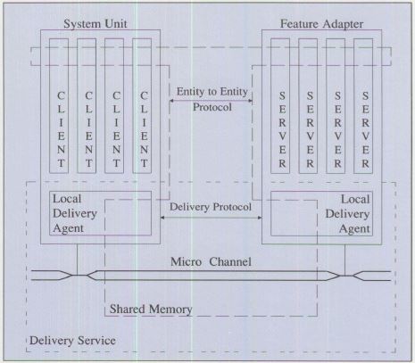
Figure 4. Generic Delivery Service
The delivery service supports the delivery of control blocks
between pairs of entities (a client and a server). These
entities build and interpret the control blocks. The actual
control blocks, their content, and their sequence determines
the specific entity-to-entity protocol being used between a
client and server.
Both the control block delivery protocol and the
entity-to-entity protocol(s) may use the shared memory to
physically pass control information and data between the
system unit and feature adapters.
The internal operation and distribution of the delivery
service is logically structured into a delivery layer and a
physical layer. The delivery layer supports the delivery of
control blocks between "entity" pairs. The physical layer
supports the delivery protocols used between "unit" pairs
(delivery agents). The definition for the delivery protocol
is based upon a Micro Channel form of physical connectivity
between system units and/or feature adapters.
Users of the delivery service (entities representing clients
and/or servers) are the next higher layer of service.
Understanding the overall operation of the entity-to-entity
layer services was key to defining the services to be
provided by the underlying delivery service and the
protocols needed to support the distribution of these
services among the system units and feature adapters.
This layered structure for delivery services is shown in
Figure 5.

Figure 5. Delivery Service Structure
This layering of delivery services allows the various
entity-to-entity protocols to share a common delivery
service. The delivery protocol can be full-duplex and
free-running while individual entity-to-entity protocols may
be half-duplex and of the master/ slave form . The delivery
protocol allows the delivery support to be mapped onto the
different forms of the physical level protocols that must be
used with different unit-to-unit pairings; that is, system
unit-to-feature adapter, feature adapter-to-system unit, and
feature adapter-to-feature adapter.
Delivery Service Facilities
The delivery service facility provides two operational
modes: Locate mode and Move mode. The following describes
the services, functions, and protocols provided by each and
a brief description of the underlying control structures.
Locate Mode Support
The Locate mode form of control block delivery supports a
control structure that has a relatively fixed control block
structure. The control blocks are delivered to the server
one control block at a time. The Locate mode control block
delivery structure is shown in Figure 6. Locate mode control
block delivery provides:
Multiple Devices per Adapter:
Subsystems will generally provide support for multiple
devices and/or resources. These may be small computer system
interface (SCSI) devices, LAN connections, X.25 virtual
circuits, integrated-services digital network (ISDN)
channels, communications lines, or processes. The delivery
mechanism supports the delivery of requests to specific
devices and/or resources through the use of device
identification numbers (for example, Device 1, Device 2,
Device n).
Subsystem Management:
There is a requirement to deliver subsystem management
information as well as control information to the subsystem.
The subsystem manager is assigned Device identification
number 0 and receives all subsystem management information.
Requests to Devices: To
use a device or resource, a program (the client) sends
requests in the form of control blocks to a specific device
or resource (the server) and receives replies from the
device or resource for those requests. A single program or
multiple programs operating in a system unit can be using a
device or resource in a subsystem. These programs may be
using the same or different devices or resources in the
subsystem.
Command and Data Chaining and
Detailed Status: The control structure
defined for Locate mode provides for an immediate request, a
request made up of multiple control blocks chained in a
specific order and treated as one logical request, or using
an Indirect List for chaining multiple buffers associated
with a given control block.
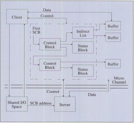
Figure 6. Locate Mode Control Block Delivery Structure
Figure 6 shows a sample control request structure that
consists of two control blocks (command chaining). The first
control block uses an Indirect List to reference multiple
buffers (data chaining). The other has a single buffer. The
commands and parameters are contained within the individual
control blocks.
The structure also provides for handling status information
in case of exceptions during the processing of a request.
The status is placed in a Termination Status Block. In order
to handle termination at any point in a chain, a Termination
Status Block is associated with each control block in the
chain.
Use of Direct Memory Access (DMA):
The Locate mode form of delivery defines the interfaces to
support the case where both the control structure for a
request and the data associated with a control block are
transferred between the system unit and the feature adapter
using DMA operations managed from the subsystem.
Interrupts: The delivery
service allows the builder of a request structure to define
when and under what conditions interrupts should be
generated. Generally there will be one interrupt per
request. This will occur at the end of the request for
exception-free operation. Additional interrupts may be
requested in any control block in order to synchronize
activities. Explicit commands are used to reset device
interrupts.
The flow of the interrupt processing is from the hardware to
the operating system kernel to the device driver (interrupt
portion) and, when ABIOS is used, to the Advanced Basic
Input/ Output System (ABIOS) interrupt entry point. The
interrupt processing uses information provided as part of
the request/reply interface to determine which of the
devices or resources in the subsystem caused the interrupt.
Locate Mode Control Areas
The architecture identifies the specific control areas in
I/O space to be used, as well as the protocols for
initializing and using a feature adapter in Locate mode.
Because multiple feature adapters of the same, or different
types may be used in the system, the base address for the
I/O space of each feature adapter must be defined during
setup. The I/O control areas used by a feature adapter are
shown in Figure 7 as offsets from the I/O base address.

Figure 7. I/O Control Areas
In the following descriptions, the term "port" refers to a
byte or set of contiguous bytes in the system.
Request Ports: There are
four types of request ports associated with sending requests
to a resource or device in Locate mode. The first, the
Command Interface Port, is used to pass either the 32-bit
address of a control block or the first control block in a
chain to a subsystem in a feature adapter. It is also used
to pass immediate commands. These immediate commands are
typically device-directed and control-oriented.
The second is the Attention Port. It contains an attention
code and a device identifier. The attention code is used to
inform the subsystem in the feature adapter that the Command
Interface Port contains either the address of a control
block or an immediate command. The device identifier
indicates which device or resource on the subsystem the
request is directed to.
The sequence of sending a request involves writing to the
Command and Attention Ports in that order.
The third, the Interrupt Status Port, is used when the
subsystem has completed processing a request or immediate
command. It provides information needed by the system unit
to associate a Micro Channel interrupt with a specific
device on the subsystem. In addition to identifying the
interrupting device, it also indicates whether or not an
exception condition exists.
The fourth is the Command Busy/Status Port. It is used by
the subsystem in a feature adapter to serialize access to
the shared logic of the control block delivery service, the
subsystem, or the device/resource. The port contains the
following indicators:
- Busy - indicates that the subsystem is busy (using the
shared logic). Commands submitted while Busy are ignored by
the subsystem in the feature adapter.
- Interrupt Valid - indicates that the contents of the
Interrupt Status Port are valid and that the subsystem has
requested an interrupt on behalf of one of its devices or
resources.
- Reject - indicates that the subsystem has rejected a
request (a Reset is needed to clear a Reject and allow the
subsystem to resume accepting requests).
- Status - indicates the reason for the rejection.
Subsystem Control Port:
The Subsystem Control Port is used to pass control
indicators directly to a subsystem that cannot be easily
handled by requests to subsystem management. The port
contains the following control indicators:
- Enable Interrupts - indicates that interrupts should be
enabled or disabled for all devices attached to the
subsystem in the feature adapter.
- Enable DMA - indicates that DMA operations should be
enabled or disabled.
- Reset Reject - indicates that a reset of the reject state
of the subsystem should be performed.
- Reset - indicates that a reset of the subsystem and all
devices in the subsystem should be performed.
Device Interrupt Identifier Ports:
Interrupt status for all devices and resources associated
with a subsystem are reported to the system unit through the
Interrupt Status Port. However, when the optional Device
Interrupt Identifier Port(s) are used, only the interrupt
status for immediate commands will be reported through the
Interrupt Status Port. All other interrupts will be reported
using the Device Interrupt Status Port(s). When a device or
resource completes processing a control block, it sets the
bit in the Device Interrupt Identifier Port corresponding to
its device or resource identifier, and then interrupts the
system unit.
By using these optional ports, an interrupt handling program
can process multiple control block interrupts on a single
Micro Channel physical interrupt. This is accomplished by
reading the Device Interrupt Identifier Port(s), and using
the special immediate command, Reset Subsystem Control Block
Interrupts, to clear the interrupt requests for the device.
Before issuing requests, the system unit software must
ensure that the subsystem is enabled to accept new requests,
that is, not Busy or in the Reject state. If virtual memory
is being used, the system-unit software must ensure that all
control blocks, Termination Status Blocks, Indirect Lists,
and data areas associated with a request are locked into
memory.
Control Blocks
The structure and content of a typical control block is
shown in Figure 8.
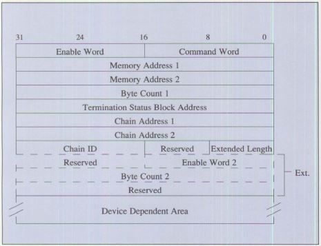
Figure 8. Control Block Format
There are two formats for the control block: basic and
extended. Both forms share all of the fields shown in solid
lines. The remaining fields (shown in dashed lines) are
present only in the Extended Format. The Device Dependent
Area is also present in both forms. However, the actual
location of the area within the control block is dependent
upon whether the basic or the extended form is used.
The physical address of the control block must be placed in
the Command Interface Port and the device address and
attention code in the Attention Port, in that order.
Indirect Lists
An Indirect List is a variable-length list consisting of
address-count pairs used to support data chaining. Both the
address and the count are four bytes. The length of the list
is contained in the control block that points to the list.
The format of the Indirect List is shown in Figure 9.
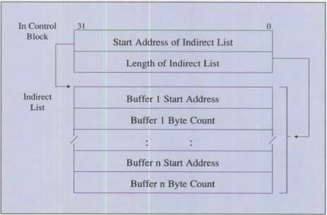
Figure 9. Indirect List Format
Termination Status Blocks
In addition to the exception/no exception indication in the
Interrupt Status Port, the SCB architecture provides for
detail status information to be reported for each command.
The status information is reported in the Termination Status
Block (TSB). Each control block includes a TSB address to
which a subsystem writes completion or termination status
for that control block. The format of the basic TSB is shown
in Figure 10.

Figure 10. Termination Status Block Format
Move Mode Support
The Move mode form of the control block delivery supports a
control structure designed to allow a variable-length list
of control-element primitives to be used to deliver control
information to a server. This variable-length list may
contain requests, replies, error, or event notifications for
a specific device or resource in a subsystem, or for
different devices or resources in the same subsystem.
The Move mode control block delivery structure in Figure 11
shows the interface to the delivery support and the various
memory spaces related to control element delivery.
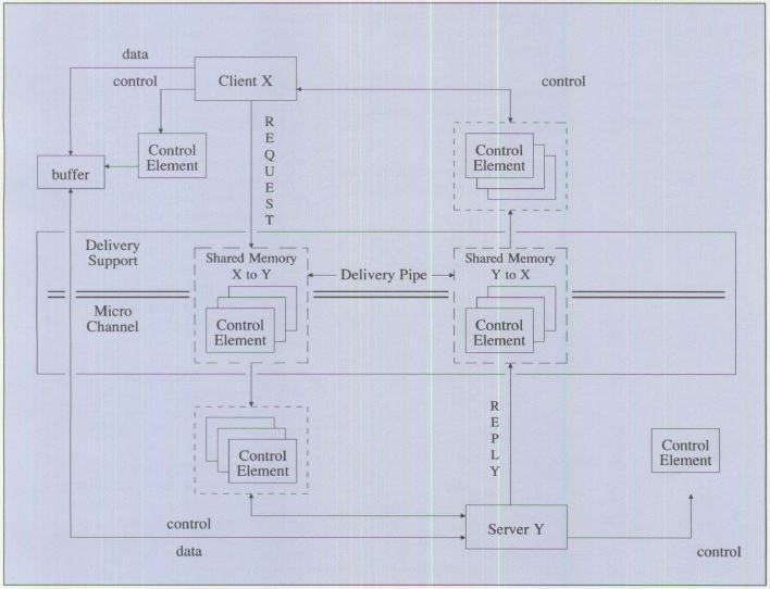
Figure 11. Move Mode Control Block Delivery Structure
The Move mode facility has an overall structure similar to
that of the Locate mode facility; that is, clients build
requests, requests are delivered to server, server builds
replies, and replies are delivered to client. There are a
number of additional capabilities that have been defined for
the Move mode delivery facility.
The following are the additional Move mode capabilities.
Request/Reply Extensions:
Request/reply extensions define support for error and event
control elements in addition to request and reply control
elements and the ability to have multiple outstanding
requests between entity pairs. The flow of control elements
is independent of the physical layer protocols. The two
parties in a specific entity pair have been defined as the
client and the server. In general, the client sends requests
to a server and the server sends replies back to that
client. Events may flow in either direction. The delivery
mechanism supports the delivery of these requests, replies,
errors, and events among source and destinations having
multiple client server pair relationships.
Shared Memory: Shared
memory allows for the use of memory in feature adapters as
well as memory in the system unit. This allows the control
structure used to convey control elements to be located in
either the system unit or the feature adapter. It also
allows for various options when determining how the control
structure is built and moved to the destination entity. (The
server is the destination entity for requests and the client
is the destination entity for replies.)
Figure 4 depicts the fact that memory is shared between the
units and feature adapters. How this memory is shared and
accessed will be different for different system environments
(move/copy, DMA, and so on). The definition of the Move mode
control structure provides for the fact that different forms
of memory addressing will be needed.
Variable-Length Requests and
Replies: The Move mode support provides a
control structure that allows a request to be made up of a
set of variable-length control elements. At the entity
interface, these elements are contiguous. This allows for
chaining of control elements within a request to be done
with a minimum of address manipulation. It also allows for a
minimum-size control block for passing simple requests and
replies.
Variable-length control elements addresses the need to have
smaller control structures, to be able to pass a variable
number of request parameters and to have a simple way to
support a number of different subsets. Some client/ server
entity pairs may choose to use complex combinations of
primitives while others use a simple set. They are all
implemented from the same set of primitives using the same
delivery services.
Lists of Requests and Replies:
Figure 11 shows a sample set of control elements flowing
from a client to a server and another flowing from a server
to a client; both flow on the shared memory delivery service
pipes.
The delivery pipes defined for the Move mode control element
delivery service have the following attributes:
Full duplex
A pipe for each direction of delivery between units. This
allows for the delivery of control elements in one direction
independent of the delivery of control elements in the other
direction.
The control structure provides correlation between requests
and replies. Multiplexing of entity pairs
Each pipe may
have control elements for multiple entity pairs in the same
pipe. The control structure provides for source and
destination identification in the control elements to allow
a set of control elements for different entity pairs to be
delivered in the same pipe. Intermixing of requests and replies
The control structure supports a
mixture of request and reply as well as other control
element types in the same pipe. Continuously running
The control structure permits the delivery of control
elements in a continuous flow. Mechanisms are defined to
provide a common way for entities to suspend the delivery of
control elements at the entity-to-entity level, to notify
the destination entity that a control element(s) is
available and to provide for synchronization between the
entities in the source and the destination.
Move Mode Control Areas
The architecture identifies the specific control areas in
I/O space to be used as well as the protocols for
initializing and using a feature adapter in Move mode. The
control areas are essentially the same as those used for
Locate mode, except the Command Interface Port, Interrupt
Status Port, and Device Interrupt Identifier Ports are not
used.
Because multiple feature adapters of the same or different
types may be used in the system, the base address for the
I/O space of each feature adapter must be defined during
setup. The I/O control areas used by a feature adapter are
shown in Figure 7 as offsets from the I/O base address.
Control Elements
Control elements are like control blocks. They are used to
exchange control information between a client and a server.
However, control elements differ from control blocks in the
following ways:
- Control elements are variable in length.
- Control elements are self-describing.
- Control elements provide a means of specifying the
destination, identifying the source, and indicating the type
and urgency of the control information they contain.
- Control elements may optionally contain data as well as
control information.
- Control elements contain information for correlating
requests with replies.
- Control elements may be processed asynchronously.
To draw an analogy, a control element is like an envelope
with a see-through window, while a control block is more
like a post card. Both have a purpose and a use.
Delivery services use information in the window to deliver
control elements, without knowing or understanding what is
contained within the body of the control element.
Clients and servers use information in the window to specify
the destination, identify the source, indicate the type and
urgency of the control information, and correlate replies
with previous requests.
Figure 12 shows the format of a typical control element.
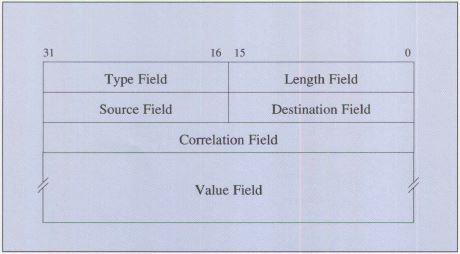
Figure 12. Control Element Format
The type, length, source, destination, and correlation
fields are used by the delivery service as well as the
client and server. They constitute the information visible
through the window in the envelope. The remaining
variable-length field, the value field, represents the
contents of the envelope (that is, the control information).
The structure, content, and length of this field is
determined by the particular protocol being used between a
client and server and is meaningful only to them.
Queueing Control Elements
With the use of delivery pipes in Move mode (which are
implemented as circular queues), there is a tendency to want
to mix the queuing capability defined to support the
delivery of control elements between units and the queuing
of control elements to a specific server. Figure 13 shows a
request flow example of a delivery pipe as defined by SCB
architecture. The delivery protocols support a freeflowing
pipe between entities. Each entity pair is responsible for
ensuring that there is a pending receive for elements sent
so that one entity cannot block others from using the pipe.
If there is no pending receive, the delivery service can
discard the element and notify the source entity (sender of
the element).
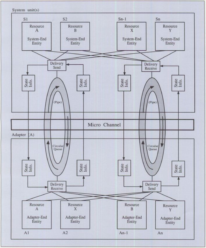
Figure 13. Handling Control Elements in Move Mode
Entity-to-Entity Relationships
For the Move mode form of control block delivery, the
generic configuration shown in Figure 4 must to be expanded
to include both system unit-to-feature adapter and feature
adapter-to-feature adapter delivery. The feature
adapter-to-feature adapter operations are referred to as
"peer-to-peer."
Peer-to-Peer Relationships
From a delivery point of view, the term "peer-to-peer"
implies that there are no restrictions about where clients
and servers may be located. It does not say anything about
the relationship between the various client and server
entities (which may be operating in a non-peer
relationship). It also refers to the fact that control
elements may be delivered directly between any two system
unit and/or feature adapter that are physically connected by
the Micro Channel.
In order to operate in a peer-to-peer relationship, the
delivery support must allow requests and replies to flow in
either direction and to be mixed on the same delivery-level
flow. In the Move mode form of control element delivery,
this is supported by having independent delivery of control
elements in either direction and by allowing clients in
system units or feature adapters and servers in feature
adapters or system units. Peer-to-peer also requires support
in both system and feature adapters to resolve contention
when two or more system units or feature adapters attempt to
deliver control elements to the same destination at the same
time.
The term "peer-to-peer" must be qualified by the level of
support being discussed and not used as a unit-to-unit term
without qualification.
Peer-to-peer delivery support has a pair of delivery pipes
for each unit-to-unit pair with entities that communicate
with each other. An example of this is shown in Figure 14.
The labels R1, R2, and so on, on the client/ server
entities indicate the entity pairings. The dotted areas
indicate the delivery support portion in each unit.

Figure 14. Peer-to-Peer Delivery Model
Figure 14 shows each delivery pipe as being distributed to
both the source and destination. The definitions for the
Move mode form of control block delivery are for cases where
the actual physical queues implementing the pipes are in
either the source or the destination, but not both.
Management Services
In addition to the peer-to-peer control element support,
there is also a requirement to have a management structure
to allow for the handling of various management services
related to the operation of the delivery services.
The SCB architecture requires an entity in each system unit
or feature adapter to be used for management support. This
management entity, which is shared by all the other
entities, has an entity identifier of zero. The management
entity structure is shown in Figure 15.
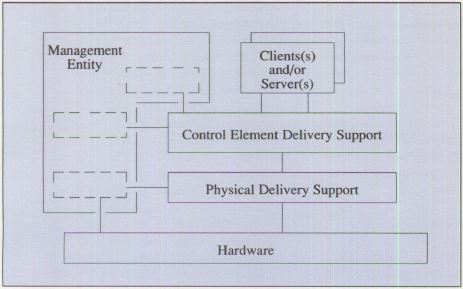
Figure 15. Delivery Management Services
These management entities may use the delivery services to
send control elements to or receive control elements from a
system-level management entity. The system management
entity, which does not have an entity ID of zero, provides
system-wide management services (Figure 16).
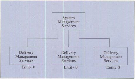
Figure 16. System Management Services Structure
This management structure may support management services of
various types and is not unique to the delivery service.
This means that it could be used for entity layer reporting
and testing as well as delivery layer(s) management.
The management structure represents a unique form of client
server support. The management services for a system are
hierarchical even though the delivery support for clients
and servers is peer-to-peer. This is an example of the fact
that the basic delivery relationship is separate from the
entity-to-entity relationship.
Summary
The SCB architecture was developed to standardize the
programming task of supporting Micro Channel bus master
feature adapters, as well as the engineering task of
designing the bus master programming interface. It gives the
adapter designer the freedom to define the meaning and
content of the protocols that the feature adapter supports,
while at the same time providing the programs using these
feature adapters with standards for important interfaces.
See also SCB Architecture (pdf)
|