|
Author: Trevor Marshall
Source: March 1992 BYTE, Pages 131-134, 136, 138
IBM has taught us that compatibility is the single most important attribute
for a mass-market bus. Without compatibility, there is no incentive to produce
the innovative, third-party peripherals that have largely determined what we
can expect for today's personal computers.
The second most significant characteristic is speed. The bus must be fast
enough to transfer data from modern high speed peripherals to the host CPU with
no noticeable degradation in system performance.
The original IBM XT was shipped with a very limited 8-bit expansion bus. It
was not long before add-in cards started to tax its capabilities, so, with the
release of the IBM AT, this 8-bit bus was widened to 16 bits and increased
functionality was added. This created a clumsy (but standard) protocol now
dubbed Industry Standard Architecture (ISA).
Four years ago, IBM announced with great fanfare that it had created the
most advanced bus a desktop computer would ever need. It was called the Micro
Channel. Soon after, a consortium of IBM competitors announced its own
"perfect" bus, dubbed EISA (for Extended ISA). Both of these buses were claimed
to be extensible, to have much higher performance than ISA, and to be its
obvious successor.
Yet despite the Claims (and hopes) of both EISA and Micro Channel promoters,
neither architecture has managed to take a significant share of the market.
Less than 5 percent of PC compatible machines sold worldwide use the EISA bus.
The remainder are mostly still ISA (AT-bus) compatibles. The Micro Channel has
made an impact, but primarily in applications where bus speed is not a factor,
such as point-of-sale terminals and data-entry stations. Consequently, the
volume of Micro Channel add-in boards sold is still small.
Mastering the Buses
The XT bus was designed to complement a 4.77-MHz 8088 processor. It did that
job well, delivering adequate transfer speeds for the add-in adapters of that
day.
By the time the AT was released, it was becoming evident that microcomputers
were soon going to catch up with the performance of the minicomputers and
mainframes that still dominated computing. Consequently, the designers of the
AT enhanced the XT bus by adding more DMA channels, more interrupts, and, most
important, a 1 6-bit data bus. And they did this while retaining downward
compatibility with the XT bus.
The AT bus proved adequate for the types of add-in adapters needed to
complement the performance of an AT -class machine. The bus structure was
reverse-engineered, multisourced, and dubbed the ISA bus.
Both the Micro Channel and EISA designers sought to overcome some of the
limitations remaining in the ISA design. First, they provided a 32-bit data
path to match the newly emerging 32-bit processors, such as the 386 and 486.
Second, they paid a lot of attention to increasing the data transfer rates by
more tightly specifying the bus transfer protocols. Third, they gave both buses
considerable capability to support multiple bus masters.
A bus master is another, usually peripheral, processor that plugs into the
bus yet can access the host processor' s memory and usually all the system
peripherals as well .You need bus-master capability if your system is going to
support intelligent drive controllers, such as those used in high-end network
servers. It is also useful in many industrial applications, such as image
grabbing and image processing.
The ISA bus can only support bus masters if they are set up as DMA
controllers. This limits the data throughput to around 1.5 MBps. In addition,
the host CPU is usually halted during any bus-master transaction.
A bus master should be able to, for example, transfer data from another
peripheral card without affecting the control program running on the host CPU.
EISA and Micro Channel both permit such concurrent processing; ISA does
not.
Speed Limits on Buses
The speed of light limits how fast signals can propagate down a bus
structure. But today's buses operate nowhere near this fundamental limit, do
they? On the contrary.
An electrical signal travels down a perfect bus at about 7.86 inches per
nanosecond. A 33-MHz CPU executes instructions as fast as one every 30 ns.
Thus, if this CPU sent out a request on a perfect bus to a perfect pe1ipheral,
you would lose one complete computational cycle for every 20 feet the signal
had to travel. Naturally; in our imperfect world, things are much worse. To
comprehend the fundamental performance limits for buses, you need to understand
something about transmission-line theory (see the text box "Signals on the
Wire" on page 132).
Signals on the Wire
A transmission line is a wire down which a signal from the CPU propagates to
a peripheral. The simplest case, where only resistive terminating elements
exist, is shown in figure A (see reference 1).
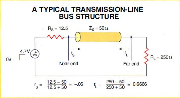
Figure A: A Typical Transmission-Line Bus Structure
Figure A: The electrical model of what seems like a simple line of copper
on a circuit board. The input signal (in this case, a typical 0- to 4. 7-V
logic transition) is modeled as the voltage source (Vs) for the
transmission line. It must drive not only the relatively docile loads of pure
resistance ( RS, the source resistance, and RL the load
resistance) but also the more difficult reactive components Z0
(characteristic impedance of the transmission line), rL (normalized
impedance of the load), and rs, (normalized source impedance).
A 5-volt source with a series damping resistance of Z0/4 ohms
(Z0 is the characteristic impedance, typical of most printed circuit
board conductors) feeds the bus wiring. A typical Z0 on a printed
circuit board is 50 to 150 ohms (see reference 2). The peripheral terminates
the bus with an effective resistance of 5 x Z0 ohms.
Due to the loss in these resistances, only 4.7 V of the 5-V TTL high level
that the CPU generates will be available to drive the peripheral. Because of
signal reflection, you can't decrease the series resistance to transfer more
energy along the bus.
Consider an 8-inch bus. When the CPU's signal reaches its far end, some of
the energy is reflected to the source, giving rise to a theoretical waveform
(see figure B).
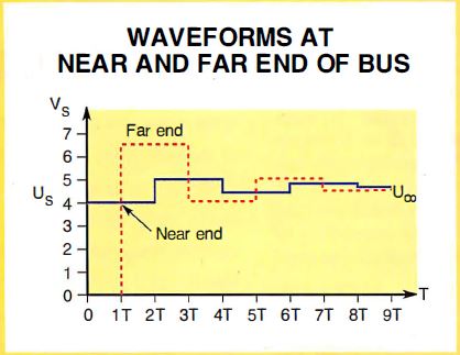
Figure B: Waveforms At Near And Far End Of Bus
Figure B: A logic transition occurs at the near end of a bus at time 0 and
arrives at the far end at 1T, with significant overshoot. The overshoot
propagates back to the near end and changes the voltage there. The reflections
travel up and down, decreasing, until at 8T the bus settles near its final
logic level.
The voltage on the bus oscillates around the final value. If the oscillation
grows too great, it exceeds the threshold value at which a logic device (e.g.,
a bus receiver) is triggered to change state. The receiver may then change its
output value based on a false input generated by circuit ringing. Usually, the
circuitry will fail to work properly, but sometimes the system can read the
false value as a valid bit. In the real world, there is capacitance, not just
pure resistance, to drive.
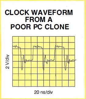
Figure C: Clock Waveform From A Poor PC Clone
Figure C: This oscillograph is taken from an early ISA clone. It shows the
system clock (pin AXX) measured at the end of the bus and severe overshoot.
Figure C is an early ISA clone's system clock (pin AXX) measured at the end
of the bus. The signal badly overshoots the 0-V level and, in fact, reaches a
negative voltage of about -3 V. Then the signal "rings" back t o a level of
about 0.8 V, causing most logic gates to malfunction.
On the positive transition, almost no overshoot occurs, although the peak
voltage is only 3 V-much less than the theoretical 5-V maximum. The difference
is due to an asymmetrical driving impedance.
The designer of the bus in figure C mistakenly used a very fast buffer
device (a 74F245) to drive the clock resistor. The output impedance of this
buffer (which should be greater than Z0/2 to control overshoot) is
extremely low when the signal goes from high to low (the pull down cycle) but
fairly high when the signal goes from low to high (the pull up cycle).
If a slower logic gate had been used, the designer would have achieved
faster system operation overall, less overshoot would have occurred, and the
final voltage would have been achieved more quickly. This is what happens on
the positive side, which is only half as fast as the negative. On the negative
side, the signal achieves the steady-state level almost instantaneously.
The oscilloscope time base was set for one horizontal division every 20
nanoseconds with the CPU speed at 50 MHz. So, here is a bus where one handshake
transaction would make a modern CPU wait almost a full cycle for it to
complete. ISA, Micro Channel, and EISA buses require at least three
transactions in every bus transfer cycle.
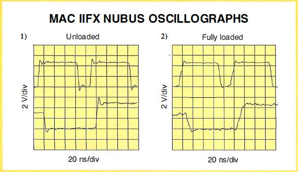
Figure D: Mac IIfx NuBus Oscillographs
Figure D:
(1) An oscillograph taken at the far end of a Mac IIfx NuBus, with
just two cards (the test card and the video card) plugged in. A small amount of
overshoot is present, but not enough to cause logic to malfunction. The rise
and fall times of the signals are quite fast, and the ultimate signal levels
are very close to 0 and 5 V.
(2) Another measurement from the far end of a Mac IIfx NuBus but this
time every slot on the bus has been filled. The rise and fall times have now
been reduced by the extra loading of the four additional peripheral cards, and
the overshoot and settling are insignificant compared to the transition times.
This performance is typical of a bus designed using the best technology
available today.
In an optimally designed system, these transactions occur much faster.
Parts 1 and 2 of Figure D are taken from a Mac IIfx NuBus. Part l was
taken at the far end of the bus, with two cards (the test card and a video
card) plugged in. A little overshoot exists, but not enough to cause logic to
malfunction. The rise and fall times of the signals are fast, and the ultimate
signal levels are close to 0 and 5 V. The two signals shown are the system
clock and start.
Part 2 was taken under the same conditions, but this time with every bus
slot filled. The extra loading that the four additional peripheral cards impose
has reduced the rise and fall times, and the overshoot and settling are
insignificant compared to transition times. This performance is typical of a
bus designed using today's best technology.
So, the fastest time in which a transaction can occur seems to be 10 ns; 20
ns would be safe. So you can expect an ISA, EISA, or Micro Channel bus to
manage one transaction every 30 to 60 ns using interface chips like the
IIfx's. Thus, even the fastest bus transaction will take between one and
two instruction cycles on a 33-MHz CPU.
Editor's note: All oscillographs reproduced here are 20 ns per division
horizontally and 2 V per division vertically. Equipment used for testing bus
signals was as follows: oscilloscope- 500-megasample-per-second Fluke digital
scope; probes- 100x resistive probes, 1500-MHz bandwidth, Philips PM8912.
REFERENCES
1. Arabi, Tarif. National Semiconductor Application Note 707.
2. Jordan, Edward, ed. Reference Data for Engineers: Radio, Electronics,
Computer, and Communications, 5th ed., pp. 22-25. Indianapolis:
Howard Sams, 1985.
Since bus physics fundamentally limits bus speed, the only easy way to
improve the data transfer speed is to increase the width of the data bus (i.e.,
the number of data bits that can be exchanged for each set of bus transactions)
or decrease its length. With today's driver technology, a 32-bit bus can
achieve a data rate of about 60 MBps, a 16-bit bus can reach about 30 MBps, and
an 8-bit bus can attain about 15 MBps.
The PCXI Consortium has been formed to define a variant of the EISA bus that
is better able to serve the needs of scientific, engineering, industrial, and
other power users. It has extra undefined pins capable of carrying signals
between cards on high-speed local buses. These pins can also be used to carry
Data Translation's (Marlborough, MA) DT-Connect bus architecture. The
DT-Connect bus can transfer data at a rate of 100 MBps using standard 74FCT
bus-driver ICs.
Bursts and Streams
To reduce the number of signal transactions needed per data transfer, you
would use so-called burst or streaming data modes. The data rates that the
Micro Channel and EISA promoters quote, 40 MBps and 33 MBps respectively, are
possible only with data streaming.
The problem is that for data streaming, the data needs to be of a continuous
nature. Data from a drive controller is often continuous. But the speed of data
being sent to a video card is more likely to be determined by CPU processing
speed, and the data's transfer is usually performed in the slower
single-transaction modes.
For example, a typical 8-bit ISA bus achieves a data rate of only about 1
MBps in practice- 10 percent of the theoretical maximum. Its primary
limitations are the response time of the cards in the bus and the nature of the
motherboard logic, which uses wait states to slow down the bus to synchronize
with its own internal response times. These limitations apply equally to wider
buses and to EISA and Micro Channel implementations.
I recently checked the relative speeds of a 16-bit Ethernet adapter card and
an 8-bit version of the same product. The 16-bit card provided only a 20
percent performance improvement. You don't need to use an advanced EISA system
when the primary limitations are still processor- and network-related.
The Compatibility Factor
Compatibility among the ISA, EISA, and Micro Channel systems implies, at
least, that software designed to run on ISA machines will run the same way on
EISA and Micro Channel systems. By and large, this has proved to be true.
In addition, compatibility implies that you can expect hardware designed for
the Micro Channel to run in any Micro Channel machine and, similarly,
EISA-designed hardware should run in any EISA machine. EISA promoters also
claim that ISA adapter cards will run in an EISA machine (see the text box
"Compatible May Not Mean Easy").
Compatible May Not Mean Easy
I recently tried to install one of the new low-cost fax-modem cards into a
Hewlett-Packard 486 EISA-based computer. The EISA bus is compatible with ISA,
right? So you just plug in the ISA card and it should work, right? Wrong.
I plugged in the fax card and installed the BitFax software as described in
the manual. When I ran the program, it informed me that no fax card was
present.
A check of the manual showed that all the DIP switches were set correctly
for COM3, so there shouldn't have been any clash with the hardware already
installed in the computer. Then inspiration struck me. I remembered seeing a
press release about EISA doing away with the need for "complex" DIP switches
and replacing them with a setup program. Referring to the HP manual confirmed
that the EISA machine would not recognize the ISA add-in card until it had been
"installed" and that I would need an Adapter Configuration File from the
add-in's manufacturer before the EISA bus could recognize the fax card.
I borrowed a copy of the EISA Programmers Reference Manual from HP and, over
the course of an hour or so, learned yet another programming language, wrote
the Adapter Configuration File, and got the fax card up and running. A call to
HP technical support later revealed that HP could send me a file containing a
set of common adapter descriptions. If a card is sufficiently similar to a
"common" adapter, then that file would have worked.
But why? Why couldn't I just plug the card in and have it work?
From day 1 of the IBM announcements, I had fully understood the proprietary
nature of the Micro Channel bus. It was obvious that if I chose to go the Micro
Channel path to higher performance, I would have to buy specialized adapter
cards, there would be fewer sources for them, and they would be more expensive.
But I never anticipated that EISA would have similar barriers to the
free-market economics that have made personal computer technology such a
success.
Luckily, now that third-party (clone) vendors are starting to ship EISA
machines, software has been written to ease the installation task. Most clones
now ship with installation software that scans the bus, looking for I/O ports
and memory maps that it recognizes, like the COM ports on a fax adapter. If you
have a nonstandard peripheral, however, you are still out of luck.
However, some problems have occurred that have delayed achieving
compatibility within Micro Channel systems. The early interface chip from Chips
& Technologies (the 6311 ) worked fine in the IBM PS/2 Model 50, but it did
not work well with the later Models 70 and 80 because the IOCHRDY signal
operated incorrectly (see the text box "Which Micro Channel Is It?" on page
136).
Which Micro Channel Is It?
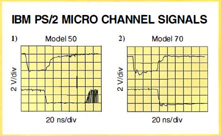
Figure A: IBM PS/2 Micro Channel Signals
Figure A: (1) is from a bus measurement in an IBM PS/2 Model 50, and (2) is
from a test of an IBM PS/2 Model 70. The two waveforms represent measurements
of the address strobe (upper trace) and command strobe (lower trace) lines and
are supposed to show two distinct phases of the transaction cycle. Notice that
on the Model 50 the lines actually overlap, causing a period of uncertainty
that add-in card manufacturers can handle by building in bus-settling delays
when designing Micro Channel cards. While the same waveforms on the Model 70
look more as they should, the quality of the signals on this bus is still
nowhere near as good as that of those measured on the NuBus of the Mac
IIfx.
Not all Micro Channel implementations are the same, even when they are from
IBM. Figure A shows two oscillographs; part 1 was taken from an IBM PS/2 Model
50, and part 2 from an IBM PS/2 Model 70. The two waveforms, ADL (Address
Latch) and CMD (Command), are supposed to delineate two different phases of the
transaction cycle.
Notice that on the Model 50 the waveforms actually overlap. While the same
waveforms on the Model 70 look more like the data book says they should, the
quality of the signals on this bus is still nowhere near as good as those on
the Mac IIfx's NuBus (see the text box "Signals on the Wire" on page 132).
Peripheral designers have to design cards that will work in all machines,
both slow and fast. The only way to ensure this compatibility is to avoid the
use of the advanced features that are available only on faster bus
implementations.
Therefore, an add-in card designer has to use logic slow enough to
accommodate the timing variations seen on the Model 50, instead of designing a
card that will be upgradable to the 160-MBps peak Micro Channel data rate.
For the RISC System/6000 series of workstations, IBM introduced another
version of the Micro Channel architecture, this one allowing for the use of
larger option cards. The workstation version of the Micro Channel began as a
32-bit-wide bus, but there are plans to upgrade it to a 64-bit-wide revision
supporting block transfers.
Thus, some manufacturers who embraced the Micro Channel early in its
development had to redesign their Micro Channel products at an early stage in
their life cycle. Not only did this reduce the number of available adapters, it
also increased their cost. But these early problems have been overcome, and
both Micro Channel and EISA have now achieved the levels of hardware
compatibility expected of them.
However, with the RISC System/6000 series of RISC workstations, IBM
introduced a Micro Channel with a larger physical card size (it is now almost
as big as an AT ISA card) and new, higher-speed, burst-transfer modes. So is
the Micro Channel add-in you are buying PS/2 Micro Channel-compatible or
RS/6000 Micro Channel-compatible?
Why Buy ISA Machines Now?
EISA and Micro Channel machines are still considerably more expensive than
their ISA counterparts. Part of this difference is due to how much the EISA
chip set costs the computer manufacturer. The other part is due to a
recognition that an EISA machine won't sell as well as an ISA system will. In
addition, only Intel currently ships an EISA interface chip. It is expensive
compared to the ISA chips, which are available from a number of vendors.
In return for the higher price of the EISA and Micro Channel systems,
greater levels of system performance are expected. But in actual use, this
expectation has often not been met. Meanwhile, many designers have found a
better way of increasing system speed: close coupling.
Close Coupling
RAM is the most speed-critical resource that a CPU needs. To improve system
speed and bypass bus limitations, you can closely couple the main memory system
to the CPU over its own dedicated bus.
Although the original XT had only 64K bytes of closely coupled (motherboard)
memory and needed add-in memory cards to run any significant software, most
computer systems sold today have several megabytes of high-speed, closely
coupled memory on the motherboard. Add-in memory cards are rarely needed. Thus,
bus-speed limitations no longer affect the CPU's ability to obtain data quickly
from its main memory.
Local Intelligence
The same design methodology is now being applied to all the subsystems that
make up a computer system. Vendors often claim that you need a fast bus for
faster video (for applications such as multimedia). But as Nick Baran warned
(see "The Bus Stops Here," February 1990 BYTE), none of these expansion buses
really has enough raw bandwidth to directly transfer pixels at the rates needed
for real-time video displays.
Peripherals need more local intelligence to off-load some of the host CPU's
computing tasks. This is already happening in two areas: drive controllers and
video display cards. The data rate of the ISA bus is slower than that of many
modern hard disk systems. However, if you mount a memory cache on the drive
controller, it acts as a buffer between the disk data rate and the bus data
rate.
Even though the disk speed of the original AT computers was limited to
around 260 KBps (the 2-to- 1 interleave data rate), most controllers now
operate at the 500-KBps rate of 1 -to- 1 interleave disks. The data from a
whole track is stored in memory on the drive controller. It is then available
when the host CPU is ready to use it. This architecture doubles system
performance without needing any changes in the bus itself.
Enter Localbus
Intel has defined a bus for closely coupling peripherals to the CPU. Called
Localbus, it essentially connects peripherals directly to CPU control lines.
Similar connections to VGA controller chips have yielded a significant
performance improvement over the same VGA chips on either EISA or Micro Channel
adapter cards.
True, there is a limit to the number of peripherals you can connect through
the Local bus. However, that limit is now mainly the limit of capacitive
loading. Placing the Local bus chips on the motherboard very close to the CPU
has reduced the inductive (transmission-line) component.
Moving beyond Localbus performance, CPU technology is migrating toward the
"PC on a chip." In that vein, the CPU is incorporating more and more of the key
peripherals into itself.
High-Speed RISC Connections
RISC processors are already operating at 50-MHz and 60-MHz clock rates,
requiring efficient connections between the CPU and memory and between the CPU
and peripherals. The SPARC Consortium has defined a bus, called MBus, that is
very similar to Localbus and incorporates several important innovations likely
to be seen in the very near future.
First, the MBus emphasizes the use of surface-mount technology to achieve
small size and, hence, low parasitic inductance and capacitance. Thus, the bus
never really becomes a "transmission line" (for electrically oriented readers,
it behaves more like distributed lumped capacitors). The maximum card size is
less than 20 percent of that of a standard AT expansion card, yet, by using
smaller (surface-mount) components, it has basically the same
functionality.
Second, the MBus uses a wider data transfer width: 64 bits. Since the bus
can operate at 40 MHz, the useful bandwidth is 80 MBps, and the peak rate is
320 MBps.
Third, you can stack multiple MBus modules. Unlike ISA, EISA, and Micro
Channel buses, the MBus modules are very close together, and very close to the
CPU. Thus, although transmission-line effects definitely exist, the ringing and
other artifacts occur at much higher frequencies and don't affect overall
system performance.
The Bottom Line
If you're planning to buy a Micro Channel machine today based on its promise
of extensibility to 160 MBps, forget it. The Micro Channel may support that
data rate one day, but just as you had to upgrade your CPU from 8086 to 286 to
386 to 486 to get their advantages, you will have to upgrade your system and
peripherals to get that sort of data rate.
The same situation pertains to ISA or EISA. Until all manufacturers design
their machines using the best technology available, the peripheral vendor will
have to compromise, thus limiting the performance your system can achieve.
Manufacturers are offering a lot of innovative solutions to overcome these
limitations. Unless you are running a Unix or NetOS-based network (which needs
blinding speeds from the drive controller), then ISA-based machines using
Localbus technologies will probably do the job.
Select a system that does what you want today. The industry will provide
brand-new products to choose from tomorrow.
Trevor Marshall is a consulting editor for BYTE. You can reach him on BIX
as "tmarshall"
|