|
@8088.adf ATI 8514/Ultra (mach8)
ATI 8514 Ultra Disk 1 of 2
ATI 8514 Ultra Disk 2 of 2
ATI 8514 Ultra Graphics Win 3.1 Supplement
(zipped RAW images; all files thx to Alexander Paterakis)
8514/Ultra User's Guide version 1.0, Oct 1990, B/W (compact version) (thx David Beem)
8514/Ultra User's Guide version 2.1, Apr 1992, color (thx Alexander Paterakis)
mach8 Drivers and Utilities (8514 Ultra)
Identifying ATI Products by Direct (Visual) Inspection
Using the BIOS Part Number to determine which ATI chip is on Your Product
Photos of the original box:
Front |
Back
(VGA Legacy)
8514 Ultra Old
8514 Ultra New
Adapter Module
Early 8514 Ultra
Adapter ROM
Adapter Resources
Video Controllers
ATI Ultra Specs
Supported Video Modes
Converting Card to MCA
Error Messages
Testing the 8514 Ultra
Troubleshooting
ADF Sections
8514 Ultra Old dated 9114, PCB P/N 109P011320
![Front [P]](/other/img/photo.gif) (thx Alexandros Paterakis)
(thx Alexandros Paterakis)
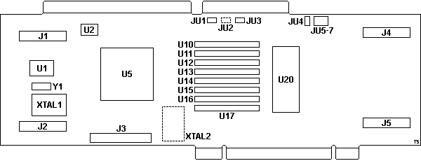
8514 Ultra New dated 9151, FCC ID EXMULTRA1, PCB P/N 1090011320
![Front [P]](/other/img/photo.gif)
![Back [P]](/other/img/photo.gif) (VGA Legacy)
(VGA Legacy)
Only minor layout differences. Unused gold fingers removed.
Drops JU2,
adds JU8.
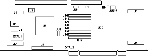
J1,2 Adapter Module headers - ISA
J3 VGA Pass Through Connector
J4,5 Adapter Module headers - MCA
JU1 EEPROM Enable/Disable
JU2 jumper pads, shunted (?)
JU3 Memory size select
JU4 I/O width select
JU5-7 IRQ select
JU8 Pixel Clock select
|
U1 ICS1394 / ICS1494M Dot Clock Gen.
U2 KM93C46 1Kbit serial EEPROM
U5 ATI 38800-1 Video Controller
U10-11 256x4 ZIP VRAM
U20 27C256-15 video BIOS ROM
XTAL1 33.0000 MHz osc
XTAL2 pads for osc (?)
Y1 14.318 MHz osc
|
J3 VGA Pass Through Connector. Not used
for MCA systems. Remember, this card uses the AVE
connector, being fed base video from on-board video or from the card in the BVE
slot.
JU1 EEPROM toggle: 1-2 Disable, 2-3 Enable (default)
JU3 Memory size select: On 512K, Off 1MB
JU4 I/O width select: 1-2 16-bit (default), 2-3 8-bit
JU5-7 IRQ select: JU5 IRQ2, JU6 IRQ3, JU7 IRQ5. Default: all disabled
Note: IRQs are not used by any software.
JU8 Pixel Clock select: 1-2 Clock, 2-3 Clock Bar (default)
U1 ICS1394 85 MHz Video Dot Clock Generator
(alt. datasheet)
ICS1494M 135 MHz Enhanced Video Dot Clock Generator (M suffix = SO package)
U10-17 256x4 ZIP VRAM,
TI TMS44C251-8,
NEC µPD42274V-8 or compatible.
Every other module is socketed on some cards (and possibly optional?).
Adapter Module PCB P/N 1090011100
![Front [P]](/other/img/photo.gif)
![Back [P]](/other/img/photo.gif) or 1090011110
or 1090011110
![Front (alt) [P]](/other/img/photo.gif)
Early 8514 Ultra
The back of the original box shows an early 8514 Ultra. A pre-production
sample?
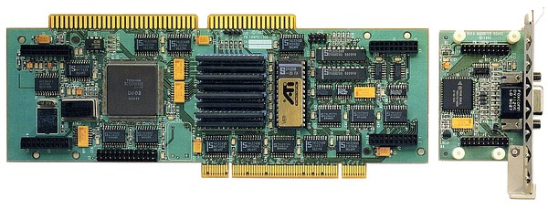
The PCB has a slightly different layout, there are 2 through-hole DIPs in
place of the 4 PLCC PALs, the jumpers are organized differently, and the main
chip (Toshiba gate array?) lacks the ATi branding, among other differences.
The Adapter Module is also slightly different - notice the resistor
network (not present on the later revisions) and the missing "notch".
Adapter ROM
1x 27C256-15 32Kx8 CMOS EPROM (U20)
1130111315 - ver. 1.15V1, 1990/12/25 (thx Alexander Paterakis)
11301113131 - ver. 1.31V1, 1991/5/12 (thx David Beem)
11301113140 - ver. 1.4V1, 1991/11/11 (thx David Beem)
SWAG: 113-01113nnn, where "113" is a prefix, "01113" means MACH8, and "nnn"
is either a two or three digit suffix showing BIOS version. "15" is version
1.15, etc. YMMW -LFO
Adapter Resources
Video Memory Address: A000-BFFFh
Video BIOS Address: C000-C7FFh
Video Port Address: 2E0-2E8h (Fixed)
Warning! COM4 uses I/O address 2E0h...
Video Controllers
ATI made a mixture of ISA and MCA products. The two video controllers of
interest here are the 28800 (SVGA) and the 38800 (8514). The ISA bus cards had
to use the 28800 in order to generate SVGA video, or use the video
pass-through. Some ISA cards were made with a 28800 / 38800 combo. Obviously, a
MCA accelerator card only needed the 38800 (8514) as it pulled the VGA (Base
Video) over the AVEC.
ATI Ultra Specs
(by Henry A Wor, original post HERE, edited)
The 8514 ULTRA provides a superset of the 8514/A, using the ATI 38800-1
(MACH8) with up to 1M of VRAM.
To use the MACH8's acceleration features you must switch to the MACH8/8514A
mode and program thru the MACH8's 8514A's style registers or the TSR AI
interface. The MACH8 features are just not available to VGA mode, BIOS, or VESA
driver.
There are a few books that have some info on programming 8514A's, but they
don't cover the MACH8's extensions (including additional non-8514A resolutions
like 600x800). On some of the major DOS oriented FTP servers (wuarchie,
simtel...) there can be found a collection of register definitions
(VGADOC.ZIP?) for various VGA chips including the ATI VGAWonder (and it
includes some 8514A chips as well, but not the ATI MACH8).
A few books that include some 8514A info:
- "Power Programming the IBM XGA" by Jake Richer
MIS Press ISBN 1-55828-127-4, 1-55828-127-9 (w/ disk)
- "Power Programming the IBM 8514A" by Jake Richer
ISBN unknown
- "Graphics Programming Solutions" by Julio Sanchez & Maria P. Canters(sp?)
McGraw Hill ISBN 0-07-911465-2(SC)
Example 8514A AI program hangs, but is easily fixed (doesn't switch back to
VGA mode when done). Also IBM has a technical reference book or two on the
8514A.
Supported Video Modes
640x480 Mode
60 Hz Non-interlaced
72 Hz Non-interlaced
800x600 Mode
56 Hz Non-interlaced
60 Hz Non-interlaced
70 Hz Non-interlaced
72 Hz Non-interlaced
76 Hz Non-interlaced
89 Hz Interlaced
95 Hz Interlaced
1024x768 Mode
60 Hz Non-interlaced
66 Hz Non-interlaced
70 Hz Non-interlaced
72 Hz Non-interlaced
76 Hz Non-interlaced
87 Hz Interlaced
1280x1024 Mode
87 Hz Interlaced
Converting Card to MCA
Remove the 4 screws on the back side of the adapter Module (the white screws
on the back of the board) and remove the nuts holding the existing bracket.
Install the parts as shown in the following illustration, fastening the plastic
clip first. Slide the three prong end of the Micro Channel bracket into the
plastic clip and then tighten the nuts.
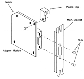
Mount the module with the MCA retaining bracket on the 8514-Ultra as shown
below. Fasten the retaining bracket on the 8514-Ultra using the four plastic
screws. Make sure the notch on the module is facing up (away from the MCA bus
connector).
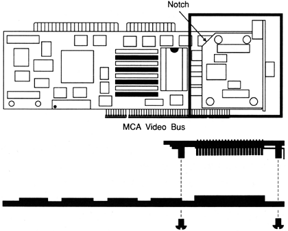
The 8514-Ultra must be installed in an AVE slot (Slot 3 in a 90, Slot 7 in
an 85 or 95). This bus slot contains additional connectors for the Video Bus
which is used by the 8514-Ultra to pass VGA signals through the monitor
connected to the 8514-Ultra.
Error Messages
14201 Video Adapter Not Detected - If card is present, this would
indicate a severe failure (i.e. I/O conflict with another board, bad bus
timing, bad gate array, or a bad board)
14202 Pass Through Connector Configuration Error - Not applicable
to MCA setup.
14203 Subsystem Failure - Severe failure.
14204 Graphics Subsystem Failure - Generic coprocessor error.
Treat as a severe failure. Ensure that no device uses COM4 (I/O address
2E8h).
14205 RAMDAC Failure - RAMDAC failure. Contact ATI Tech
support...
14206 Ram Failure - RAM data error. If one, two, or three RAM
chips are flashing, then the RAM chips are suspect. If every second RAM
chip is failing, check the JU3 (MEM_SIZE) jumper. If multiple RAM chips
are failing, the board is suspect.
14207 RAM Addressing Failure - Treat as a RAM Data Failure.
14208 POST ROM Checksum Failure - POST error. In MCA systems, the
ROM address is fixed at C680h. Which means the other devices must have
their ROM address moved.
14209 Configuration Error - Bad EEPROM. Run INSTALL utility again
and reboot. If problem persists, it is a board failure.
14213 FIFO Overflow Failure - Severe failure.
14214 Data Not Ready Failure - Severe Failure.
14215 ROM Paging Failure - Occurs if ROM shadowing is enabled for
the ROM or if there is an I/O conflict with register 46E8h of the VGA.
Testing the 8514 Ultra
The Diagnostic test has the following components:
- ROM Integrity Test - Performs CRC checksum on the boot ROM. Fails if
ROM is bad or there is an address conflict. This test is skipped if the
8514-Ultra has not been installed.
- Register Integrity Test - Performs reads and writes to some
8514-Ultra registers. An error with this test indicates a severe failure.
- FIFO Integrity Test - Tests FIFO. An error with this test indicates
a severe failure.
- RAMDAC Integrity Test - Tests RAMDAC.
- Video Memory Test - Tests integrity of VRAM.
If one, two, or three RAM chips are flashing, then RAM chips are
suspect.
If every second RAM chip is failing, check JU3 (MEM_SIZE)
jumper.
If multiple RAM chips are failing, the board is suspect.
- Test Sequences - There are five test sequences. 1MB boards will
perform sequences 1, 2, and 3. Minimum Mode Boards (512K) will perform test
sequences 1M, 2M, and 3. Any error within any of these tests indicates a Mach8
coprocessor failure or a bus timing problem.
Troubleshooting
System Won't Boot - Power down, disable EEPROM (shunt JU1), power up,
run INSTALL.EXE; power down; enable EEPROM (open JU1); power up; you should see
the 8514-Ultra.
Test Patterns OK, But Applications Won't Sync - Wrong monitor type
selected. Run INSTALL.EXE, change Monitor settings.
VGA Text Not Well Defined/Wrong Color - Change JU8 from Clock Bar to
Clock.
Network Cards - Many NICs have a default I/O address of 2E0h.
Reconfigure the NIC.
@8088h "ATI 8514/ULTRA"
Configuration not alterable
The configuration of this adapter can not
be altered.
If a CONFLICT occurs with this adapter, alter the
MEMORY LOCATION of other adapters until the conflict is
resolved.
<"Installed">
0C6800h - 0C7FFFh
|