|
MCGADIS.ZIP Disables MCGA (Epson Equity Ie, PS/2 Models 25/30 - untested)
Model 30 Video Interface Schematic (page 7 physical)
Model 25 Technical Reference (Video Subsystem - page 49 physical)
PS/2 Video Programming (MCGA parts only, HTML)
IBM PS/2 Model 25 and 30 MCGA Secrets Exposed!! (video by Hakemon Mike)
Smooth Scrolling on MCGA (proto-VGA) (video by PCRetroTech)
Epson Equity 1e (blog post by Ancient Electronics)
Overview
MCGA and VGA Video Modes
Systems with MCGA
IBM MCGA Components
Erroneous/False Display Characters
Epson Equity MCGA
MCGA Registers
Disabling MCGA
MCGA and VGA Design Teams
MCGA Ramblings
Overview
The MCGA "Multi-Color Graphics Array" subsystem is present on the planar
board of the original Models 30 and 25. It was never made available in form of
an adapter card. The only known "clone" that implemented MCGA was Epson Equity
Ie.
Feature-wise it's a superset of the older CGA "Graphics Adapter" standard,
but it uses analog video output (VGA compatible) and adds four new expanded
modes (640 x 350 line mode not supported):
- 320 x 200 graphics (APA) with 256 colors *
- 640 x 480 graphics (APA) with 2 colors *
- 40 x 25 text (8 x 16 char. box) with 16 colors *
- 80 x 25 text (8 x 16 char. box) with 16 colors *
* out of 262,144 colors total
The integrated MCGA will automatically use up to 64 shades of gray in
converting color modes of operations for display on the IBM 8525-001/-G01
(monochrome model). This allows users who prefer a monochrome display to
execute color graphics applications.
Note: MCGA does NOT provide compatibility with EGA
"Enhanced Graphics Adapter".
MCGA and VGA Video Modes
BIOS video modes introduced by the MCGA and VGA:
| Mode | Description | MCGA | VGA |
|---|
| 0 | 40 x 25 text, 16 colors (320 x 400 resolution) | Yes | No |
| 0 | 40 x 25 text, 16 colors (360 x 400 resolution) | No | Yes |
| 2 | 80 x 25 text, 16 colors (640 x 400 resolution) | Yes | No |
| 2 | 80 x 25 text, 16 colors (720 x 400 resolution) | No | Yes |
| 11h | 640 x 480 graphics (APA), 2 colors | Yes | Yes |
| 12h | 640 x 480 graphics (APA), 16 colors | No | Yes |
| 13h | 320 x 200 graphics (APA), 256 colors | Yes | Yes |
More info about video modes HERE (physical page 52).
The video subsystem supports a 31.5 kHz analog color display or 31.5 kHz
analog monochrome display. The system senses the type of display and matches
the initialization to it. If the system senses the presence of a monochrome
display, it sums the colors and outputs the video signal to pin 4 (green) of
the video connector on the system board (-Model 25).
Systems with MCGA
The MCGA subsystem was never implemented on an expansion adapter and (to our
knowledge) only exists as an on-planar feature in the following machines:
IBM MCGA Components
The IBM MCGA subsystem consists of:
- Video Memory Controller gate array (72X8300 or 11F8028, see ECA-023)
- Video Formatter gate array (72X8205)
- 256 x 18-bit color palette with three 6-bit DACs (Inmos IMSG171 RAMDAC)
- 64 KB of multi-port video DRAM (i.e. 2x NEC µPD41264C-15 64Kx4 DRAM)
- 8 KB of SRAM for character generator (i.e. Epson SRM2264(L)M-12 8Kx8 SRAM)
- Support ("glue") logic
MCGA Block Diagram
Video Memory Controller
P/N: 72X8300 (old) or 11F8028 (new) - see ECA-023
Gate Array: Seiko-Epson SLA6430J
72X8300 Die Photo (21808x21778px! 154 MB)
"zoomable" version (both courtesy of John McMaster)
Model 25 "Type 1" planar: 72X8300
Model 25 "Type 2" planar: 11F8028
Model 30 "P-Planar": 72X8300
Model 30 "Greenock Planar": 11F8028
Video Formatter
P/N: 72X8205
Gate Array: Seiko-Epson SLA6330J or IBM GA (early samples only?)
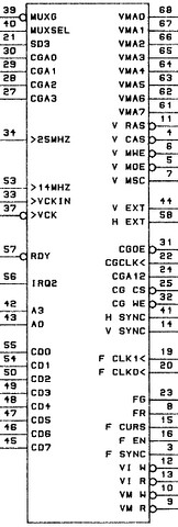
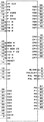
Gate Array Pinouts
 |
 |
72X8300
Video Memory Controller |
72X8205
Video Formatter |
Erroneous/False Display Characters (ECA 023, M/T 8525)
Ed. This ECA was only issued for Model 25, but
some Model 30 planars also come with the affected gate array (72X8300).
Physical Check
Affected 8525 systems will have part number 72X8300 printed on the video
control gate array chip. This chip is in position U11 on the 8525 system board.
U11 is a 1-inch square chip located near the system board memory. Only system
boards with P/N 72X8300 printed on the chip are eligible for replacement under
this ECA.
Detail
If problems are experienced with an 8525 using an application that loads
more than one character font into memory, the system board may require
replacement. An additional character font may also be referred to as an
"extended character set." These problems may be reported as erroneous or
unidentifiable characters, or characters that are unexpectedly underlined, and
may occur intermittently. If these symptoms are reported, and if the chip in
position U11 meets the physical check requirements, replace the 8525 system
board with FRU P/N 96F7390. Changes have been made to the current level 8525
system boards to eliminate these problems.
Notes
Order parts through normal distribution. All replaced system boards should
be returned via UPR. RECORD ALL TIME AND MATERIALS TO SERVICE CODE 33, ECA023,
AND OTHER OFFICE 990.
Epson Equity MCGA
![[P]](/other/img/photo.gif "Front") (source)
(source)
The Equity Ie / PSE 30 MCGA subsystem uses a higher level of integration
with the Video Memory Controller and Video Formatter implemented in the same
gate array. The other components are equivalent to the IBM
implementation:
- Epson E01151EC MCGA gate array
- 256 x 18-bit color palette with three 6-bit DACs (Inmos IMSG171 RAMDAC)
- 64 KB of multi-port video DRAM (TI TMS4461-12NL 64Kx4 DRAM)
- 8 KB of SRAM for character generator (Sony CXK5864BP-12L 8Kx8 SRAM)
- Support ("glue") logic
MCGA Registers
Used I/O addresses:
- 3D4h & 3D5h - Video Memory Controller gate array
- 3D8h — 3DFh - Video Formatter gate array responds to I/O addresses
- 3C6h — 3C9h - RAMDAC Color Palette (programmed through the Video Formatter)
See the Technical Reference
(page 57 physical) for more information.
The MCGA subsystem can be enabled/disabled by toggling bit 2 of the System
Board Control Register at address 65h (0: disabled, 1: enabled).
Disabling MCGA (slightly edited, source HERE)
Ed. Tom: This is for Epson Equity Ie, but the
same method should work for all 8086-based PS/2 Models 25 and 30. This is
possible because all 3 machines map the Video Enable/Chip-Select line to bit 2
of the System Board Control Register at address 65h.
When using Lotus 1-2-3 (ver. 2.01) with the Hercules Monochrome board or an
Epson MGA board set for monochrome mode, the system displays garbage (usually a
checker board pattern) when using graphics. This also occurs if the 90 x 25
text mode is selected in the Lotus INSTALL program, since Hercules graphics
mode is utilized.
The solution for this problem is to disable the internal MCGA video by
creating and using the program listed below. Run the MS-DOS supplied DEBUG
program and type in the following (Ed. or just
download the binary HERE):
                     ; - Comments only - do not type in -
-A                   ; Enter assembly mode
xxxx:0100 in AL,65   ; Get current value of equipment enable register.
xxxx:0102 and AL,FB  ; Clear video enable bit to disable MCGA.
xxxx:0104 out 65,AL  ; Output new value to the equipment enable register.
xxxx:0106 int 20     ; End of program.
xxxx:0108            ; Press <Enter> key (again) to leave assembly mode.
-NMCGADIS.COM        ; Specify name of program as "MCGADIS.COM".
-RCX                 ; Edit CX register.
CX 0000              ; Currently contains 0000.
:8                   ; Specify 8 bytes to be saved.
-W                   ; Save program to disk.
Writing 00008 bytes
-Q                   ; Quit DEBUG.
Note: The xxxx segment value will vary
depending on system memory usage and is irrelevant here.
The MCGADIS.COM program can now be found in the
current directory. It can be added to the AUTOEXEC.BAT file or run directly,
before running Lotus. This program will enable a Hercules Monochrome board or
Epson MGA board to be used in monochrome mode, but will not allow a CGA card to
be used.
MCGA and VGA Design Teams
niksgarage said:
I was working in Boca in 1985-1987 .. happy times. ... MCGA
and VGA were two design teams working in different buildings, separated by a
parking lot but shared a cafeteria. One interesting feature was MCGA used a
VRAM design, which was a little more sophisticated than VGA's plain ol' DRAM
design.
MCGA Ramblings
(from "tw11tube" aka "mkarcher")
"tw11tube" said in a reply to Hakemon Mike's
IBM PS/2 Model 25 and 30 MCGA Secrets Exposed!! video.
It's not true that the MCGA card "has no BIOS" in the sense that the MCGA
hardware would work with with an standard IBM PC/XT BIOS with CGA/MDA support.
The system BIOS of the PS/2 Model 30 (Ed. and 25)
includes specific MCGA support functions. Programming video timings on the MCGA
is absolutely not CGA compatible, but the registers affecting timing are write
protected by a bit unknown to CGA software, whereas other CRTC registers are
similar enough to CGA registers to provide some amount of software
compatibility.
As you can see from the mode numbers on MCGA, IBM obviously assigned them
after handing out mode numbers to EGA and VGA. Having mode 11h (640x480
two-color) and mode 13h (320x200 256 colors) supported, but not having mode 12h
in between would be very surprising if the numbers haven't been chosen from an
already established set of mode numbers. So while MCGA is technically something
like a Super-CGA, it seems to be integrated into the PC universum after VGA.
It's not impossible that IBM already had the MCGA in mind when they designed
the framebuffer-only mode 13h and 11h for their VGA, though.
Non-enhanced Monkey Island does use the 256 color mode, but runs it as
16-out-of-256K colors all the time, so it's not "in 256 colors" even if it is
"in the 256 color mode". You need the VGA remake to get 256-color graphics.
The connections from the video memory gate array to the RAMDAC go to the
processor interface of the RAMDAC (provides register access), but not to the
video side of the RAMDAC. It's more like the video memory gate array and the
RAMDAC are on the same 8-bit I/O data bus than "the video memory gate array
knows what the RAMDAC is doing".
The main point of the formatter is to take the bytes from the video RAM (and
the font RAM in text mode), and make a stream of pixels out of it. It most
likely does not do the double-scanning, because double scanning means the same
RAM data needs to be scanned out twice - and the only chip having control over
the address lines of the video RAM is the video memory gate array. The
formatter gate array needs to understand text mode, 4-color modes (4/5),
2-color modes (6/11h) and 256-color modes (13h).
The part around the RAM are the two 8-bit latches and an inverter. The two
8-bit latches are used as a kind of shift register: Video data from the VRAM
serial output pins is latched by the first '374, and then transferred to the
second '374. This makes the first 374 contain the attribute byte in text mode,
whereas the second 374 still has the character code byte. The output of the
second 374 is directly wired to the font RAM, and the only way to address it.
This is the reason for the strange font transfer scheme of the MCGA. The
inverter is used to help controlling the output enable of the attribute latch
and the font RAM, as well as generating chip select signals for the font
RAM.
15:07 - this is wrong.
MCGA also switches the dot clock in software. The tech ref has it on page 1-50:
Mode control (3d4h, index 10h), bit 4 is documented as "clock select". IBM only
documents 1 = 25.175 MHz, and "forgot" to document 0 = 14.318 MHz. You are
right about the monitor type jumper, but the jumpers are just read by the BIOS
that then programs the MCGA accordingly.
If you want to know about the real-time clock (which is missing from the
model 25 manual): Take a look at my post
HERE. 15.7
kHz is not off a bit. We are just lazy when we say 15 kHz. System M (usually
called NTSC) TV video timing is supposed to have 15.734 kHz, and CGA
approximates it with 114 characters of 8 pixels at a pixel clock of 14.318 MHz,
which yields 15.6996 kHz. Your PS/2 is just fine. MCGA and VGA provide
reasonable BIOS compatibility on font setting, as long as you observed some
restrictions, like MCGA fonts getting active only after using the "select font
banks" call, whereas they go effective immediately on EGA/VGA.
|