Source: BYTE IBM Special Edition Fall 1988, physical page 191+
Author: Richard Wilton
The VGA is the video sub-system built into IBM's PS/2 Models 50, 60, and 80.
It is also widely available as an adapter for the IBM PC XT and AT. In terms of
capability and performance, the VGA is essentially a mildly improved version of
the EGA. Surprisingly, however, the VGA is much more flexible than the EGA in
terms of the resolution of the video modes that it can display, particularly
when you use it with a variable-frequency video monitor.
Like the EGA, the VGA has several programmable control components, including
a CRT controller (CRTC), a sequencer, an attribute controller, and a graphics
controller. You can program each to modify essential timing signals and
addressing modes within the video subsystem. The VGA's ROM BIOS contains a set
of routines, invoked through interrupt 10 hexadecimal function 0, that program
the VGA controllers into any of 24 different configurations (video modes).
Each of the VGA's controllers has a number of registers whose contents
control their function. The VGA ROM BIOS contains tables of appropriate
register values for each supported video mode, so most programmers call the ROM
BIOS to select video modes instead of updating the registers directly. If,
however, you want to create video modes unsupported by the video BIOS, you need
to know what values to store in these registers to obtain the video
configuration you want.
Why take the trouble to create your own video modes? The usual reason is to
obtain higher-resolution graphics or more displayed text than the usual ROM
BIOS video modes can provide. Some widely used commercial applications,
including Microsoft Word and Lotus 1-2-3, can do this for you. If you want
higher resolution in your own applications, however, you need to do some extra
programming yourself.
Video Mode Control
You can differentiate video modes from each other in several ways:
- Vertical resolution: number of rows of pixels (scan lines) displayed on the
screen.
- Horizontal resolution: number of characters or pixels per row.
- Data representation in the video buffer.
- Attribute decoding: colors, blinking, and so on.
When you program the VGA, you have a great deal of control over vertical and
horizontal resolution. You have much less flexibility in regard to data
representation and attribute decoding because of the VGA's hardware design. For
this reason, the easiest way to set up alternative VGA video modes is to use
the ROM BIOS mode-set routines to establish a baseline video mode, and then
modify the horizontal and vertical resolution to produce a new video mode.
Video Display Timing
Controlling the resolution of the displayed image is -like many other
activities in life- a matter of timing. Both horizontal and vertical resolution
are related to the timing of the VGA's output signals that control the electron
beam in the video monitor. The image on the video screen is not static, of
course. It is produced by the cyclic sweep of the monitor's electron beam
across and down the screen (see figure 1). The screen image is completely
refreshed between 50 and 70 times per second, depending on the video mode.
 Figure 1: On a video screen, the electron beam's scan cycle
starts with the first pixel of the displayed video buffer data near the upper
left corner of the screen. Scan lines are traced horizontally, left to right,
then retraced down and across, right to left. In one scan line of a 640- by
480-pixel I6-color graphics mode, the horizontal total (100) specifies the
duration of one complete horizontal scan cycle. Horizontal displayed (80)
specifies the amount of displayed data. Horizontal sync starts at character
clock 84 and lasts for 12 character clocks, so there are 4 characters of
overscan at each end of the scan line. The vertical displayed (480) specifies
the number of scan lines of displayed data. Vertical sync starts at scan line
503 and lasts for 2 scan lines, so there is a total of 42 scan lines of
vertical overscan above and below the screen image.
Figure 1: On a video screen, the electron beam's scan cycle
starts with the first pixel of the displayed video buffer data near the upper
left corner of the screen. Scan lines are traced horizontally, left to right,
then retraced down and across, right to left. In one scan line of a 640- by
480-pixel I6-color graphics mode, the horizontal total (100) specifies the
duration of one complete horizontal scan cycle. Horizontal displayed (80)
specifies the amount of displayed data. Horizontal sync starts at character
clock 84 and lasts for 12 character clocks, so there are 4 characters of
overscan at each end of the scan line. The vertical displayed (480) specifies
the number of scan lines of displayed data. Vertical sync starts at scan line
503 and lasts for 2 scan lines, so there is a total of 42 scan lines of
vertical overscan above and below the screen image.
As each scan line of pixels is displayed, the electron beam's intensity is
modulated by signals generated by the VGA. (In a color monitor, there are three
adjacent electron beams, one for each primary color, but for the purposes of
video display timing, they can be regarded as a single beam.) The monitor moves
the beam from left to right at a constant rate across each scan line and
downward from scan line to scan line. The VGA generates a horizontal sync
signal that controls when the monitor deflects the beam from the rightmost end
of one scan line to the start of the next scan line (horizontal retrace). There
is also a vertical sync signal that controls the deflection of the beam from
the bottom of the screen back to the upper left corner (vertical retrace).
The VGA is always programmed so that the amount of time required to display
data from the video buffer is less than the total amount of time it takes to
sweep the electron beam horizontally and vertically. The extra time is spent in
horizontal and vertical overscan. You can assign a color to the overscan area
(also known as the border area) of the screen to provide a visual frame for the
displayed video data, but that area's basic purpose is to center the displayed
image on the screen.
You can control the horizontal timing signals generated by the VGA' s CRT
controller by updating the appropriate CRTC registers. The timing values that
you store in these registers are measured in "character clocks." A character
clock corresponds to 8 pixels in VGA graphics modes and either 8 or 9 pixels in
alphanumeric modes. You might want to think of a character clock as a unit of
time (i.e., the time required to display one character's worth of data on the
screen).
The key parameters that control horizontal timing are as follows:
- Horizontal total. The total amount of time spent in displaying each scan
line, including the time required for horizontal retrace.
- Horizontal displayed. The number of character clocks of data displayed from
the video buffer in each scan line. The difference between the horizontal total
and the horizontal displayed parameters describes the amount of horizontal
overscan.
- Horizontal sync. The character clock at which the horizontal sync pulse
begins.
The timing parameters that control the vertical size and on-screen location
of the displayed image are analogous to those that control horizontal timing.
Vertical timing parameters are usually specified in terms of number of scan
lines. As with character clocks, you might want to consider a scan line to be a
unit of time (i.e., the amount of time it takes to draw one scan line on the
screen and return the electron beam to the beginning of the next scan
line).
Here are the vertical timing parameters you need to consider when you
establish a VGA video mode:
- Vertical total. The total number of scan lines in one complete refresh
cycle.
- Vertical displayed. The number of scan lines of data displayed on the
screen. The difference between the vertical total and the vertical displayed
parameters determines the amount of vertical overscan.
- Vertical sync. The scan line in which the vertical sync pulse begins.
VGA Timing Constraints
In order to use these general timing parameters to program the VGA, you need
to know the basic timing frequencies used by the VGA and by your video monitor.
There are three different control-signal frequencies or rates to consider: The
rate at which pixels are displayed, the rate at which the electron beam sweeps
across the scan lines, and the rate at which the entire screen image is
refreshed. These three rates are commonly called the dot rate, the horizontal
scan rate, and the vertical scan rate.
Dot rate. The rate at which the video subsystem displays pixels is
called its dot rate; this frequency is also known as the pixel rate or the
video bandwidth. This rate is established by a high-frequency crystal
oscillator called the dot clock. You can program the VGA to use one of several
dot clocks with different frequencies. Two different crystal oscillators are
built into the VGA with frequencies of 25.175 MHz and 28.322 MHz; you can
select a third oscillator from the auxiliary video connector on the system
board of a PS/2 Model 50, 60, or 80. Horizontal scan rate. The horizontal scan rate is the number of scan
lines displayed per second. When you program the VGA, you indirectly specify a
horizontal scan rate by specifying the total number of pixels contained in each
scan line. If you divide the dot-clock frequency by the total number of pixels
per scan line, you get the horizontal scan rate. Vertical scan rate. The vertical scan rate (also called the refresh rate
or frame rate) is the number of times per second that the screen is refreshed.
You determine the vertical scan rate by programming the VGA to display a
specified number of scan lines during each refresh cycle. You can calculate the
vertical scan rate by dividing the horizontal scan rate by the number of scan
lines per frame.
The key to establishing alternative VGA video modes lies in programming the
VGA to produce timing signals that fall within the limitations of your monitor.
When you set up a video mode by programming the VGA, you must select a dot
rate, horizontal scan rate, and vertical scan rate that lie within the
tolerances of the monitor you're using. I've listed the tolerances of a few
VGA-compatible monitors in table 1.
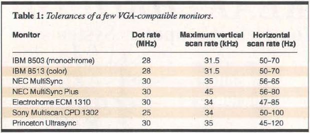
Table 1: Tolerances of a few VGA-compatible monitors
For example, consider the default ROM BIOS video mode 12h-that is, 640- by
480- pixel 16-color graphics mode. This mode is designed to work with IBM's
PS/2-compatible monitors, which expect a horizontal scan rate of 31.5 KHz. The
BIOS uses the VGA's 25.175-MHz dot clock in this video mode, so you can easily
determine the relevant timing constraints.
To compute the horizontal total, you divide the dot rate by the horizontal
scan rate to obtain the number of pixels per scan line. Then you divide this
value by 8 (the number of pixels per character clock) to determine the number
of character clocks per scan line:
Horizontal total = (25175000/31500)/8 = 100 character clocks
Since each scan line contains 640 pixels of data, the horizontal displayed
parameter is 640 divided by 8, or 80. The extra 20 character clocks represent
the time spent in horizontal overscan and in horizontal retrace. To center the
displayed pixel data, the horizontal sync signal starts at the eighty-fourth
character clock, and the horizontal sync pulse lasts for 12 character clocks.
The result is a scan line with 4 character clocks of overscan at each end.
The ROM BIOS relies on similar calculations to determine the vertical timing
parameters. The BIOS sets up this video mode so that 60 frames are displayed
per second. This vertical scan rate lies in the middle of the tolerance range
of IBM's PS/2 video monitors. The vertical total, measured in scan lines, is
the quotient of the actual horizontal scan rate (scan lines per second) and the
desired vertical scan rate of 60 frames per second:
Vertical total = (25175000/(100 x 8)) / 60 = 524 scan lines
The vertical displayed parameter is 480, the number of rows of pixel data
that are displayed in this video mode. The remaining 44 scan lines represent
vertical overscan plus the time required for vertical retrace. The BIOS starts
vertical retrace after 503 scan lines and specifies the duration of the
vertical sync pulse to be 2 scan lines. Thus, the 480 scan lines of video data
are displayed with a total of 42 (524-480-2) scan lines of vertical overscan
above and below.
Video-Mode Programming
Once you decide what the horizontal and vertical timing parameters will be
for a video mode, you can program the VGA to display it. There are five tasks
you must perform to coordinate the different components of the VGA
subsystem:
- Program the CRTC.
- Program the sequencer.
- Select a
dot-clock frequency.
- Specify the displayed character height.
- Update relevant ROM BIOS variables.
You program the VGA's controllers through a set of I/O ports (see table 2).
You must access these ports with either assembly language IN and OUT
instructions or their high-level-language equivalents. To access the ROM BIOS,
you need to execute interrupt 10h, either directly in assembly language or
through a high-level-language construct such as the int86( ) function in
Microsoft C.
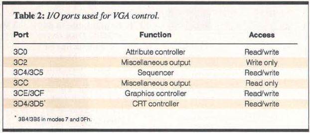
Table 2: I/O ports used for VGA control.
Most of the VGA's control over the horizontal and vertical timing parameters
is obtained through the CRTC. The CRTC controls the duration of the horizontal
and vertical timing signals sent to the monitor. It also synchronizes the
timing signals with the rate that data is extracted from the video buffer and
processed by the display circuitry. You control these functions by updating the
appropriate CRTC registers (see table 3).

Table 3: VGA CRT controller registers used for video-mode programming
To update a CRTC register, you must write a register number to I/O port 3D4h
and then write the register's new value to port 3D5h (see listing 1).
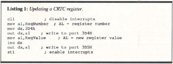
Listing 1: Updating a CRTC register
There are a couple of tricks to CRTC programming on the VGA. First, you can
use a single 16-bit port write to obtain the same results:
;AL = register number
mov al,RegNumber
;AH = new register value
mov ah,RegValue
mov dx,3D4h
;Write to port 3D4h/3D5h
out dx,ax
If you don't use 8-bit port accesses, be sure to clear the interrupts.
Otherwise, a hardware interrupt may occur between the port writes and disrupt
your program by transferring control to a service routine that does its own
CRTC programming.
Also, if you're programming in ROM BIOS modes 7 or 0Fh, use ports 3B4h and
3B5h instead of 3D4h and 3D5h. These port addresses mimic those that are used
in the Monochrome Display Adapter; they let you operate both a VGA and another
color video subsystem in the same computer.
Unlike the control registers in previous IBM video subsystems, you can
perform both reads and writes to the VGA' s control registers (see listing 2).
This is particularly convenient because it lets you save the current state of
the CRTC registers before you modify them.
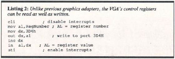
Listing 2: Unlike previous cards, VGA control registers can be read and written
The VGA sequencer has several interrelated functions, including
synchronization of the video subsystem's character clock with the dot clock.
The character clock determines the rate at which bytes of data from the video
buffer are displayed. You can set the character clock so that one character is
displayed every 8 or 9 ticks of the dot clock. In other words, each byte of
data in the video buffer may be displayed as either 8 or 9 horizontal pixels,
depending on how you program the sequencer.
In default VGA alphanumeric modes, the VGA displays 9 pixels for each
character on the screen. In EGA-compatible 350-line alphanumeric modes and in
graphics modes, the system programs the sequencer to display 8 pixels per
character. The extra (ninth) pixel increases the sharpness of displayed text,
but omitting the extra pixel allows you to display more characters across the
screen.
You would access sequencer registers through I/O ports 3C4h and 3C5h (see
table 4). The same programming techniques I've shown to access the CRTC will
work for accessing the sequencer registers, but there is a catch: When you
select a new dot clock or change the number of pixels per character, you must
temporarily reset the sequencer by toggling bit 1 of its reset register. An
example of this is in listing 3, which programs the sequencer to generate 8
pixels per character.
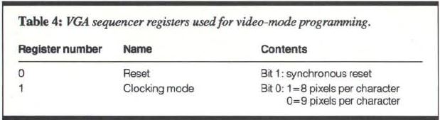
Table 4: VGA sequencer registers used/or video-mode programming

Listing 3: Programming VGA sequencer to produce 8 pixels per character
Bits 2 and 3 of the VGA's miscellaneous output register specify which dot
clock frequency to use (see table 5). You can update this register by reading
I/O port 3CCh to obtain its current value, masking bits 2 and 3, and then
writing port 3C2h. When you do this, however, you should temporarily reset the
sequencer, as in the previous program example.
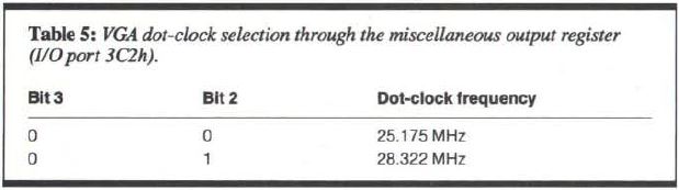
Table 5: VGA dot-clock selection via miscellaneous output register (I/0 port 3C2h).
In default alphanumeric modes, the video BIOS configures the VGA to display
25 rows of characters. For example, in 400-line alphanumeric modes (the
power-on default), each character is 16 scan lines high. You can modify any
alphanumeric mode to display more than 25 rows of characters simply by using
shorter characters that are displayed in fewer scan lines.
Bits 0 through 4 of CRTC register 09h, the maximum scan-line register,
control the displayed height of alphanumeric characters. The value in this bit
field is one less than the character height in scan lines. Thus, in default
alphanumeric modes, the value in bits 0 through 4 is 01111 binary (0Fh). If,
for example, you change this value to 00111 binary (07h), the CRTC would
display only 8 scan lines per character, so you would have a video mode that
consisted of 50 character rows instead of 25.
Although you can update the maximum scan-line register directly, it is
usually better to use the ROM BIOS to do the work for you. The ROM BIOS
provides considerable flexibility in setting the displayed height of
alphanumeric-mode characters because it lets you select an appropriate
character set at the same time. For example,
;AH = 11h (ROM BIOS function number)
;AL = 12h (sub function number)
mov ax, 1112h
mov bl,0
;Call the video BIOS
int 10h
This sequence calls the video BIOS to display a character set in which each
character is only eight scan lines high. The BIOS loads the character set into
the hardware character generator, programs the CRTC appropriately, and updates
its global data area with the new number of character rows displayed.
Two Examples
I've created two programs that automate the process of calculating the CRTC
register values for different video modes. (I used Microsoft C 5.0 to compile
these programs. If you use another vendor's C compiler, you may need to rewrite
the references to the int86() library call that invokes interrupt 10h.) The
alphanumeric-mode program, AVMODE, lets you specify the number of displayed
character columns, the size of the displayed character matrix, and an optional
horizontal adjustment factor that helps to center the screen image. For
example, you can create a 90-column mode that uses 8 by 8 characters by running
the program with this command:
AVMODE 90 8 8
If the resulting image is not centered horizontally, you can also specify an
adjustment to the horizontal sync position. For instance, you could shift the
image one character position rightward by executing the program with the
following:
AVMODE 90 8 8-1
The program uses the video BIOS character-generator interface to give the
CRTC the specified height of the character matrix. It then programs the
sequencer to display characters that are either 8 or 9 pixels wide. The rest of
the program sets up the CRTC with horizontal timing parameters appropriate for
the number of characters to be displayed.
For simplicity, AVMODE.C performs all its sequencer and CRTC programming in
high-level subroutines. In practice, however, you should probably use assembly
language to do this. The reason is that the C functions inp( ) and outp( )
compile as subroutine calls instead of in-line IN and OUT instructions. This
means that subroutines that call inp( ) and outp( ) (e.g., SetSeqReg( ) and
SetCRTCReg( )) are somewhat lengthy and too susceptible to interference from
hardware interrupts to be thoroughly reliable.
You will find that an IBM VGA (in a PS/2 Model 50, 60, or 80) or IBM VGA
adapter can produce an alphanumeric mode with about 96 8-pixel characters per
row using an IBM PS/2 monitor. Higher resolutions exceed the tolerances of
IBM's monitors.
If you use a variable-frequency monitor, you can push the VGA up to 132
characters per row. (Of course, the characters are pretty tiny when you squeeze
132 in a row.) You will probably have to adjust the vertical hold control on
your monitor, because the vertical scan rate with a 132-character alphanumeric
mode is only 51.5 Hz. Also, you may notice that the screen image flickers when
you display a large, bright field of color; this, too, is a consequence of the
low vertical scan rate.
Use the PC-DOS CLS command with caution if you use AVMODE to change the
number of displayed character rows. The video BIOS keeps track of the number of
character rows in a byte in its global data area at address 0040:0084h, but
PC-DOS ignores this value and assumes that there are always 25 rows of data to
clear. If you program the CRTC to display 50 lines of data, CLS clears only the
top half of the screen. To avoid this problem, you could write your own
screen-clear command (see listing 4), using interrupt 10h function 6.
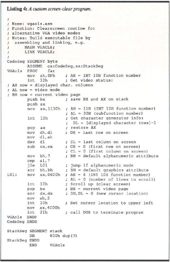
Listing 4: A custom screen-clear program
GVMODE, the graphics-mode example, requires you to specify the number of
pixels to be displayed horizontally and vertically. For example, to set up a
720-by 480-pixel 16-color graphics mode, you execute GVMODE as follows:
GVMODE 720 480
The program uses the desired resolution to select which of the VGA' s
dotclocks to activate. This lets GVMODE produce a wider range of video modes
than it could if it relied on just one dotclock frequency. Apart from these
small differences, however, GVMODE's operation is similar to that of
AVMODE.
With an off-the-shelf IBM VGA and PS/2-compatible monitor, you can use
GVMODE to produce a graphics mode with about 720- by 512-pixel resolution,
although displaying this many pixels pushes IBM's analog monitors to their
limits. However, 800- by 600-pixel resolution is well within the tolerances of
a non-IBM variable-frequency monitor.
Again, higher resolutions imply lower vertical scan rates. You may find that
the resolution you want to use in your programs is limited by the amount of
perceptible flicker on the screen at lower vertical scan rates. [Editor's note:
The source code for AVMODE.C and GVMODE.C is available in a variety of
formats.]
VGA Clones
The ICs that IBM used in the VGA subsystem are proprietary. IBM's
competitors have been forced to reverse-engineer the VGA hardware to produce
the same capabilities in their own products. This means that a VGA clone may
not necessarily be hardware-compatible with an IBM VGA. Two ways the clones may
differ are in the values stored in the control registers and in the dot-clock
frequencies you can use.
The register-programming techniques I've described are not applicable to all
VGA subsystems because not all VGA clone makers have designed their CRT
controllers to use the same register values as IBM's. For example, when you try
to program the CRTC on Video Seven's VEGA VGA, you'll discover that many of the
CRTC registers require different values than they do with a true-blue IBM VGA.
Other adapters, including the Paradise VGA Plus, expect the same register
values as an IBM VGA, so programming these clones is much easier.
Manufacturers of VGA clones generally implement higher-resolution, non-IBM
video modes using a higher-frequency dot clock. For example, the Paradise VGA
Plus uses a 36.000-MHz dot clock in 132-column alphanumeric modes and in 800-
by 600-pixel graphics modes. With the higher dot-clock rate, the resulting
horizontal and vertical scan rates in these modes are higher than they are when
you use a true-blue VGA's 28.322-MHz dot clock. The scan rates are much closer
to the middle of the tolerance range of most monitors, and the increased
vertical scan rate results in less flicker.
Alternative Video Modes
Clearly, these alternative VGA video modes are not for everybody. Using them
requires some understanding of how the video subsystem works. However, if
you're writing a program that does fullscreen text or graphics output, you
should be able to incorporate support for alternative video modes without too
much anguish.
On the other hand, alternative video modes are rarely supported by
off-the-shelf software. Making your favorite spreadsheet or word processor run
in an alternative video mode might require you to customize the program's
installation process. If you use a VGA clone with a BIOS that supports non-IBM
video modes, you might be able to include special drivers provided by the
clone's manufacturer when you install your software. Otherwise, you may need to
patch an existing driver or write your own driver in order to exploit an
alternative video mode.
Nevertheless, there is a reasonable amount of support in the VGA hardware
and video BIOS for alternative video modes. If you program the hardware
carefully and exploit the services offered in the ROM BIOS, you can run
applications with higher resolution or more characters than the usual ROM BIOS
video modes provide.
Richard Wilton is the author of Programmer's Guide to PC and PS/2 Video
Systems and coauthor of The New Peter Norton Programmer's Guide to the PC and
PS/2, both published by Microsoft Press. He lives in Los Angeles, California,
and he can be reached on BIX c/o "editors."
|