|
Power Supply Pinout
Test PSU
8550 / 50Z PSU Specs
8570 PSU Specs
7561 / 62 PSU Specs
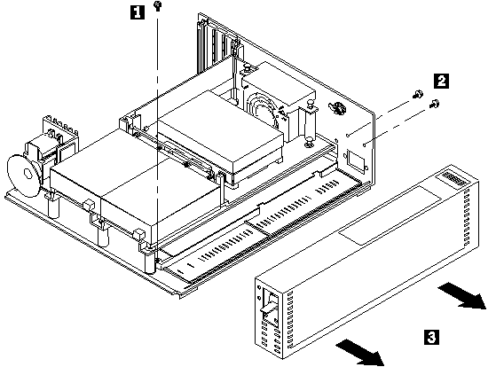
Remove PSU
Power Supply Cleaning
Clean 8550 / 50z PSU
Remove and clean 8570 PSU
8550 Power Connector Hack (David Beem)
8570 Power Connector Hack (Peter Wendt and Major Tom)
Power Supply Pinout
Same for 8550 (94 W), 8570 (132 W) and 756x (180 W).

Top row, odd numbered pins, left to right: 1-49
Bottom row, even numbered pins, left to right: 2-50
| Pin | Description |
|---|
| Even pins 2-48 | DC Return (Ground) |
| Pin 1 | -12 V DC |
| Odd pins 3-13 | +12 V DC |
| Odd pins 15-47 | +5 V DC |
| Pin 49 | System Status |
| Pin 50 | Power Good |
Test PSU
Power-off the system. Remove power supply and place it with connector facing
up. Power-on the power supply and check for voltages listed below. If voltages
are not correct, check the power cord for continuity. If power cord is good,
replace the power supply.
Note: Sometimes AC power cords develop a set in
the plug contacts so that there is intermittent or poor contact with the AC
receptacle pins in the PSU. Try reseating or swapping out the AC cord.
| Vdc Min |
Vdc Max |
Gnd (-) Pin |
Pos (+) Pin |
| -9.0 |
-15.0 |
2 |
1 |
| +9.0 |
+15.0 |
2 |
3 |
| +3.7 |
+6.2 |
2 |
15 |
Note: If you have a
dead PSU with no voltages, suspect F1 or F2 have blown.
8550/Z PSU Specs
ASTEC Model No.: AA13621, IBM P/N 90X9527, IBM FRU P/N 90X9366
| Voltage (DC) | Pin # | Current / Pin |
|---|
| -12 V | 1 | 410 mA |
| +12 V | 3,5,7,9,11,13 | 350 mA |
| +5 V | 15-47 odd # only | 760 mA |
| DC Return | 2-48 even # only | 640 mA |
| System Status | 49 | — |
| Power Good | 50 | — |
Max continuous output power is 94 W.
No side blower. The blower plugs into the motherboard, is
supported by two plastic snaps to top rack, and it blows out the rear of
the 50/50z unit. Bottom of power supply does not have a screen, it has finely
punched holes, 11 or 10 holes across, the length of power supply.
Cases vary color, gold/silver. Security Torx - 5 on side, 2 on top.
Like the Model 70 supplies, except no side blower, and lower rating.
8570 PSU Specs
ASTEC Model No.: AA15530, IBM P/N 90X9409, IBM FRU P/N 90X8626
| Voltage (DC) | Pin # | Current / Pin |
|---|
| -12 V | 1 | 300 mA |
| +12 V | 3,5,7,9,11,13 | 535 mA |
| +5 V | 15-47 odd # only | 1130 mA |
| DC Return | 2-48 even # only | 915 mA |
| System Status | 49 | — |
| Power Good | 50 | — |
Max continuous output power is 132 W.
7561/62 PSU Specs
Used in 7533, 7541/42 and 7561/62.
57F0843 Field Installable Battery (7561/7562) (P/N might change in 7541/42)
57F2725 180 Watt Battery Backed Power Supply (Customer Installation)
57F2726 180 Watt Battery Backed Power Supply (IBM Installation)
57F2727 150 Watt Power Supply (IBM Installation)
Plessey (Italy), IBM P/N 33F5202, IBM FRU P/N 57F2728
Input
95 - 120 V @ 3.6 A 50 - 60 Hz
200 - 240 V @ 1.9 A 50 - 60 Hz
Output (DC)
+5 V / 25.6 A
+12 V / 3.3 A
-12 V / 1 A
The PSU has an external 2-pin Molex connector that provides power to the
case fan.
Battery Charger
26 V DC @ 40 mA
Installable Battery
57F0843 Field Installable Battery (P/N might change)
There is a 9.25" (W) x 1.75" (H) hinged cover on the lower outer side
of the PSU. It is fastened at the front by a single captive standard screw. The
cover pivots open on the rear hinges, revealing a three pin Molex power
connector, like a female drive power connector. The battery cavity is 1.875"
deep.
"An internally mounted battery allows continuous operation through brief
main power interruptions (up to 10 (+/- 10%) seconds at full load for a maximum
of one occurrence per hour). The battery is recharged automatically when the
system is connected to normal AC power."
(source)
Note: This is a [failed?] attempt to figure out
the Ampacity and make-up of the backup battery. Assumptions: A NiCd needs @
1.4 V per cell to charge. The limit for NiCd charging efficiency is @ 83%. IBM
states "maximum of one occurrence per hour" of a 10 second draw of "full load",
I assume 180 W. 26 V / 1.4 comes out to be roughly 18, apply the 83%, you get
roughly 15 cells [14.97]. Sounds like a pack configured with 3x5 cells. The
charge current is 40 mA. What rate IBM used is unknown at this time. c/1?
Remove the Power Supply (8550 / 50z / 70 similar)
Remove the two screws at the back of the case. Remove the screw at the front
inner corner. Pull PS out from planar.
Power Supply Cleaning
8550 / 50z PSU (No Built-In Fan)
The way the 50 / 50z PSUs were built, they have a screen across the bottom
side. Just like on a clothes dryer, you have to remove "lint" from the screen.
I used a T-10 security Torx to open it.The fan is a Panaflo DC Brushless, Model
FBH-09A12L, 12 V 0.14 A or a Nidec Beta SL Model D09B-12PLL 12 V 0.09 A.
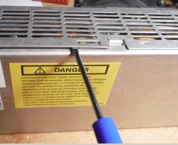
8570 PSU Removal and Cleaning (Built-In Fan)
Remove the standard screw at the front of the PSU. IBM even put a nice
access hole through the drive shelf so you can get to it while the system is
assembled.
Remove the two standard screws at the back [they pull the PSU back onto the
rear of the unit].
With those three standard screws out, the PSU slides out horizontally, off
of the planar power edge connector.
To open, get a security T15 Torx bit (tip is drilled out to mate with pin),
remove the Torx screws. One Torx screw at the upper rear inner side has a
toothed lock washer.
To undo the mating clam shell, note the retaining rib top center. Use a
small screwdriver to get under the sheet metal and pull the halves apart. The
inner cover with the fan pivots on tabs at the lower inner side.
The fan is still connected to a power tap. Pull the cable straight out and
the fan/cover is now free. Put aside.
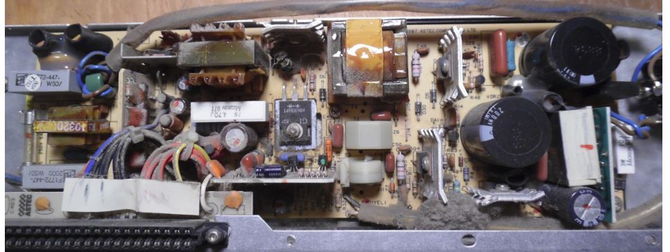
I had a dust bunny about the size of your pinkie, jammed under a cable...
Dust coated about half of the components. Can of cheapo Radio Schlock computer
duster cleaned off the components, although I had to stop and let it warm up
before proceeding...
You can pivot the edge connector out of the bottom edge of the PSU by
SIMMply pulling UP at the rear of it, and then BACK on it.
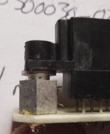
Oddly, the two security T10 screws on the black plastic only seem to tighten
the connector onto the post, leaving the edge connector free to move in four
directions, but it's mounting does not allow it to pull out or be pushed in.
Makes sense, this allows for greater freedom during automated assembly.
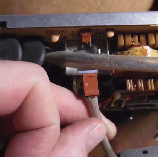
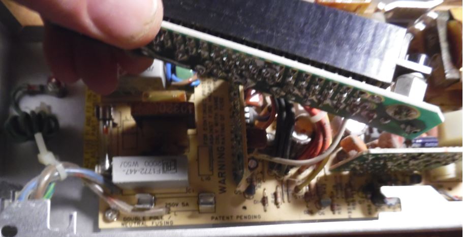
Once you pull the edge connector free, you will see F1 and F2 in the lower
left corner of the PSU PCB (toward the AC socket). The power supply has TWO
fuses, one on the Hot, the other on the Neutral. ASTEC called it "Double Pole /
Neutral Fusing". ASTEC part number is ASTEC 084-00300030-0217. It is a BEL 3AG,
5 A 250 V Fast Blow.
Current BEL product is 3AG 5-R 3AG is a 6x32mm cartridge form.
Datasheet HERE.
8570 / 8550 Bus Riser Power Hack
(from Peter Wendt, original HERE; edited)
You will need:
- a soldering iron (a good one - not one for plumbers!)
- a multimeter with VDC and Ohms-range
- a standard power connector (4 pins - maybe cut from a wrecked power supply)
- a hot-glue pistol with some glue-sticks
- some self-confidence (like always)
It is a good idea to leave the cables on the power connector as long
as possible to make it fit on either direction a hard-disk can be installed
in a Model 50 or 70.
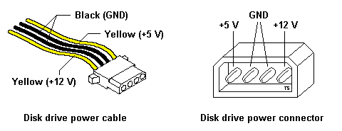
Please note that clone PC power cables use yellow/black/red, while IBM
systems use yellow/black, or red/black/blue. What is important is the position
of the conductor. Note that the drive power connector is keyed with beveled
edges.
Raiser Card FRU 90X1111
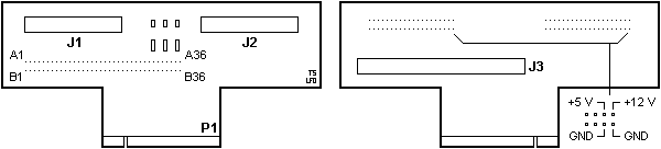
J1 (JN1) Floppy connector #1 (A:)
J2 (JN2) Floppy connector #2 (B:)
J3 DBA-ESDI connector
The three resistor/capacitor pairs on the riser are for DC-buffering and
decoupling. The earlier risers lacked them and once you'd stuffed in 2 FDDs or
1 FDD and a tape problems occurred with loss of data during copying and
suchlike.
What to do:
- remove insulation at the 4 cables from the power connector
(about 2 or
3 mm will do)
- tin-lead them with soldering wire
- solder them to one of the disk-drive connectors (see picture above)
Solder them vertically in the same direction as the pin of the connector
go.
See also Warnings and recommendations further below.
- check for continuity and the absence of short-circuits
(Except: the two black wires are both connected to GND)
- re-assemble everything
- power the system on and leave the fingers on the power switch
- if nothing unusual happens - you're almost through
- if the system won't come up... check everything again!
- Finally, disassemble everything once more and use hot-glue to give the
whole thing stability.
Warnings and recommendations
The maximum power from this hack is about 5 V / 1 A and 12 V / 1 A so if you
have both disk-drives or one disk-drive and a tape streamer installed... it is
probably not a good idea anyway. It will -nonetheless- work in most cases,
until the unit driven over this port doesn't take too much power. Most modern
Hard-disks will not exceed these limits. In case of doubt consult drive manual
for its power consumption. Or don't do the modification.
If you have only one disk-drive installed, take the connector of the second
drive for modification.
Caution! Take care not to damage the tiny connections
on the board near the connector for Drive 2 while soldering the wires.
Remember, that the Model 50 / 70 power supplies aren't that powerful at all.
Especially the Model 50 power supply (94W!!!) is known to have lesser power
than assumed. If you'd already installed a 386/486 upgrade, 64Megs of RAM, SCSI
adapter and a hi-resolution graphic board it will surely collapse.
|