|
As with a journey of a thousand miles, it all begins with the first step..
SRNs with a Procedure Number
of 1, 2, 3, or 7
When a problem is detected with system operation, the Problem
Determination Procedures (PDPs) in the Problem Determination Guide are
used to determine the cause and corrective action. If the PDPs determine
the failure is in the hardware, the system user is given a Service Request
Number (SRN) to record for use.
The SRN is used to determine which FRU is needed to repair the
system. The SRN contains from one to four Service Repair Action (SRA) numbers.
Each SRA number represents a FRU or special repair action.
The Problem Isolation Charts (PICs) in Section 3 use the
SRA numbers to isolate the failure to a failing FRU. Appendix B contains
an SRA to FRU Cross-Reference List to provide you the part number of the
failing FRU.
An SRN always contains a Source Number and at least one
SRA.
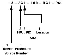
SRN Example

Source Number
The left two digits of the SRN is the source number. The
left digit (1 in the example) is the device. The right digit of the source
number is the procedure that produced the SRN.
Device
Procedure
1 - System unit
1 - Resident POST program
2 - Display
2 - Loadable POST program
3 - Keyboard
3 - Standalone diagnostic program
4 - Tape drive
4 - Licensed program product
5 - Printer
5 - Support center
6 - Plotter
6 - Problem determination procedure
7 - Expansion unit
7 - Device not found when diagnostic
programs loaded
8 - Mouse
8 - Reserved
9 - Attached communications 9 - Reserved
device
0 - Reserved
0 - Reserved
A - Tablet
B - Dials Feature
C - LPFK Feature
E - Portable disk drive
Source Repair Action Number
The three digit groups make up the SRA numbers. The left
two digits of the SRA number is the FRU / PIC code (23 in the example).
The right digit of the SRA number is the location number.
FRU / PIC code
Location
See SRA# Chart 1 - Adapter
slot 1
or App B
2 - Adapter slot 2
3 - Adapter slot 3
4 - Adapter slot 4
5 - Adapter slot 5
6 - Adapter slot 6
7 - Adapter slot 7
8 - Adapter slot 8
9 - Reserved
0 - System board
A through R - Identifies system board slots,
drive positions, switch banks, or
memory module positions.
|