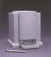
Skynet SNP-6033 Layout
Skynet SNP-6033 Power Connector Pinouts
Serial Port Configuration
Setting Com Port and Baud Rate
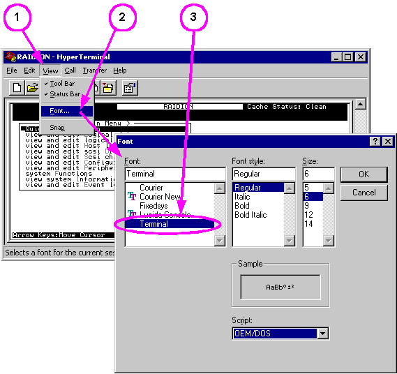
Setting Font and Font Size
Select VT-100 Terminal
VT-100 Main Menu
RAIDION LTX Controller PCB
RAIDION LTX Controller PCB Power and SCSI ID
Beep and LED codes for RAIDION Gandiva
Beep Codes
LED Codes
CPU Exception LED codes
Orientation of Hard Drive SCSI ID Header
Gandiva Codesets (Firmware)
Gandiva Multimedia Codeset
Multimedia caching scheme
Gandiva Transaction Codeset
Transaction caching scheme
RAIDION (Gandiva) Disk Arrays:
2T43.exe Transaction code, version 2T43
2M43.exe Multimedia code, version 2M43
RAIDION LTX (Gandiva): Uses the RAIDION plus manual. Most
information is equivalent less the Ethernet port and battery
backup.
Desktop version:
Book 1 - Introduction and General Information (1.8MB)
Book 2 - Hardware Installation and Configuration (6.7MB)
Book 3 - Utilities for use with LCD/Keypad or terminal (7.4MB)
Book 4 - System messages and troubleshooting (2.2MB)
Book 5 - Array Management utility for use with Windows (6.4MB)
Note: The Internet Archive links point to a dufus
"Sale on Storage Containers" page. These files might be lost for all time.
If you happen to have these files, please
Contact Us
Beep and LED codes for
RAIDION Gandiva
Multimedia vs.
Transaction Code
Serial Port Configuration
G181 error message decoder
G181 Unusual State W X Y Z 0 0 0 0
G6 error message decoder
G6 Device error at channel aa ID bb: Status xx/yy/zz cc dd eeeeeeee
Cache Memory One
pair of standard 72 pin, 60 ns, Parity SIMMs 4 MB, 8 MB, 16 MB, 32 MB
or 64 MB.
Simple, Scalable RAID
(BYTE Feb 1995; Raidion LTX array, Micropolis Gandiva RAID controller)
Power Switch?
There is NO power switch on the RAIDION LTX (Gandiva). Unsettling.
Skynet SNP-6033 Layout

IC1 Sharp PC111
IC2 SK-8085
F1 BEL 5MF 2A / 250v
IC1 Sharp PC111 Long
Creepage Distance Type Photocoupler Datasheet
Skynet SNP-6033 Power Connector Pinouts

Serial
Port Configuration
All typical RAID setup and configuration can be done using the
LCD/Keypad, a serial port connection is not required. Using a
null modem serial cable, connect RAIDION LTX COM1 (DE9) to a COM
port on the PC or Laptop, start Hyperterm and configure.
Setting
Com Port and Baud Rate: (Illustration from
RAIDION U2W (Ultra2 / LVD) class products, use 9600 on Gandiva)
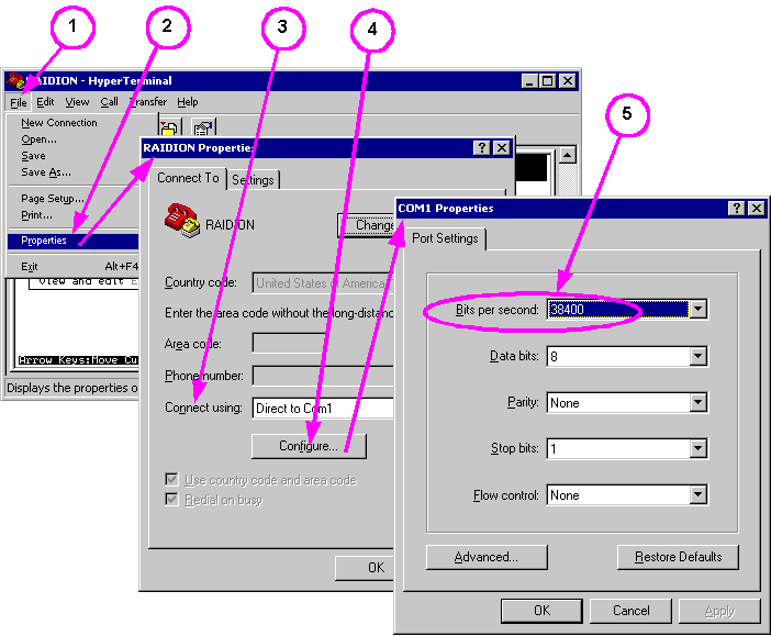
Terminal Emulation: 9600 Baud, No Parity, 8 Data Bits, 1 Stop
Bit, Half Duplex (Full Duplex w/firmware 2t43), No Flow Control.
Setting
Font and Font Size:
Select
VT-100 Terminal
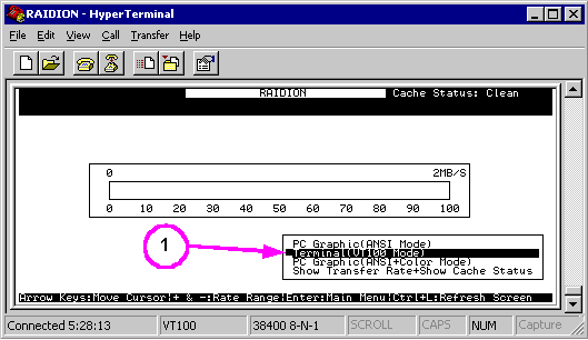
Use Up or Down Arrow keys to select Terminal (VT 100 Mode),
press Enter, Main Menu should pop up and look like this:
VT-100
Main Menu
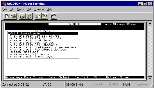
Save configuration. Click on File | Save | ... You can now
use Hyperterm to configure and maintain RAIDION array.
Operation:
When both serial port and terminal emulation are configured,
press Escape key to 'wake up' serial port. A menu should
be presented with the same structure in terminal mode as that
with LCD/Keypad operation.
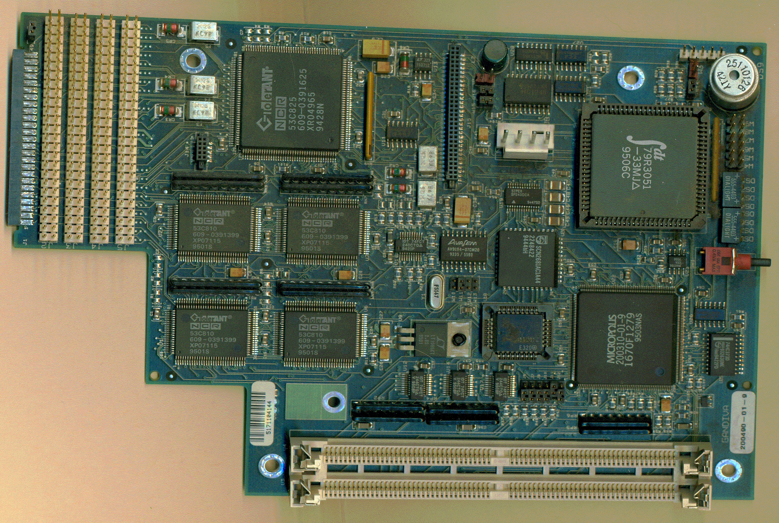
RAIDION LTX Controller PCB 200661 Rev A / 200490-01-9
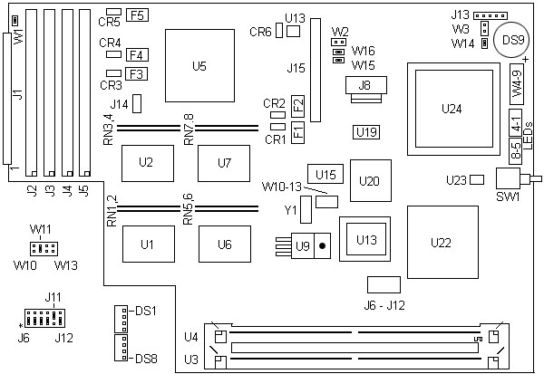
CR1 Termpower diode for
F1
CR2 Termpower diode
for F2
CR3 Termpower diode
for F3
CR4 Termpower diode
for F4
CR5 Termpower diode
for F5
CR6 Diode next to
U13, LT 329
DS1-4 Dialight
555-4403 Right
DS5-8 Dialight 555-4403 Left
DS9 25110126 beeper 421Y
F1-4 125 PTCs, one
per 53C810 termpwr line
F5 125 PTC,
termpower line for 83C825
J1 50 pin header for
LCD panel and serial port
J2 SCSI Channel 3
J3 SCSI Channel 2
J4 SCSI Channel 1
J5 SCSI Channel 0
J6-12 unk, J6-10 and
J12 jumpered 1-2
J8 4 pin power
J11 unk, jumpered
2-3
J13 SCSI ID switch
J14-15 headers for
battery backup???
RN 1,2 Termpacks for U1
RN3,4 Termpacks for U2
RN5,6 Termpacks for U6
|
RN7,8 Termpacks
for U7
SW1 C&K EP11,
0.4VA reset
U1,2,6,7 NCR 53C810
(one per channel)
U3,4 72 pin FPM SIMM
U5 NCR 83C825 (all
SCSI channels)
U9 LT 1086CT 2.5
U13
LT 329
U15 AvayaSem AV9194-07CW20
U18 AM29F040-120J
for firmware
U19 Sipex SP241CCA
U20 Phillips
SCN2681AC1A44
U22 Micropolis
200310-01-9
U23 Maxim 706
U24 Idt
79R3051-33MJ
W2 unk, open
W3 unk, open
W4-9 unk
W8 2 pin header,
activity LED
W10-13 unk
W14 Unk, jumpered
W15 Unk, jumpered
W16 Unk, jumpered
Y1 F147 xtal
|
RN1-8 10 pin SIPP resistor
packs, A11GA 433, I'd guess bussed 4.3k ohm
SW1 Nice little C&K
normally open SPST? switch, EP11, 0.4VA reset, I bet
U22 Micropolis 200310-01-9
ASIC for calculating checksums
DS1-4,5-8 Dialight 555-4403
2mm LED CBI Circuit Board Indicator Yellow 5V
U1,2,6,7 NCR 53C810 PCI-SCSI
I/O Processor Data Manual
U15 AvayaSem AV9194-07CW20
datasheet
U19 Sipex SP241CCA datasheet
U20 Phillips SCN2681
Datasheet
U23 Maxim 706 μP supervisory
circuit
U24 IDT79R3051 RISC
Controller Datasheet
RAIDION
LTX Controller PCB Power and SCSI ID
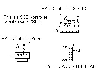
J13 is attached to the SCSI
ID switch on the front of the module.
W8 is attached to the 2 wire
header that attaches to the activity LED on the module
Note: The red
wire goes to the front pin, see the "+" on the drawing?
J8 has only two pins
connected, Red, N/C, Black, N/C
This may seem odd, but the Gandiva needs to be set to a SCSI ID
that does not conflict with the adapter it is connected to.
Example, if you have a Corvette at SCSI ID 7, you CANNOT set the
Gandiva RAID module (bottom module) to the same SCSI ID of
7...Hilarity ensues... My SWAG is the four SCSI channels are
internal to the LTX, and are NOT considered when choosing a SCSI
ID for the LTX...
I wonder if this will do PUN/LUNs, something I have never
worried about with only SCSI devices on the chain, never SCSI
controllers in their own right...
Beep and LED codes for
RAIDION Gandiva (DS8 is on left, DS1 is on
right... )
Beep Codes:
Test description beep sequence (upon error) (DS9 beeper)
CPU
Test
Short Short Short Long
Timer
Test
Short Short Long Short
ROM
Checksum
Short Short Long Long
RAM
Sizing
Short Long Short Short
Ram
Test-Bank0
Short Long Short Long
Ram
Test-Bank1
Short Long Long Short
DUART
Test
Short Long Long Long
Host SCSI
Ports
Long Short Short Short
PCI Bus
Test
Long Short Short Long
ASIC
Test
Long Short Long Short
Parity
Error
Long Short Long Long
Illegal Config
Error Long
Long Short Short
CPU
Exception
Long Long Short Long (see LED
code below)
BBU SIMMS
okay
Long Long Long Short
LED Codes:
DS8 DS7 DS6 DS5 DS4 DS3
DS2 DS1
CPU
Test
ON ON ON ON
ON ON ON ON
Timer
Test
ON ON ON ON
ON ON ON off
ROM
Checksum
ON ON ON ON
ON ON off ON
RAM Sizing and RAM
Test
ON ON ON ON
ON off ON ON
DUART
Test
ON ON ON ON
off ON ON ON
Host and Device SCSI
Ports ON
ON ON off ON
ON ON ON
PCI Bus
Test
ON ON off ON
ON ON ON ON
ASIC
Test
ON off ON ON
ON ON ON ON
All Tests
COMPLETE
off off off off off off
off off
CPU
Exception LED codes. Applies only with CPU
Exception beep code (Long, Long, Short, Long)
Test
Description
DS4 DS3 DS2 DS1
Address Error Exception
(Load)
off ON off off
Address Error Exception
(Store)
off ON off ON
Bus Error Exception (Instr.
Fetch) off ON
ON off
Bus Error Exception (Data Load/Store)
off ON ON ON
SysCall
Exception
ON off off off
Break
Exception
ON off off ON
Reserved Instruction
Exception
ON off ON off
Co-Processor Unusable
Exception
ON off ON ON
Arithmetic Overflow
Exception
ON ON off off
Orientation of
Hard Drive SCSI ID Header
At first I was a bit mystified, but Micropolis used only four
wires instead of six.
Rotate the six position header so that the side with one wire is
to the bottom, for it is a common ground. The colored wire on
the SCSI ID header is the common ground. For the 0662, the
colored wire is on the right as you look at the drive from the
front.
4 2 1
O O O
- - O <--- colored wire is
ground
Gandiva Codesets
(Firmware)
How do I find out what version I am currently using?
Use LCD/Keypad, press Cancel key a few times to bring display
back to top of menu if not already there. Gandiva version level
will be located next to the RAIDUTIL label.
Gandiva Multimedia
Codeset
2M43.exe Gandiva Multimedia Codeset
Multimedia
caching scheme
Use with host applications which issue Read/Write
requests of sizes 64KB or larger to the Gandiva. The advantage
is even greater if:
Attendant stripe size for Gandiva is large- 64 or
128 blocks.
Requests from host are predominantly sequential.
Queue depth for host requests to Gandiva is
small- preferably 1.
Only one host process is accessing Gandiva for
block I/O.
Still not sure,
then use 2T43.
Note: Not [every] any
Multimedia application will benefit from the Multimedia
codeset. Some Multimedia programs generate Reads and Writes of
modest sizes (64 blocks or less), which would find the
Transaction caching scheme more suitable for their purposes.
Gandiva Transaction Codeset
2T43.exe Gandiva Transaction Codeset
Transaction caching scheme
Generally, hosts which generate small- and medium-sized file
I/O, and frequent file-system updates (e.g., most network
servers and database systems) are likely to benefit from the
transaction codeset. The Gandiva request sizes are typically
in the 2KB-to-32KB range. Use of the Multimedia codeset in
such a scenario will only produce overheads in finding memory
resources to process the hosts requests, resulting in the host
perceiving lower data- transfer rates than expected, and
commands taking longer to complete.
Usually, multi-user and multi-process systems will find the
Gandiva's Transaction Codeset to be a better performer, as
they tend to generate random I/O and more frequent commands
(especially if the host adapter in the system is making use of
the SCSI command-tagging feature).
The stripe-size setting on the array, which is also a factor
in the overall performance, is usually small for on-line
transaction processing (OLTP) applications- the default of 8
blocks or 16 blocks.
The files are self extracting, they include instructions, ASPI
drivers for Adaptec Host Adapters and the DOS download utility
raidutil.exe (bootable DOS floppy method). Check the utilities
page for other download tools via Novell, Windows 95, and
Windows NT.
Gandiva Cache Memory
The RAIDION LTX (Gandiva) can accommodate one pair of standard
72 pins SIMM (parity 72-pin, 60 ns, 4, 8, 16, 32 or 64 MB) as
Cache Memory. Both pair must be of the same size
SIMM. This provides from 8MB to 128MB of total Cache
Memory.
My Gandiva came with a pair of "Lite On" 1036D SIMMs.
The most ideal Cache Memory size is 32MB. Larger Cache
Memory size does not improve performance any further.
Identify Cache Memory size: Serial port, System
Information section via Statistics > System
Information. You can't use the LCD/Keypad.
Battery Backup: The LTX (Gandiva) does not have and can not
use the battery backup SIMMs.
Access to SIMM sockets: The controller module must be removed
from its plastic housing for desk top towers.
On the Gandiva, the entire top cover must be removed to access
the SIMM. Cut the warranty seal is done at your own risk.
RAID configuration information is stored on the disk modules,
not on the SIMMs. So don't worry about loosing your RAID
configuration when changing the SIMMs. But as always,
you should backup your data before attempting any changes to
the RAID.
|