|
@8EFF.ADF IBM PS/2 SCSI Adapter w/Cache
C8EFF.ADF Init file for @8EFF.ADF
190-057 IBM Personal System/2 Micro Channel SCSI Adapter with Cache (summary only)
192-067 IBM PS/2 Micro Channel SCSI Adapter with Cache (redesigned version, "Spock Prime")
tribltst.zip OEM SCSI - Tribble Card Test, 10/06/1992 (thx John Horvath)
![[P]](/other/img/photo.gif)
Caution! This bootable disk may destroy all data on your hard drive without warning!
Contains SCSITST.EXE - SCSI Interface Card Test Program v2.03. (for Tribble & Spock)
SPOCK206 IBM SCSI Driver for Windows 95/98 and Windows NT by Unal Z
scsi_spock.c 86Box emulator - Implementation of the IBM PS/2 SCSI controller w/ cache
Testing SIMMs for 2MB upgrade
Extending Cache Memory (from Alfred)
Narrow IBM SCSI (architecture and implementation info)
SCSI /A and SCSI w/Cache MCA Pinout Comparison
Japanese SCSI A/32 Adapters (short alternatives to "Spock")
Adaptec's Disk Controller Sets SCSI Speed Record (AIC-6250 article)
SCSI w/ Cache - Old
SCSI w/ Cache - Old w/ Newer PCB
SCSI w/ Cache - Newer
SCSI w/ Cache - Newest
Diagnostic Port
Specifications
Block Diagram
Adapter Firmware
New BIOS Benefits
Swapping BIOS chips for >1GB Support
Autotermination Capability- Yellow vs. Orange Termpacks
Terminator Resistance Values
Termpack FRU
Results from upgrading to 2MB cache
Installing 2MB
Non-Compatible SIMM Results
Converting Standard 30-Pin SIMMs
8MB Cache Hack?
Component Level Diags and Error Codes
ADF Sections
SCSI w/ Cache - Old
"Spock" (single osc.) FRU P/N 84F8014, FCC ID ANO6451018
|
F2 PTC fuse
J300 C60 External SCSI Port
T-RES Term. resistor pack
U32 80C188 10 MHz MCU
U44 32Kx8 SRAM (U32 MCU)
U47 SCSI microcode 64F5984
U48 15F7917
U68 SCSI BIOS Even
|
U69 SCSI BIOS Odd
U70 15F6903 SCSI Cache/data flow controller
U73 Adaptec AIC-6250EL
U79 33F6715 SCSI MCA iface/BM DMA controller
U87,88 30-pin SIMM socket
Y1 20.0 MHz osc
(SER) Pads for 3+1-pin diagnostic header
|
U44
HM62256LFP-12T,
SRM20256LM12,
M51257AL-12, or compatible 32Kx8
SRAM. Used as RAM for the 80C188 MCU (U32).
(SER) Pads for diagnostic header. 3 pins
+ 1 key (left to right): TXD, GND, KEY, RXD. The port can be used to access the
Serial Console.
Pin 1 of the internal SCSI edge connector is on the solder side, pin 2 on
the component side.
This adapter has no internal termination resistor or autotermination
circuitry and needs an external bus terminator. The adapter needs the update
SCSI BIOS P/N 92F2244 / 92F2245 in order to handle drives >1GB.
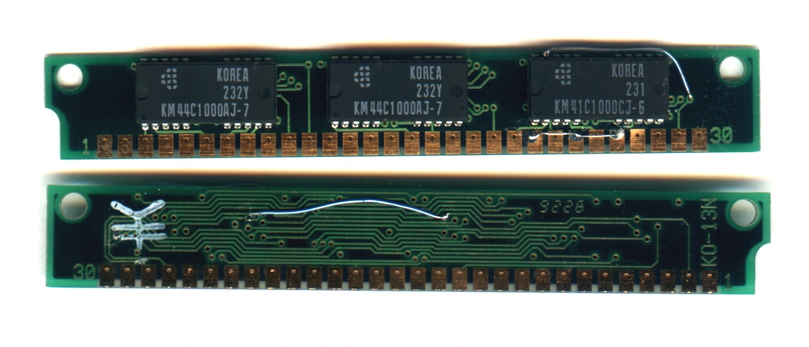
SCSI w/ Cache - Old w/ Newer PCB
"Spock" (single osc.) FRU P/N 84F8014, FCC ID ANO6451018
|
Some single oscillator adapters 6451018 use the later "two oscillator" PCB,
but only have the 20 MHz (Y1) oscillator populated.

The components are the same as on the "old" single oscillator "Spock". There
are some bodge wires in the mid-section of the board.
For more information see the Old SCSI w/ Cache.
SCSI w/ Cache - Newer
"Spock" (dual osc.) FCC ID ANO6451018
F2 PTC fuse
J300 C60 External SCSI Port
T-RES Term. resistor pack
U32 80C188 10 MHz MCU
U44 32Kx8 SRAM (U32 MCU)
U47 SCSI microcode 33F5546
U48 15F7917
U68 SCSI BIOS Even
|
U69 SCSI BIOS Odd
U70 15F6903 SCSI Cache/data flow controller
U73 Adaptec AIC-6250EL
U79 33F6715 SCSI MCA iface/BM DMA controller
U87,88 30-pin SIMM socket
Y1 20.0 MHz osc
Y2 25 MHz osc
(SER) Pads for 3+1-pin diagnostic header
|
For more information see the Old SCSI w/ Cache.
SCSI w/ Cache - Newest
"Spock Prime" (triple osc.) FRU P/N 85F0063, FCC ID ANOSPRIME
|
F2 PTC fuse
J300 C60 External SCSI Port
T-RES Term. resistor pack
U32 80C188 16 MHz
U33 84F8324 SCSI bus controller
U44 32Kx8 SRAM (U32 MCU)
U47 SCSI microcode 61G2976
U68 SCSI BIOS Even
|
U69 SCSI BIOS Odd
U70 15F6903 SCSI Cache/data flow controller
U79 33F6715 SCSI MCA iface/BM DMA controller
U87,88 30-pin SIMM socket
Y1 20.000 MHz osc (U33)
Y2 25.0000 MHz osc (U70 & U79)
Y3 32.0000 MHz osc (U32 MCU)
|
The "latest" cached SCSI, FRU P/N 85F0063, has no Adaptec chip present and a
larger yellow 20-pin DIL terminator chip close to the external port. This
adapter is significantly faster than the "old" adapter.
Diagnostic Port
Double sided 2 x 5-pin card-edge connector:
| Pin | Signal | Pin | Signal |
|---|
| C01 | Ground | C02 | RXD |
| C03 | +5 V | C04 | TXD |
|
| C05 | Ground | C06 | CHRESET |
| C07 | +5 V | C08 | BURNIN |
| C09 | Ground | C10 | ITS |
Odd pins C01 - C09 are on the solder side, even pins C02 - C10 on the
component side. There is a physical key between pins C03 and C05 (C04 and
C06).
The port can be used to access the
Serial Console.
Specifications
The IBM SCSI adapter is 8-bit narrow, single-ended SCSI with SCSI-2 style
command set and SCSI-1 speed of 5 MB/s. It can handle 7 Fast- or Ultra-SCSI
devices and can handle even 7 Wide-devices if there are converters used from
Wide-to-narrow SCSI (68-to-50 pin) but these devices must use device numbers
from 0 - 6. The SCSI-ID 7 is used for the controller itself. First device on
IBM SCSI controllers is the one with the highest ID (6) opposed to Adaptec or
Buslogic controllers which boot from ID (0) or (1). It can handle even
Ultra-SCSI drives, because SCSI is compatible in any directions - other than
shit-IDE.
These SCSI adapters have a single bus that provides both internal and
external SCSI bus connectors. For these adapters, devices are logically ordered
depending only on adapter slot number and the SCSI IDs of the devices.
Note: IBM SCSI adapters that use a SCSI BIOS
earlier than the 92F2244 / 92F2245 pair will require the IML drive to be SCSI
ID6.
The SCSI w/Cache is a "Single Ended" SCSI controller, which means that every
signal has GND as return line. The other relevant SCSI standard of
"Differential" means, that every signal has a return line with inversed
polarity ... when -for example- +DATA0 sends a logical "1" on the active line
the return line -DATA0 sends a logical "0". The transceiver circuit in the
device checks the *difference* between the two signals (therefore
"differential") - line disturbances afflict both lines at once and are
eliminated therefore.
| SCSI type |
SCSI-1 w/SCSI-2 commands |
| SCSI bus path / speed |
8 bit / 5 MB/s |
| I/O bus path / speed |
32 bit / ? MB/s, 16.6 MB/s burst |
| I/O features |
N/A |
| RAID levels |
None (use software) |
| Tagged Command Queuing |
No |
| SCSI w/cache CPU |
80C188 @ 10 MHz (old) or 16 MHz (new) |
| Adapter Size |
Type 3 (long) |
| SCSI Channels |
One (internal/external) |
| Connectors |
One internal; one external |
| Devices supported |
7 devices per adapter |
| Cache std / max |
512 KB / 2MB |
| Cache method |
Two 30 pin SIMMs |
| Cache configurations |
0, 512K, 2MB |
| Cache write policy |
Write-through |
Block Diagram
Components:
- Cache and Data Flow Controller - 15F6903 (U70)
- System Interface/Bus Master DMA Controller - 33F6715 (U79)
- SCSI Bus Controller - Adaptec AIC-6250EL (U73) or 84F8324 (U33)
- Microprocessor - 80C188 MCU (U32)
- ROM - 27C512 (U47) w/ SCSI microcode for the microprocessor
- RAM - 32Kx8 SRAM (U44) -
HM62256LFP-12T,
SRM20256LM12,
M51257AL-12, or compat.
- Disk Cache Buffer - 2x 30-pin parity SIMM (U87 & U88)
- SCSI BIOS - 2x 27C256 (U68 & U69)
- 32-bit Micro Channel - 32-bit data bus & 32-bit address bus to the host
- 50-pin Internal SCSI Bus Connector - card edge (same bus as external)
- 60-pin External SCSI Bus Connector - MCX connector (same bus as internal)
Further information about the narrow IBM SCSI subsystem can be found
HERE.
Adapter Firmware
See also HERE.
Firmware
U47 - 27C512 Original on ST M27C512 -12F1 Use any 27512 equivalent.
BIOS
SCSI BIOS 92F2244 1991, for PS/2 Caching SCSI controller, 27C256
SCSI BIOS 92F2245 1991, for PS/2 Caching SCSI controller, 27C256
SCSI BIOS 64F4376 1990 (Old Spock)
SCSI BIOS 64F4377 1990 (Old Spock)
33F5546 reports itself internally as 33F5547
Microcode Differences
From Charles Lasitter:
With the triple oscillator (newest) versions of the Enhanced
SCSI w/cache, I see some Microcode differences but don't see much in the
way of any particular pattern for when one Microcode will be in use versus
another.
One adapter has 10G4890 dated 1991. Another has 61G2976
dated 1993. What is the difference between these two microcodes?
I invariably see the "1993" microcode with some unusual looking cache SIMMs,
but changing them doesn't seem to make a difference. I see "1993" on some
boards labeled as "CARD 1" and others" CARD 3". There is nothing
I can track there.
I can't figure out why they would change it if they didn't
make something better, but I don't know what that would be or how it would
manifest itself. I know that the microcode from triple oscillator adapters
can't be switched to the old unterminated adapters, but I'm uncertain about
from one two another for the same "3-oscillator" family.
From Tony Ingenoso:
(guessing) There may have been a change to deal with the low-power
mode problems of certain microcode level Kazuza series drives... Had to tweak
the heads off the cylinder they were idled over to keep from losing data when
the next write (after power restoration) happened to be on that cylinder...
nasty problem...OS/2 had an ABIOS patch to deal with it on the pseudo-ESDI
versions of the drive.
New BIOS Benefits (From Tim Clarke)
The upgrade provides the following additional capabilities:
- More efficient use of Adapter ROM memory - minimizes adapter configuration
conflicts.
- BIOS support for fixed disks up to 3.94 gigabytes per device.
- Supports "Search IML" from any PUN (Physical Unit Number) or SCSI ID.
The system partition is no longer restricted to only SCSI ID=6.
Each fixed disk ID will be searched for a valid system partition.
- Allows redundant system partitions (IML).
- Sharing of SCSI devices. An external SCSI device, such as the 3511,
may be shared between two system units. The menu item is "Target"
Multiple, redundant partitions are useful if drive id. 6 fails. 'Recovery'
can be automatic without partially ripping the machine down to change SCSI
Id.s. You do, however, need to have planned for this and set up the appropriate
'IML/Reference Partition'(s) and 'Active Partition'(s) on the 'fallback' drives
(Id. 5, 4, 3... etc.)
Swapping BIOS chips for >1GB Support
From Peter Wendt:
Today - while juggling around with parts & cards on a Model 90
- I decided by what reason to remove the SCSI-BIOS from an old uncached SCSI
and stuff that from the "later" cached on it. Earlier this year I'd tried to
swap the entire EPROM sets among the old and the later cached - and it did not
work. Today I left the busmaster microcode EPROM on the card and only swapped
the SCSI-BIOS.
To my undescribeable surprise: it worked. To make sure that it is not a
gimmick of that machines' BIOS I tried it on a Mod. 70-A21, which has
definitely no enhanced SCSI-BIOS support in the planar microcode. I pulled the
2GB IBM 0664 harddisk from my WinNT Server and installed it in the Mod. 70. I
have a heavily modified Mod. 70 - has a standard power-plug (as described on my
page, folks !) and a Kingston 486DX-33 upgrade. I also installed the uncached
SCSI with the old EPROMs. No surprise: "No operating system" and the system
halted.
Then I used the 92F2244 and 92F2245 on that same adapter ... Voilà:
"OS Loader V4.00 ..." and WinNT 4.0 Server started up ... ! (Ever seen that on
a Mod. 70 ?) Tried the same procedure with the old IBM SCSI adapter with cache
(the one *with* the AIC-6250EL Line Interface) - with the same results. Old
BIOS-chips: No operating system - New chips: Win NT starts.
Conclusion: If you have one of the older SCSI-Adapter *cards* you can use
the SCSI-BIOS from the later-level SCSI Adapter with cache to make the system
capable to handle drives over 1GB.
I do *not* know if there is another limit after 4GB - but assume it is (I
don't have drives over 2.2GB currently). This limitation will at least exist on
the IML-machines, since the principle that starts up the IML cannot handle
drives over 3.94GB (the mysterious IML-border) due to the technical method of
putting the system partition MBR at *the end* of the physical diskspace. The
register width is obviously limited to any number of total data-blocks below
4GB. So that does not change at all.
ECA 032 Possible Replacement Required
The old adapter w/cache can be identified by PN 64F1333 on module U47 (just
below the MMKs). If you have this adapter, replace it.
Ed. I saw something about potential data loss
concerning this ECA. Not sure- my U47 is the adapter BIOS.
Making Your Own IBM Cable
The actual cable itself is a standard SCSI-1 cable. The unusual part is the
50 pin edgecard connector. Note that Pin 1 on the adapter is towards the
mounting bracket. Remove the 50 pin dual row header (pry it open or cut it off)
and crimp on the 50 pin edgecard connector. Watch pin 1!
Note: On original IBM ribbon cables, the cable exits
the edgecard connector TO THE LEFT as the connector is seated on the internal
port. As installed, this means the cable goes straight up towards the top of
the 95 case and away from other adapters. This makes it possible to route it
away from them towards the front of the case, then down the site of the DASD
structure, then to the drives.
Autotermination Capable Adapters or Planars
If the card or planar has a red colored T-Res, it does not have the
circuitry to support autotermination (you have to pull the termpack if you add
an external device). If the termpack is yellow, then the additional circuitry
exists and you can add or remove external devices without having to pull the
T-Res off the adapter.
> Peter, for the $64,000 Question. If you use a yellow termpack on a
adapter or board that had a red one initially, will that enable it to
autoterminate?
Definitely: Not. The "Auto-Terminate" is a function that require a little
more hardware: a switching transistor that disables the TermPwr wire from the
T-RES and another transistor / IC function that senses the voltage on the
TermPwr line and the voltage on the data lines to figure out whether the line
is terminated or not.
Terminator Resistance Values
Bourns 4120R Series
Bourns 4120R-003, -221/331 Model (41 = Molded DIP), 20 Pins, R = Thick Film Low Profile, 003 =
Dual Terminator. Resistance Code in the format R1 / R2, First 2 digits
are significant, Third digit represents the number of zeros to follow. 220
ohm, 330 ohm.
It looks like this:
Termpack FRU
From Tim Clarke:
AFAIK, there is only one FRU for the "internal" termination
resistor pack for the IBM SCSI w/cache (adapter FRU 85F0063) that has the
appropriate 20-pin socket and the IBM SCSI w/o cache (adapter FRU 85F0002). The
termination resistor pack (20-pin) is FRU 57F2870 and, provided you insert it
with Pin 1 correctly oriented, should work O.K.
Some Other Thoughts
From Charles Lasitter:
I've had some VERY entertaining results in my installations,
depending on what other drives were present, and which version of the
processor BIOS was used.
With the 52G9509 in place, ID6 in bottom bay (Mod 95) at
end of cable, ID5 in bay above on next spot on cable, I couldn't get the
IML to go to ID6 to save my ass. It made a beeline for ID5 every time.
Put in the old BIOS, and it goes straight for ID6.
I think there are a LOT of quirks like this (and yours)
to be mapped out, and that seemingly innocuous settings changes in the ABIOS
make differences you'd never guess sometimes.
I also suspect that the Mod 90 is it's very own distinct
bird with it's own eccentricities in this and related matters.
If replacing the earlier version adapter with the new version, the
following problems may be encountered on fixed disks larger than 1
Gigabyte.
a. Non-IML systems with Fixed Disk "C" greater than 1 Gigabyte, formatted
/S with the early version SCSI adapter with cache (old version of BIOS)
will experience "Unable To Boot Operating System" message. This is because
the IBMBIO.COM and IBMDOS.COM (hidden files) are placed in absolute
positions on the Fixed Disk, not relative. If a boot from a DOS diskette
is done, Drive "C" is still accessible. A backup of the Fixed Disk should
be done, then a low-level Format, followed by an operating system format.
This will reorganise the Fixed Disk with the new version BIOS on the new
SCSI adapter.
b. Full capacity of greater than 1 Gigabyte will not be accessible on
Fixed Disks which were originally attached to the old version SCSI adapter
with Cache until the Fixed Disk is operating system formatted, (DOS, OS/2,
etc) by the new version adapter (new BIOS code).
2MB SCSI w/cache
Increasing the cache to 2MB
One module that can be used to expand the IBM SCSI Adapter with cache /A
from 512K cache to 2MB cache is the IBM P/N 30F5360 / FRU 74X8637, which is a
1MB x 9 bit (Parity) 100 ns module *with* IBM-specific presence detection.
These IBM modules are in the Mod. 30-286 (8530-Hxx or -Bxx) with 80286 CPU - if
anywhere at all.
My 1 MB SIMMs are marked MSC2314-12YS9A 183004 68X5721.
It has 9 OKI M511000A-1AJ chips, mnf. 89335521
Kingston modules labeled KTM-1000/M30 (From Peter)
From Jerry Dumer:
I have 3 boards with Toshiba THM91010AS-10 SIMMs that do the job
fine. I found these on a memory card in a Model 60. They are gold pins. I
imagine Toshiba made them for the 30-286s. They do work.
Trying Non-Compatible SIMMs
If you try some likely looking 30 pin SIMMs and they don't have the correct
CAS/RAS wiring, the system will disable them it and you will see SCSI Adapter
w/Cache with 0KB. Don't freak out. Replace the original SIMMs and run Advanced
Diags and test the SCSI Adapter to restore your 512K cache. Been there, done
that.
Converting Industry Standard Memory
Yes. Alfred Arnold has finally figured it out. Dr. Jim
Shorney confirms this triumph. The biggest hurdle was the IBM modules have
a different RAS/CAS scheme in addition to the different pin-out. As time
goes on, exceptions MAY be found. News as it happens.
Alfred's 30-pin SIMM Hack
(original HERE)
For those that have the burden of college education, I made some
assumptions. First, the SIMM pins will always be performing the same function
(like parity Data Out, parity CAS). Second, those SIMM pins can be used to
positively identify the parity chip's DO and CAS pins.
This makes manufacturer's data sheets unnecessary. Assuming
they even have them.
- Break connection between SIMM pin 26 and parity chip's DataOut
pin; This inferrs that SIMM pin 26 goes to Data Out-
- Connect parity chip's DataOut pin to SIMM pin 29
- Tie parity chip's lead that USED to go to SIMM pin 26 to SIMM pin 29
- Break connection between SIMM pin 28 and the parity chip's CAS pin
- Parity chip CAS is attached to SIMM pin 28
- Connect parity chip's CAS pin to SIMM pin 2
- Attach lead that used to go to SIMM pin 28 to SIMM pin pin 2
- Connect both SIMM pins 26 and 24 to SIMM pin 22 (GND).
- Tie SIMM 26 and 24 off to SIMM 22
A picture of Dr. Jim's 2MB Hack.
8MB Hack?
Peter says:
No. It is a little miracle that the 1MB modules work
for the 2MB total cache, but the 4 Meggers are -again- different to the
1MB ... apart from the presence detection and the RAS/CAS scheme. There are
1MB modules that behave the same way than the 256K modules - but no 4MB.
The 4MB you find are either Industrial Parity (9 bit, but
w.o. presence detect) or non-Parity Industrial modules (8-bit). IBM itself
never introduced 4MB modules of that scheme for their own machines. The
PS/VP Series 1 used 1 and 4MB 30-pin modules, but these were "industrial
standard" modules.
The PS/2 256K, 512K and 1MB modules are very unique. They
depend -technically- on a very old (1985) Hitachi patent to which IBM only
added the presence detection. From the principle the "Single RAS" scheme
of these modules is similar to the Hitachi HB61009BR-15, 150 ns module -
a very antique construct, which were superseeded by the much more common
HB41256-style design, which uses separate RAS/CAS timing for interlaced access
to the cell-array, which then allows much faster RAM access (typically 100
- 60 ns).
Results of upgrading (by Peter Wendt)
The IBM Adapters with and without cache /A are in fact SCSI-1 adapters with
5MB/s interface speed (!) to the device. This however does not tell how high
the effective data-throughput might be.
This depends on more factors than just the interface-speed:
- speed of the drive mechanism (track-to-track / average seek)
- adapter-cache (size, speed and degree of optimizing)
- device-cache (size / usage)
- cable and degree of disturbances through line noise / spikes etc.
- termination (reflection of data packets)
- adapter and device cmd set (autonomy of device / command queing)
- the adapters chipset
Okay - for the curiousity: I have tested the 2MB-cache in my 8595-AK9 (32MB
RAM / Kingston TurboChip / modified BIOS) with 2 different IBM adapters and a
Quantum Fireball TM2110S (2.1GB Ultra-SCSI). This drive is known as quite fast
and should not be the bottle-neck. I used the IBM SCSI adapter with cache /A in
the version *without* the internal termination resistor and the Adaptec AIC
Line interface chip (IBM old) and I used the IBM SCSI Adapter with cache /A
*with* the internal yellow termination resistor and the IBM SCSI Interface (IBM
new).
Here are some test-samples (results are temporary examples).
Results for old SCSI w/cache
| |
512KB cache |
2MB cache |
Change (%) |
| Minimum (KB/s) |
28.8 |
28.9 |
+ 0.3 |
| Weighted Average (KB/s) |
796.4 |
874.8 |
+ 9.8 |
| Maximum (KB/s) |
1608.4 |
2060.5 |
+28.1 |
Results for new SCSI w/cache
| |
512KB cache |
2MB cache |
Change (%) |
| Minimum (KB/s) |
46.9 |
46.5 |
- 0.8 |
| Weighted Average (KB/s) |
1188.3 |
1285.1 |
+ 8.1 |
| Maximum (KB/s) |
2122.1 |
2579.9 |
+22.9 |
Results of reading and writing blocks from 512 bytes to 63.5KB in linear and
random methods.
Read Linear with large data-blocks shows a 20%
gain, due to 2MB cache.
Write Linear values are only 2 - 5% smaller in
either case.
Write Random values show the influence of the
drive mechanism.
What does this mean in practice?
- Only way to get minimum values up is to use a harddisk with a faster
drive mechanism.
- Combination drive - adapter doesn't reach the data-throughput for
the SCSI-1 interface speed.
- Any GUI operating system that uses a temporary swap file operating
with large blocksizes will make use of the enlarged SCSI-Adapter cache during
the swapping process.
- Effects are noticeable in Win95 applications and -probably- much
more noticeable on OS/2 and NT, which use the harddisk-subsystem more intensely
than DOS/Windows or Win95. (That's a prediction from my experiences with
these OS)
- If you cannot -by what reason- use a F/W-adapter / F/W-drive combination
(or don't want to) the enlarged cache to 2MB is one simple method to get
out around 10 - 20% better performance of an unmodified system running
under i.e. Win95 (I'd kept this careful - you cannot await wonders if you
have a slow harddrive)
The testing will continue as soon as possible. Like very often my job came
in the way and I needed the 95 (which is usually my network-server) for the
daily purposes again. But this first testing suite shows that the enlarged
cache *has* in fact a good impact on the over-all performance of the system.
I'll try to fix up the results and try bringing them here - if you like "data
cemetries"... the tables are *very* complex and have hundreds of numbers, which
must be set in proper relation to each others. And must be interpreted the
correct way.
Component Level Diags and Error Codes
Matt was diagnosing the on-board SCSI of his
Bermuda and summarized (edited):
So, because when I desolder some component from the SCSI circuit,
I test each time what error that will cause here is summary of that:
- 80188 or MC3448AD removed: the error is "0096700U 180S"
- 33F6715 removed: the system cannot POST, i.e. not memory count, etc.
- as far as I remember removing anything else do not changed anything, but I
guess that is because 15F6903 is one of the first thing checked and when it
fails nothing further is checked
- "0096700U 005A" error - unproven, but most likely failed 15F6903
More information about SCSI error codes and how to decode them can be found
HERE.
AdapterID 8EFF "IBM PS/2 SCSI Adapter w/Cache"
I/O Address
Each SCSI adapter must have a unique
I/O address range
<"3540-3547">,
3548-354F, 3550-3557, 3558-355F, 3560-3567, 3568-356F, 3570-3577, 3578-357F
DMA Arbitration Level
DMA channel used to transfer data.
< "Level C">,
D, E, 8, 9, B, 1, 3, 5, 6, 7
Fairness On/Off
Bus Arbitration. Adapter releases
control of the bus when it has been using it exclusively
<"On">, Off"
ROM Wait State Disable
Whether a wait state is added to accesses of the ROM on
the adapter.
<"Enable Wait State>, No Wait State
SCSI Adapter Address (ID)
SCSI ID of the adapter
<"7">,
6, 5, 4, 3, 2, 1, 0"
ADPItem 1 ROM Address Range
This field shows the address of the 32K block of memory
that is assigned to the adapter. Only one SCSI Adapter will have the
ROM assigned, and any other SCSI Adapter installed will share that address
range. If the ESDI adapter is also installed, then the address of the SCSI
adapter must be greater than the ESDI adapter address.
| 