|
@8EFC.ADF IBM PS/2 SCSI-2 Fast/Wide Adapter/A
C8EFC.ADF Init file for @8EFC.ADF
193-294 IBM SCSI-2 Fast/Wide Adapter/A (PS/2)
ZG94-0165 IBM SCSI-2 Fast/Wide Adapter/A, IBM SCSI-2 Differential Fast/Wide Adapter/A (RS/6000)
rev71upd.exe SCSI-2 Fast/Wide Adapter Firmware Upgrade 7.1
corv77.exe SCSI-2 Fast/Wide Firmware rev7.7
ibm2.exe F/W and OS/2 2.1 Fix '94 (ibm2scsi.add and ibm2m57.add)
scsi2fw.exe SCSI-2 F/W Support Diskette v2.0
SPOCK206 IBM SCSI Driver for Windows 95/98 and Windows NT by Unal Z
Adapter Microcode Protection during Download (TDB)
(old)
Possible MCA Interface Chip Problems
SCSI-2 Fast/Wide Adapter
Adapter Rear
Jumpers on the Fast/Wide
Diagnostic Port
PLCC Socket
PTC Function
LED Flash Codes
Update Corvette Flash
Internal SCSI Connector
External SCSI Connector
HPDB68 to MCX Adapter
05H3834 is HPDB68 Only!
Running Wide Devices on Narrow Cables
Specifications
SCSI Configuration Flexibility
SCSI Device Order
Maximum SCSI Devices Supported
Fast POST Consequences
Maximum Number of SCSI Adapters
Server 85 - Sharing External SCSI DASD Fails
RS/6000 Boot Support
ADF Sections
SCSI-2 Fast/Wide Adapter "Corvette", FCC ID ANO6451280,
FRU P/N 92F0160
![[P]](/other/img/photo.gif "Front (92F0160)") or 11H3600
or 11H3600
U1,2 SCSI microcode,
Intel N28F001BX-T150 128Kx8
boot block flash memory
U3,6 Internal and external SCSI
Controller "Cutlass"
52G9307 (9314) on controllers made from about 9243 to 9340
82G2645 (9352) on controllers made from about 9404 to 9512
SCSI-2 Fast/Wide Adapter Rear
FRU P/N 92F0160
or 11H3600
CR1,3 (front, back)
Motorola MBRD630CT ("B630T")
Schottky diode
Part of the SCSI termination circuit.
Jumpers on Fast/Wide
The results of shorting the jumpers ranged from no difference, slight
performance hit (10% overhead increase) or a system-halting error. Leave them
off. RS/6000 documentation says the jumpers are to be left open.
J4 Grounds pin 33 of the internal SCSI
controller U3. Purpose unknown.
J5 Grounds pin 2 of the ext. term. network
U8 & U9. Purpose unknown.
J8 Pulls pin 30 (-RP) of the flash dev. U1
& U2 to the "unlock voltage" (VHH = 12 V). This allows programming of the
boot block (resembles J6 - Boot Block Enable on Diff.
F/W).
Diagnostic Port
2x3-pin header (J7 on FW and Enh. DFW, J2 on DFW).

|
| Pin | Dir | Description |
|---|
| NC | — | Actually connected to +5 V |
| ALVE (ALIVE) | ? | ? (U3 pin 58) |
| BUR (BURNIN) | I | Burn-in mode (U6 pin 74) |
| RXD | I | Serial diagnostic port receive data (U6 pin 47) |
| TXD | O | Serial diagnostic port transmit data (U6 pin 58) |
| GND | — | Ground |
|
The port can be used to access the
Serial Console.
PLCC Socket
The empty PLCC socket (U7) is intended for a SCSI BIOS ROM (system BIOS
extension). The ROM is not needed as all supported PS/2 machines have SCSI BIOS
included in the system BIOS. The RS/6000 line doesn't
use a traditional BIOS at all and the SCSI support is part of the AIX operating
system.
The pinout seems to match the Atmel PLCC-44 16-bit OTP EPROM series -
in particular the AT27C516
(32Kx16) and AT27C1024 (64Kx16)
devices.
Pins 40 & 41 - address lines A14 & A15 - are tied to ground. Pin 42
appears to be unconnected (A16 on
AT27C2048 &
AT27C4096) and pin 43 is tied to
Vcc (A17 on AT27C4096, -PGM strobe on all other). This limits the device to 14
usable address lines A0 - A13 (A13 needs confirmation). Therefore the maximum
usable ROM area is 2^14 * 2 (16 bit) = 32 KB.
The 4-4 SCSI-2 SE High Performance
Adapter has a chip (P/N 52G7507) in the PLCC socket. The 4-4 is the only
F/W related SCSI adapter to have the PLCC chip installed. Type unknown.
The empty socket could possibly be used to install a custom BIOS extension
ROM or to make the adapter compatible with otherwise unsupported machines.
PTC Function
There is one PTC for the internal SCSI bus and another for the external bus.
The PTC protects the SCSI bus from high currents due to shorts on the cable,
terminator, or device. It is highly unlikely that the PTC resistor can be
tripped by a defective adapter.
A fault (short circuit) causes an increase in PTC resistance and
temperature. The increase in resistance causes the PTC resistor to halt current
flow. The PTC resistor returns to a low resistive and low temperature state
when the fault is removed from the SCSI bus or when the system is powered off.
Wait 5 minutes for the PTC resistor to fully cool, then reset.
MF-SM Series - datasheet,
archived page
LED Flash Codes
All SCSI-2 F/W adapter versions (Corvette SE, DE, Enhanced/Turbo,
and Integrated) have an onboard LED indicator that aids in problem debugging.
At power ON, the LED stays lit until SCSI POST executes (RS6K,
system LED=292). If SCSI POST is successful, the LED turns off.
If there is a hardware failure, the LED flashes a failure code. The failing
component is identified by LED blinks, a pause, then a repeat of the blinking
code again, over and over.
| Code | Definition | Probable Causes |
|---|
| 0 | No error (LED turned off) | N/A |
| 1 | 80186 ROM Test Failure | SCSI Controller |
| 2 | Local RAM Test Failure | SCSI Controller |
| 3 | FUSE Bad | Devices/Cable/Term |
| 4 | 80186 Peripheral Test Failure | SCSI Controller |
| 5 | Local Transfer Bus (LTB) Test Failure | SCSI Controller |
| 6 | Undefined Error Condition | SCSI Controller |
| 7 | System Interface Control Chip Test Fail | SCSI Ctlr/IO Plnr |
| 8 | Internal SCSI Interface Test Failure | Device/Cable/TERM/Contrlr |
| 10 | External SCSI Interface Test Failure | Device/Cable/TERM/Contrlr |
A blink code of 3, 8, or 10 may indicate a configuration problem like a
shorted cable or bad device, or duplicate SCSI addresses on the same bus.
LED stays solidly lit after SCSI POST executes - replace SCSI controller.
LED blinks during normal operation. If it's non-periodic, it isn't a problem.
During normal operation the device driver may issue a command reset to the
adapter, when this occurs you will see the LED blink briefly.
Example: If the LED blinks 8 times, this indicates a bad internal SCSI bus.
First, remove the internal SCSI cable from the SCSI Controller. If the problem
persists, replace SCSI Controller. If not, add the cable and SCSI devices back
(one at a time) until LED again starts to blink.
Update Corvette Flash (from Uli Link over in Germany)
Get REV77.BIN, it is the
renamed - 8EFC3011.77M from corv77.exe
Run rev71upd.exe It creates
a bootable floppy:
REV71    BIN       131,082  01-19-96  6:40p REV71.BIN
AUTOEXEC BAT           720  04-13-03  1:07p AUTOEXEC.BAT
README   TXT           815  10-05-95 10:06a README.TXT
DOWNCORV EXE         2,479  08-31-94  6:16p DOWNCORV.EXE
REV58    BIN       131,082  09-22-93  3:50p REV58.BIN
SCSILEVL COM           928  03-24-93  5:31p SCSILEVL.COM
COMMAND  COM        48,006  10-25-91 12:00p COMMAND.COM
DOWNNEW  EXE         2,479  08-10-94  9:53a DOWNNEW.EXE
Copy Rev77.bin to a:. Edit a:\autoexec.bat:
@echo off
//--------------------//
@echo on
pause
downnew rev77.bin   <-- rename the rev71.bin to rev77.bin
@echo off
//---------------------//
You can use "downcorv.exe" instead of "downnew.exe" "downnew.exe" checks for
flashing only newer firmware into corvette. "downcorv.exe" is even able to
downgrade.
If you flash the DOS way, the new firmware level is NOT recognized by AIX.
To flash a PS/2 corvette in a RS/6000 rename 8EFC3011.77M to 8EFC0001.77M. Now
the firmware level 077 is recognized by AIX. The adapter still will work in a
PS/2 and can be downgraded back to 071 or even 058.
Tested with 3 corvettes in RS/6000 C10 and 2 Lacunas. No problems so far.
But no problems before flashing, too.
Internal SCSI Connector
This is a "mini-Centronics" plug. The ANSI moniker for it is a "P" plug. 80
pin version seems to be used for SCA drives... Hmm... It used to be you could
find many IBM P/2 or RS/6000 cables and you could pick and choose the exact one
for your PS.2. Nowadays, there are a lot more HPDB68 SCSI connectors to IBM
SCSI controllers.
AMP (Tyco) # 1-557089-2
CHAMP
050,68P A/P RCPT,25 CL CHAMP. 0.050 I Series Interface Connectors
For VMC Applications: 68-Position
Designed for 30 AWG solid conductors on .064mm (.025")
centers.
Obsolete, but old stock available here and there...
TE Connectivity (Molex) # 1734098-7
Champ050
68p A/P RCPT 25CL PB .050 CHAMP Series I 1734098-7
Spec
Drawing
Active part.
Molex 71660i # 15-92-3068 1.27mm (.050") Pitch
EBBI 50D - Receptacle, Vertical, IDT 71660i
30 AWG solid or stranded .025" ribbon cable or laminated discrete
wire cable
Status is "Obsolete" and "Replacement: Contact Molex". Odd, all the 071660
series board receptacles are still active.
External SCSI Connector
The peculiar connector seems to be called the "MCX" and is made from pure
unobtanium. Manufacturer unknown.
HPDB68 to MCX Adapter
FRU P/N 50G0460, Mkt P/N 94G5569
The C68 or MCX port is refreshingly rare. IBM did have some smarts when it
made a handy-dandy adapter, "Interposer 68 Ribbon to 68 Socket", P/N 50G0460.
Mine is made by Amphenol with a date of 06/97.
Use of this interposer is simple. Use the thumbwheels to fasten the
interposer onto the F/W adapter. Screw on the HPDB68 socket. Power on and
compute.
05H3834 is HPDB68 Only!
This is an HPDB68 M to HPDB68 F interposer, for MAGSTAR 3570, 3590, and 9406
AS/400. It is a near-miss, where BOTH connectors are HPDB68... No Holy Joy,
folks, move along...
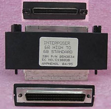
"INTERPOSER 68 HIGH TO 68 STANDARD" IBM P/N 05H3834, Amphenol 04/95.
MidrangeWiki - 05H3834
"05H3834 is an IBM part number for a SCSI interposer which was only needed
for the old tape/disk controller card feature card #6501. It is a passthrough
type connector, with male pins on one side and female pin receptacles on the
other side.
The interposer was needed because the pins on the SCSI cables did not make
proper physical contact with the #6501 card... ... the interposer has longer
male pins than the standard length, as seen on a 61G8324 terminator for
comparison."
Running Wide Devices on Narrow Cables
The Corvette automatically terminates it's end of the SCSI bus with
termination networks on the back side. However, some user intervention
IS required within System Programs.
Uli Link replies:
Not in terms of termination. You must disable "wide messages" if
you connect a wide SCSI device to a wide SCSI controller through narrow
cabling. During negotiation both devices agree both can speak "wide". But the
cabling cannot. So *no* wide negotiation must happen.This is what disabling the
"wide messages" does. If you connect wide SCSI devices through wide cables all
works automagically.
Some combinations of Narrow and Wide
devices on a Corvette
8EFCh "IBM PS/2 SCSI-2 Fast/Wide Adapter/A" or planar section
"Wide SCSI messages - External"
<"Enabled">,
Disabled
Enable for a wide cable and wide external device.
Disabled for a Wide SCSI device attached through a
narrow (8 bits wide) external interface cable.
"Wide SCSI messages - Internal"
<"Enabled">, Disabled
Enable Wide - Internal for a wide cable and at least a
wide terminator (or wide device). Disable for a Wide
SCSI device attached through a narrow (8 bits wide)
internal cable.
Specifications
| SCSI type |
SCSI-2 Fast/Wide |
| SCSI bus path / speed |
16 bit / 20 MB/sec |
| I/O bus path / speed |
32 bit / 40 MB/sec streaming |
| I/O features |
Streaming data transfer
Address parity and data parity |
| RAID levels |
None (use software) |
| Tagged Command Queuing |
Yes |
| Processor |
80C186 at 20 MHz |
| Size |
Type 3 (short) |
| Channels |
Two (one internal/one external) |
| Connectors |
Two internal SCSI-1 or SCSI-2 cabling
50 pin edgecard and 68 pin mini C68
(only one active);one external C68 |
| Devices supported |
7 narrow or 15 wide per adapter
15 on Server 500 on one or two channels |
| Cache std / max |
0 KB / 0 KB (128 byte buffer) |
The Corvette is a SCSI-2, 32-bit MCA 40 MB/s Data Streaming bus master
adapter with dual SCSI-2 16-bit, F/W channels (one 20 MB/s internal, one 20
MB/s external). The dual bus of the adapter prevents access
to internal DASD from the external port and also allows the maximum
cable length to be calculated individually for each bus. Data transfer rates
for 8 bit SCSI up to 10 MB/s, 16 bit devices up to 20 MB/s.
The Corvette supports SCSI Tagged Command Queuing (TCQ), making it possible
to send multiple commands to the fixed disk, and the disk stores the commands
and execute each command in the sequence which will give optimal performance.
Standard 8-bit SCSI devices are supported using either asynchronous,
synchronous, or fast synchronous (10 MBps) SCSI data transfer rates.
SCSI Configuration Flexibility
Systems with the enhanced SCSI device and adapter support allow up to 8 IBM
PS/2 SCSI adapters of any type to be installed in a single system. The maximum
number of SCSI devices which many be configured in these newer systems has also
been increased from 60 to 120. However, other factors, for example, the
type of devices (optical, etc.), cooling requirements, or power consumption of
the devices may limit the number for a particular system.
SCSI Device Order
SCSI device logical ordering and hard drive letter assignment (e.g. C:, D:)
sequence is determined by the SCSI adapter slot numbers, internal or external
SCSI bus connection, and SCSI ID of the connected devices.
Adapters are scanned for SCSI devices beginning with the SCSI adapter in the
lowest numbered slot. Devices connected to the same adapter are logically
ordered according to device SCSI IDs in order from 7 to 0 and then from 15 to 8
according to the priority scheme defined by the SCSI standard. Devices
connected to a SCSI-2 Fast/Wide adapter's internal bus connector are ordered
logically before devices connected to the external bus of the same adapter.
Maximum SCSI Devices Supported
Wide SCSI devices support 16 possible SCSI ID values. The adapter uses one
these values; therefore, the SCSI-2 Fast/Wide adapter can connect up to 15 fast
and wide devices internally or externally in any combination using the
remaining ID values. Narrow SCSI devices support 8 possible SCSI ID values;
therefore, up to 7 narrow SCSI devices can be connected to the internal or
external SCSI buses in any combination using the remaining ID values. Wide and
narrow devices may be mixed on the same internal/external bus by using the
proper combinations of SCSI bus cables, terminators, and/or SCSI connector
convertor adapters.
Note: Use of a 8 bit (Narrow) cable forces the
controller to default to only 7 devices supported on that port, even if all
devices on that cable are Wide.
Fast POST Consequences
Some newer systems also provide a FAST POST option which may be selected
from the system configuration menu or from the IBM logo screen. When this
option is selected, the system will not check for the presence of newly added
SCSI devices unless F1 is also pressed while the IBM logo is displayed. Newly
added SCSI devices will not be configured nor will an error occur if the fast
post option is chosen as the default. To access the system configuration
program, press F1 while the IBM logo screen is displayed to configure the new
SCSI device(s) initially.
Maximum Number of SCSI Adapters
Tim Clarke uttered this after a pint of warm beer:
All **IBM** SCSI CBIOS-flavour (i.e. *not* FD MCS700 OEM) will
share IRQ14 and you only need one BIOS ROM enabled to drive multiple adapters.
So, for example you *should* be able install (in the same slot-type, please)
IBM F+W SCSI-2 "Corvette", IBM SCSI w/cache ("Spock") and IBM SCSI w/o cache
("Tribble") in the same PS/2. No naughties like AHA1640, Storage Dimensions
unless you disable their BIOS ROMs and assign a different IRQ.
OS Limits
Not all Microsoft products support multiple IBM SCSI adapters gracefully.
W9x cannot handle shared IRQs and will drop into MS-DOS compatibility mode. Win
NT handles the shared Interrupts. OS/2, Linux and many UNIX systems support
shared Interrupts.
Server 85 - Sharing External SCSI DASD fails
External SCSI DASD expansion shared between two system fails when one of the
systems is powered down. Systems affected : 9585 0N* MCA SCSI-2 Fast/Wide
controller card.
On the 9585 0N* the trace on the solder
(back) side of the planar running parallel below resistor R351 must be cut. On
the SCSI-2 F/W controller the trace running next to C30 on the component side
of the card must be cut. This trace runs from the fourth pin from the right on
the bottom of the larger IC next to the external connector.
On the Corvettes in my possession, some have no trace at all from the fourth
pin, nor is there a C30 on the PCB. Others have it. YMMV.
RS/6000 SCSI-2 Fast/Wide Boot Support
SCSI-2 Fast/Wide adapters available for the RISC/6000 are recognized as boot
devices on all POWER2 and PowerPC systems. They are not recognized as boot
devices on POWER-based models. Any devices attached to a POWER-based model via
a SCSI-2 Fast/Wide adapter may be used for storage but cannot be used as a boot
device.
SCSI-2 F/W Adapter (4-6, 4-7, 4-C) Boot Support
| Type | Model | Processor | SCSI-2 F/W
Boot Support |
|---|
| 7006 | All | PowerPC 601/604 | Yes |
| 7007 | N40 | PowerPC 601 | No (N/A) |
| 7008 | All | POWER RSC | No |
| 7009 | All | PowerPC 601/604 | Yes |
| 7010 | All "Xstation" | (various) | No (N/A) |
| 7011 | 22x,23x | POWER RSC | No |
| 25x | PowerPC 601 | Yes |
| 7012 | 32x,34x,35x,36x,37x | POWER | No |
| 380,390,39H | POWER2 | Yes |
| 397 | POWER2 Super Chip | Yes |
| G30,G40 | PowerPC 601/604 SMP | Yes |
| 7013 | 52x,53x,54x,55x,560,570,580 | POWER | No |
| 58H,590,591,59H | POWER2 | Yes |
| 595 | POWER2 Super Chip | Yes |
| J30,J40 | PowerPC 601/604 SMP | Yes |
| 7015 | 930,950,97x,98x,R10 | POWER | No |
| 990,R2x | POWER2 | Yes |
| R30,R40 | PowerPC 601/604 SMP | Yes |
| 7030 | All | POWER2 | Yes |
ADF Sections @8EFC.adf 4/10/95
I/O Address
Each adapter must have a unique I/O address
range.
<3540-3547>,
3548-354F, 3550-3557, 3558-355F, 3560-3567, 3568-356F,
3570-3577, 3578-357F, 3578-357F
DMA Arbitration Level
Arbitration level used to transfer
data.
<C>, D,
E, 8, 9, A, B, 1, 3, 5, 6, 7
SCSI Adapter Address (ID)
SCSI ID of adapter. Usually ID7, unless you
have specific requirements.
Adapter IDs available are: <7>,
6, 5, 4, 3, 2, 1, 0
Move Mode Support
Enable or Disable Micro Channel Subsystem
Control Block Move Mode This is the second mode of SCBA
(first is locate mode) which permits the system
processor to move the subsystem control blocks to the
adapters directly.
<Enabled>
or Disabled
Wait State Support
Enable or Disable Bus Master wait states.
If the target expansion card is an older card, it may
not be able to process commands or data from the
busmaster fast enough, and when queried by the
busmaster, it replies with "not ready". By inserting a
wait state, the slower card has more time to signal
"ready". Enabling wait states can slow your busmaster
down.
<Disabled>
or Enabled
Data Parity Exception Handling
This Adapter can generate and detect data
parity on Micro Channel. Data parity must be supported
on both ends of an across-the-bus transmission in order
for this error detection process to be effective. A data
parity enable (-DAPAREN) bus line to the system and
other expansion boards is enabled when data parity is
being used. If the System does not support Data Parity
Exception Handling, this feature will always be
disabled.
<Enabled>
or Disabled
Selected Feedback Return
Exception
Whether a busmaster will report errors
detected in the select-feedback-return process.
When enabled, the busmaster monitors the
selected feedback return and card-selected feedback
buslines. The return line tells the master that it's
target expansion board is responding properly to being
addressed for a read or write operation. If the bus
master does not receive this signal (and SFR has been
enabled) it may mean that the expansion board is not
operating properly or that the signals themselves are
not properly traveling across the expansion bus. This
error causes the master to immediately halt the transfer
in progress and notify the host system of the error
using an interrupt.
Note:
The SFR must be ignored for PC compatibility. If the
System doesn't support the Selected Feedback Return
feature, it will always be ignored.
<Enabled>
or Ignored
100 ns Streaming Data Transfer
Support
This provides better performance. It will
be disabled if the system doesn't support it.
<Enabled>
or Disabled
Target Mode
Target mode should be disabled only if this
system is sharing SCSI devices with another system and
there are more than 15 devices to be shared. Only
15 devices can be configured on each adapter. When target mode is enabled, this
adapter appears as a processor device on the other
system and unless you have specialized software that
can communicate between the two systems through these
processor devices (peer-to-peer communication), there
is no advantage in having target mode enabled. When
target mode is disabled, this adapter does not appear as
a device to the other system, and one more device can be
shared by the two systems. If your system is not
sharing any SCSI devices with another system on this
adapter, it does not matter whether you enable or
disable target mode.
<Enabled>
or Disabled
SCSI Disconnect
Disconnect is a SCSI-bus procedure in which
a device logically stops communicating with the adapter
during certain operations and then reestablishes
communication with the adapter when the operation is
complete. Disconnect should not be confused with
the 'Presence Error Reporting' option for a device in
'Set and view SCSI device configuration.'
If you are using an operating system that
is single-threaded and issues commands to only one
device at a time (such as DOS or
Win95), disabling SCSI disconnect might
result in a slight performance improvement. If
your operating system is multi-threaded (such as OS/2),
disabling SCSI disconnect will degrade the performance
of the SCSI subsystem.
<Enabled> or Disabled
Fast SCSI - External
If Fast SCSI devices are attached externally,
enabling Fast SCSI improves performance
- One external SCSI device enclosure model
3511.
- Up to three external SCSI device enclosures
model 3510.
- Any external configuration where SCSI cable
length isn't > 3 meters.
<Disabled>
or Enabled
Wide SCSI messages - External
'Enabled' if external Wide SCSI device
attached with WIDE (16 bit) cable.
'Disabled' if external Wide SCSI device
attached with NARROW (8 bit) cable -OR-
if an external Narrow
SCSI device is attached with a NARROW (8 bit) cable.
Note:
"Disabled" applies termination to the High Byte on the
adapter itself.
<Enabled>
or Disabled
Wide SCSI messages - Internal
'Enabled' unless a Wide SCSI device is
attached through a narrow (8 bits wide) cable.
Note:
This is almost always using a Wide drive on the 50 pin
edgecard connector.
<Enabled>
or Disabled
Internal/External Bus Mode
'Separate', SCSI devices on external bus
connector can have the same SCSI ID setting as other
SCSI devices connected to internal SCSI bus connector on
the same adapter.
'Combined', all devices must have
unique SCSI ID settings regardless of which SCSI bus
connector is used to attach the devices. Default
is 'Separate' unless you are using an operating system
device driver that does not support independent
operation of the internal and external SCSI buses on
the adapter.
<Separate>
or Combined
Note: SCO Unix and
Banyan Vines can not recognize devices configured on the
SCSI-2 F/W Adapter (DFW as well), when in a 90 /95 level
3 BIOS or higher. This is due to the the internal
and external ports being separated. A special
version of the SCSI-2 F/W Adapter's ADF
(@8EFC.ADF) file is available to allow the buses to be
set to a COMBINED state, which overcomes this problem.
Note: I don't
know what version this is for, nor do I know if later
versions of SCO Unix and Banyan Vines fixed this issue.
The last version of the F/W ADF has "COMBINED" as a
choice.
System Determined
ROM Address Range
Address of 32K block of memory assigned to
adapter. Only one SCSI Adapter will have the ROM
assigned, and any other SCSI Adapter installed will
share that address range.
ESDI Requirements
If the ESDI adapter is also installed, then
the address of the SCSI adapter must be greater than the
ESDI adapter address.
|