|
MPSETUP3.ZIP M-Series PSETUP v3.00C PN30421 (286/386) (zipped image)
M-REFER.ZIP M-Series PSETUP v3.00C PN30421 (zipped files only, 2 extra ADFs, no DOS)
ADFLIST.ZIP M-Series ADF files (zipped files only)
ADFLIST2.ZIP Updated ADF File List (list only; Winword 6 format)
Specifications
PC-386/20 Mainboard
System Firmware
ROM Images
Planar Memory Modules
PC Speaker
CMOS Battery
Expansion Bus Riser
Power Supply
Planar Power Connector
Floppy Drive
Specifications
CPU: i386SX @ 20 MHz soldered in, no upgrade socket
Memory: 2 MB soldered on planar (70 ns chips)
2x proprietary memory connector, 2 or 4 MB per memory card, 70 or 80 ns (?)
Bus: 3x 16-bit MCA slot on a riser
Video: Western Digital WD90C11 Enhanced VGA (on-board), 256 KB video RAM
HDD: on-board DBA-ESDI, ? MB drives
FDD: 3.5" 1.44 MB (34-pin)
I/O: PS/2 keyboard & mouse, 1x 25-pin serial, 1x parallel, 1x Ethernet BNC (PCEN386 only)
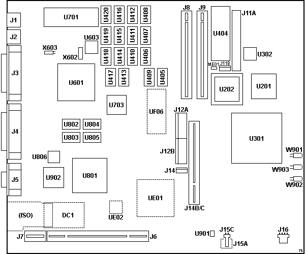
PC-386/20 Mainboard P/N 25382 ISS.4, PCB P/N 33009 ISS.1
![Front [P]](/other/img/photo.gif)
![Back [P]](/other/img/photo.gif)
The reference designators are on the solder side of the PCB.

DC1 Pads for DC converter?
J1 Keyboard port
J2 Mouse port
J3 Parallel port
J4 DB25 serial port
J5 HDD15 video connector
J6,7 MCA riser slot
J8,9 Memory card slot
J11A 40-pin floppy connector
J11B Floppy power connector (Berg)
J12A/B Power supply connector
J14 Hard-drive power connector (Berg)
J14B/C Hard-drive riser slot
J15A Pads for alt. Battery/Speaker connector
J15B Speaker connector
J16 Battery connector
ME01 2-pin jumper (?)
U201 80386SX-20 CPU
U202 Math co-pro socket
U301 RM 24688 SYC0 REV 0 System controller?
U302 40.000 MHz osc (CPU)
|
U404 RM 32846 Am27C1024-150DC ROM
U405-420 81C4256A-70 256Kx4 DRAM (system)
U601 RM 29942 REV 1 I/O controller?
U603 48.000? MHz osc
U701 P8042AH Keyboard controller RM 30426 v.2.0.2
U703 WD37C65CJM Floppy controller
U801 WD90C11-LR Enhanced VGA
U802-805 81C4256A-70 256Kx4 DRAM (video)
U806 90C61-JE VGA clock
U901 LM386 Audio op-amp (PC Speaker)
U902 ADV471KP50E RAMDAC
UE01 Pads for PQFP-160 (Ethernet?)
UE02 Pads for osc (Ethernet?)
UF06 Pads for DIP-32
W901 Network LED (Yellow)
W902 Hard drive LED (Red)
W903 Power LED (+12V) (Green)
X602 14.31818 MHz xtal
X603 32.768 kHz xtal (U602 → U601 RTC)
(ISO) Isolated PCB area (Ethernet front end)
|
System Firmware (POST & BIOS)
Firmware stored in EPROM (27C1024-150, DIP-40).
ROM Images
32846 - RM P/N 32846, PC386 v5.02K, checksum E800
Planar Memory Modules
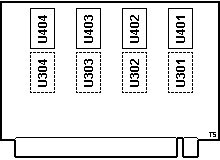
RM PC286/386 2 MB Memory Card
P/N 30388 ISS01, PCB P/N 29042 ISS 1
![Front [P]](/other/img/photo.gif)
![Back [P]](/other/img/photo.gif)

|
U301-304 pads for DRAM
U401-404
MB814400-80,
µPD424400-70, or compatible
1Mx4 DRAM
The reference designators are on the solder side of the PCB.
No components on the solder side.
|
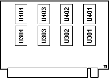
RM PC286/386 4 MB Memory Card
P/N ?, PCB P/N 29042 ISS 1
![Front [P]](/other/img/photo.gif) (source)
(source)

|
U301-304,401-404
MB814400-80,
µPD424400-70, or compatible
1Mx4 DRAM
The reference designators are on the solder side of the PCB.
No components on the solder side.
|
PC Speaker
J15B Speaker Connector
| Pin |
Description |
| 1 |
Speaker Data |
| 2 |
Ground |
Speaker Type
P024R01G-02
8 Ohm
Taiwan
CMOS Battery P/N 26375
![Battery [P]](/other/img/photo.gif)
J16 Battery Connector
| Pin |
Description |
| 1 |
Battery+ |
| 2 |
Key |
| 3 |
N/C? |
| 4 |
Ground |
Battery Type
Lithium ER6K 3.6 V
RM P/N 26375
Still available from various sources under the ER6K name.
Expansion Bus Riser P/N 19710 ISS.1
![Front [P]](/other/img/photo.gif) (source)
(source)
3x 16-bit MCA slot, one with AVE.
The only available machine lacked the riser. It likely uses the same riser
as the older 286 and 386-16 machines but this is currently unconfirmed. Know
more? Please let us know.
Power Supply
RM P/N 28004
Lite-On Type 32188
Input:
220-240 V AC 3.0 A 50 Hz
AC Output:
Monitor only, 2 A max.
DC Output:
+5 V ? A
+12 V ? A
-12 V ? A
Planar Power Connector
Planar Connector Pinout
Similar pinout to the PC AT PSU, but not compatible.

| |
Pin(s) |
Description |
Notes |
| × |
J12A-1 |
N/C; Unknown |
PSU: N/C; Planar: Possibly a locally generated Power Good signal. |
| × |
J12A-2 |
N/C; +5 V DC |
PSU: N/C; Planar: Connected to a common +5 V rail (J12B-4,5,6). |
| |
J12A-3 |
+12 V DC |
|
| |
J12A-4 |
-12 V DC |
PSU: -12 V DC — 7812 reg. ground pin (floating). |
| |
J12A-5 |
Ground for -12 V DC |
PSU: 7812 reg. output pin. Planar: Connected to common ground. |
| |
J12A-6; J12B-1,2 |
Ground |
|
| × |
J12B-3 |
N/C; +12 V DC |
PSU: N/C; Planar: Connected to a common +12 V rail (J12A-3). |
| |
J12B-4,5,6 |
+5 V DC |
|
Warning! If you intent to use a standard AT PSU
as a replacement you must remove the -5 V line otherwise it will get shorted
to the +12 V line on the planar. The power good line should be removed as well,
as the signal seems to be generated by the planar rather than the PSU (or the
pin might be used for a different purpose altogether).
Floppy Drive
Floppy Drive Connector & Cable
40-pin floppy connector with pinout similar to the IBM
40-Pin Card-Edge and
40-pin Planar Diskette
connectors (with +12 V @ pin 40, +5 V @ pin 38, and ground @ pin 36).
The last six pin positions (pins 35-40) are unused by the supplied cable.
The cable and drive-side connector have only 34-pins. The cable is RM P/N 31556
ISS 1.
Floppy Drive Type
YE DATA
YD-701B 8031B
Made in Japan
34-pin data cable
4-pin power connector (Berg)
("industry standard")
|