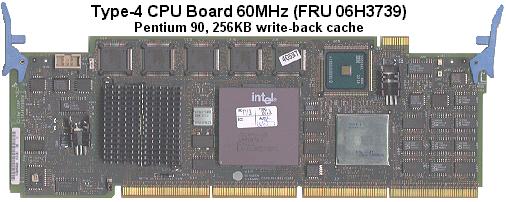
(Photo from Peter Wendt/Dennis Smith's MCA card picture collection)
Content Copyright 2003, Jim Shorney, all rights reserved. Edited by Major Tom.
Why the "Y"?
The Pentium 90 IBM "Y" processor complex for PS/2 Model 90/95 computers
is the most highly sought after PS/2 upgrade because of it's speed and
upgradability. However, some people have experienced unexplained
failures of an otherwise very reliable processor complex after upgrading.
Why? I believe that some of the failures can be attributed to the
power system for the CPU.
The Pentium 90 (actually, Pentium 75 non-MMX and above) CPU is a 3.3
volt CPU. The earlier P60 and P66 CPUs used a single 5 volt power
supply. To provide 3.3 volts for the CPU and the I/O section of the
80497 cache controller, IBM added a second voltage regulator to the circuit
board. While this regulator is adequate for the original 90 MHz CPU,
it is my belief that is needs some rework to handle faster CPUs.
One important factor that many upgraders fail to take into consideration
is the power requirement of the new CPU. This is OK for the typical
socket 5 or 7 clone motherboard, since (for the most part) they are designed
to handle a variety of CPU chips. The Y complex, however, was designed
for only the P90 CPU, with no upgrade envisioned.
Below is a table of the relevant power specifications for several CPU chips
that have been used with the Y. Current specifications are worst-case
values, and are taken from relevant Intel
documentation; Regulator power dissipation was calculated assuming
1.7 volts drop across the CPU regulator.
| CPU Speed |
Supply Current (Amps) |
Regulator Dissipation (Watts) |
| 90 |
2.95 |
5.015 |
| 166 |
4.25 |
7.225 |
| 200 |
4.60 |
7.82 |
| 180 Overdrive |
4.33 |
7.361 |
| 200 Overdrive |
5.00 |
8.50 |
Here we can see that even one of the simplest upgrades to implement,
the 180 Overdrive, draws over 1 Amp more than the stock CPU, and increases
regulator dissipation by over 2 watts! An interposer that provides
a separate power source is one solution that is under investigation by
others. I think my solution is equally viable, and has the advantage
of being cheaper to implement.
The Regulator
The CPU voltage regulator is a three-terminal, low dropout voltage device,
the LT1084CT.
It has a typical current limit of 5.5 Amps, so it should be capable of
handling the upgrade. In fact, this same device is commonly used
on Socket 5 and 7 clone motherboards rated for 200/233 MHz CPUs.
So where's the problem?
The Heatsink
IBM used two different heatsinks for the CPU regulator. One appears
to be a Thermalloy PF430, similar to the Thermalloy PF432G,
the other is similar to an Aavid/Thermalloy 576802.
They are both very similar in size, and are rated for a thermal resistance
of around 25 °C/Watt. I won't go into the thermal calculations
here, but this unit seems entirely too small to dump over 7 watts of heat
into the air. Also, the PF430 has a design flaw which would seem
to make it inadequate for all but the smallest jobs. Look at this
picture (all photos are clickable):
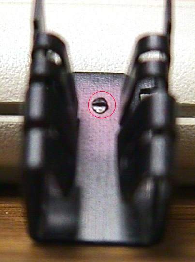
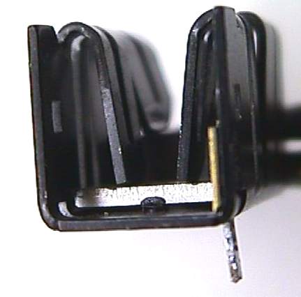
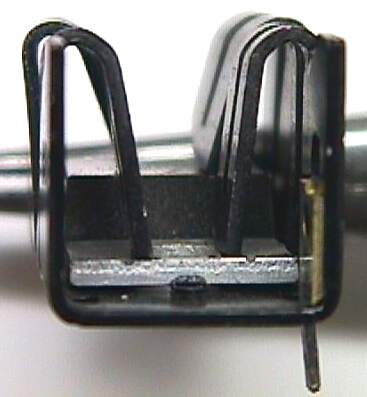
The area of concern is circled in red. The tab of the regulator
IC rests against the horizontal flat. The raised area below creates
an air gap between the regulator tab and the heatsink, which prevents efficient
heat transfer to the heatsink. The next pictures show the air gap:
The Aavid design does not suffer from this flaw, as can be seen in this
photo:
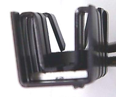
These sinks were removed from two different P90 complexes. Noticeably
absent from both configurations is thermal heatsink compound between the
regulator and the sink; further evidence that this was not meant to handle
a lot of power.
Making it Better
One obvious solution to the problem is to install a better heatsink
on the CPU regulator. I dug through a stack of dead clone motherboards,
and found these heatsinks:
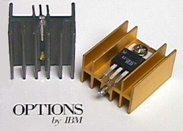
They are both from socket 7 75-200 MHz boards that use the LT1084CT
regulator, so they should be adequate. I chose the gold one because
it has two more fins, and, well, because it's prettier!
Important:
The processor complex is a static-sensitive device! When doing any
work on it, be sure to use standard precautions. Use a grounded soldering
iron, and make sure that you are discharged before touching anything on
the board. It is a good idea to get one of those large anti-stat
bags that clone motherboards come in, and lay the complex on it while working
or any time the board is out of the computer. Your local clone mill
should have lots of these bags laying around. You don't need a big-money
anti static workstation to do this, just a good dose of common sense.
The stock heatsink has one solder tab in the upper left corner that
secures it to the board. Heat this up with a soldering iron
and pull the sink up away from the board. It should slip right off
the regulator once it is loose from the board (another sign of less than
ideal thermal contact...). Pull the mounting pin out of the bottom
of the new heatsink with pliers. Carefully stand the regulator straight
up from the board by straightening out the legs, and bolt the new heatsink
to the regulator tab. Be sure to use a thin coating of heatsink compound
between the regulator and the sink. Make sure the sink does not come
into physical contact with any other components. There should be
enough clearance for everything unless you find a truly monster heatsink,
and it should be mechanically stable enough unless you are planning to
ship the machine somewhere or launch it on the space shuttle. In
this set of photos, the stock P90 CPU is still installed.
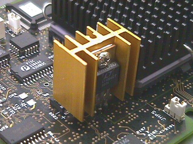
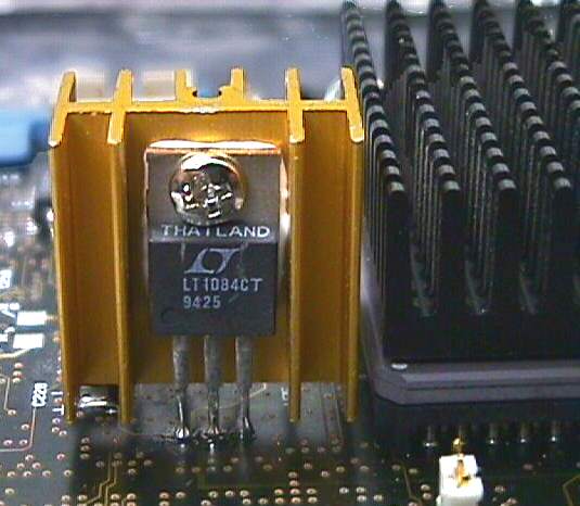
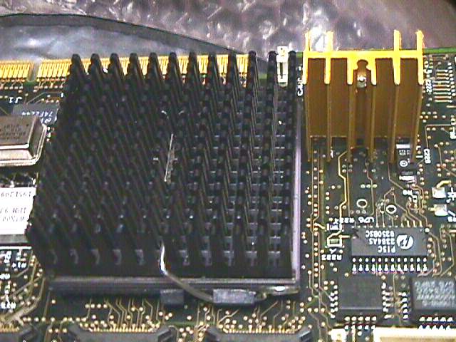
The 'turbo-sink' Y complex with Intel Pentium Overdrive, operating at
60/180 MHz, fitted:
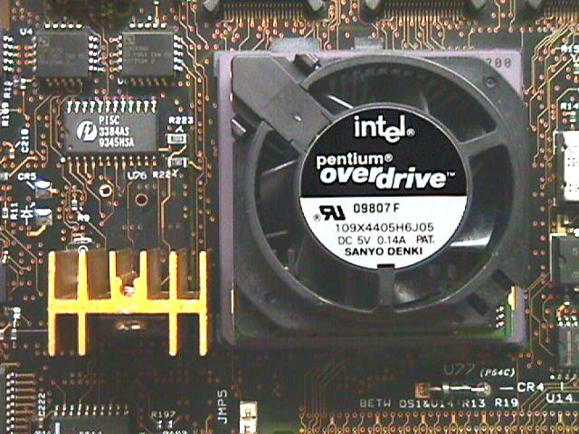
Tim Taylor would be proud!
On this complex, I also replaced the Thermalloy heatsink on the LT1085
regulator with the Aavid unit that was removed from the CPU regulator.
So we're done, right? Well, not quite...
We need more power, Scotty!
What we have now is a CPU drawing more than 7 amps through one connection
point: a plated-through PC board hole that is tied to an inner layer of
the circuit board (the +5 Volt power plane). Call me paranoid, but
I don't like that. I chose to add two jumper wires from nearby +5v
points to the regulator input to spread the current flow out, as shown
in the next set of photos. One wire connects to the anode of diode
CR4 on the top side of the complex, the other to the positive terminal
of capacitor C179 on the bottom. I also made the
fan connection
for the Overdrive CPU to C179 (not shown in this photo).
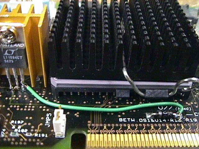
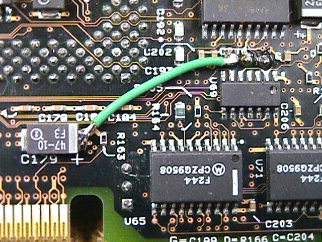
A word about the fan connection: you might think that there is enough
airflow in the 95 case that you don't need the CPU fan on the Pentium Overdrive.
Whether this is true or not, I don't know. But the fan is needed
for another reason besides cooling: the POD has a tach sensor circuit built
into it that reads a tach signal from the fan (the third electrical contact
on the fan). No fan spin = no tach signal, and the CPU downclocks
automatically to protect itself. It still runs reasonably fast, and
can fool you with some benchmarks, but it's not running as fast as it should.
Was all this worth it? I made a simple temperature probe for my
digital multimeter and did some tests. The stock regulator/heatsink
combo hit 55 °C at 100% CPU load, while the new heatsink never got
above 45 °C. I can't vouch for the accuracy of this crude test,
but the results are reasonably close to what I would have expected.
All the images on this page were prepared on the machine that is running
this modified complex.
Why all this fuss about cooling? Click
HERE
for one explanation. Since PC Power and Cooling keeps changing the
location of that link, here's the pertinent text:
Operating Temperature vs System Reliability
At elevated temperatures a silicon device can fail catastrophically,
but even if it doesn't, its electrical characteristics frequently undergo
intermittent or permanent changes.
Manufacturers of processors and other computer components specify a
maximum operating temperature for their products. Most devices are not
certified to function properly beyond 50°C-80°C (122°F-176°F).
However, in a loaded PC with standard cooling, operating temperatures can
easily exceed the limits. The result can be memory errors, hard disk read-write
errors, faulty video, and other problems not commonly recognized as heat
related.
The life of an electronic device is directly related to its operating
temperature. Each 10°C (18°F) temperature rise reduces component
life by 50%*. Conversely, each 10°C (18°F) temperature reduction
increases component life by 100%. Therefore, it is recommended that computer
components be kept as cool as possible (within an acceptable noise level)
for maximum reliability, longevity, and return on investment.
* Based on the Arrhenius equation, which says that time to failure is
a function of e-Ea/kT where Ea = activation energy of the failure
mechanism being accelerated, k = Boltzmann's constant, and T = absolute
temperature.
Getting to 200 MHz
If you dare, the complex can be overclocked to 66 MHz on the bus, to
achieve 200 MHz (or even 233 with an MMX interposer) with Intel CPUs.
Here's one way to socket the oscillator module:

I took an 8-pin DIP socket with machined contact pins and bent pins
1-2, 3-4, 5-6, and 7-8 together in a 'V' shape. It's a perfect fit
to the foil pads on the circuit board! Half-can oscillators that
fit this socket can be purchased from Digi-Key.
9/4/2004 - Some comments on 233 MHz: it's not worth it, in my
opinion. Based on empirical results posted to CSIPH newsgroup,
233 MHz is problematical and more often doesn't work well or at all.
That extra 33 MHz of speed is insignificant, and more trouble than it is
worth to achieve. Here are some comments from Peter Wendt on the
subject:
I don't know the Kingston Upgrade too good, have seen it a couple
of times, but don't have one for testing. So most of my reply is purely
theoretical and based on assumption and experiences I made with different
upgrades.
1. In a different thread in this group I'd shared my impression that
a bus /core ratio above 3 is a bit tricky to handle for the complex card.
Particularly for a 1:3.5 ratio, which *rarely* synchronizes with the 40
MHz DMA and MCA bus controller clock.
In addition the "time window" for synchronization is rather short anyway
and gets even shorter if the bus clock and internal CPU speed differ more
and more. I only have empirical data gained from weeks of experimenting
with the Madex 486007 adapter and a known-good Pentium 233-MMX CPU in an
otherwise stable and well-tested system. The number of crashes and bluescreens
was significantly higher (about 10 times) than with the Pentium Overdrive 200
MMX or with the upgrade adapter running in 3x mode (200 MHz internally).
2. You should take in account that the power drawn by the processor
*may* exceed the onboard 3.3V regulator capabilities - or that of its heatsink.
Less likely however, but we should keep an eye on it. The upgrade is usually
fed from +5 / +12V from the main power supply directly. Usually this is
only the secondary supply for the CPU core - but the rest of the CPU still
runs from off the standard 3.3V regulator. I don't know how the Kingston
gets the core power. If it has no direct connection to the power supply
there might be the reason for frequent crashes: According to the worst
case specs from Intel the 233MMX draws 6.5 Amps on the 2.9V core and 0.75
A on the 3.3V supply. Altogether it sums up to over 21 Watts electric power
- which is far outside the specs for the LT1084 regulator.
3. Cooling is important. Most likely the Kingston kit has a built-on
fan. Does it work ? Is it fed from the main power supply as well ? Or is
the Kingston originally intended for Socket-7 boards ("Overdrive Ready")
only ? The P90 platform is a Socket-5. Not Overdrive Ready and therefore
lacks the two +5V DC fan supply pins. If the CPU fan does not work the
233MMX reacts rather allergic, since it overheats in a few minutes already
- and it has no thermal self-protection, other than the Intel Pentium Overdrive
200 for instance.
4. MMX technology and the 82497 cache controller usually work together
- other than in P60/66 systems with the 82496. I myself run a machine with
the Pentium Overdrive 200 and I did ran one with the Madex and a P-233MMX
- but clocked down to safe 200MHz for an extended time with no problems.
5. The change from 60 to 66MHz does not matter (much) to cache controller
and cache RAMs, even if they are spec'd as -60 parts. The 10% overclocking
(if any) usually causes no problem. None of my machines ever complaint
nor crashed more often than usual. At least not significantly. If you run
Windows you are used to frequent crashes anyway.
Well - I guess that I can't tell you more at that point. As said: I
don't have the Kingston and have no experiences with it.
9/27/2006 - More on the 233 MHz adventure: user reports indicate
that BIOS level 08 seems to have the best chance of working with a 233
MHz CPU/interposer combination. BIOS levels higher than 08 are likely to
hang with a 0129XXXX error.
Check Sandy's
Pentium Interposers and Upgrades
page for more info about interposers.
Thanks to Clinton M. (classic PS/2 driver) for digging this info out of the
dark recesses of the internet.
To date, no AMD CPU attempts have been
successful.
|