|
Table of Contents
[-0-] Version History, Disclaimer & Legal Info
[-1-] Precautions and Warnings before you start
[-2-] Introduction to the Type 4 "Y" Pentium 90 Platform
[-3-] The importance of cooling certain components
[-4-] Modification A) Using a Pentium Overdrive 180 / 200
[-5-] Modification B) Hardwiring the BF0 / BF1 Pins for different Bus / Core ratios
[-6-] Modification C) Changing the Base Clock from 60 to 66 MHz
[-7-] Modification D) Using a Pentium MMX 233 MHz with an Interposer
[-8-] Problems, Workarounds and other stuff
Content by Peter H. Wendt (original HERE). Edited by Major Tom.
Modification C) Changing the Base Clock from 60 to 66 MHz
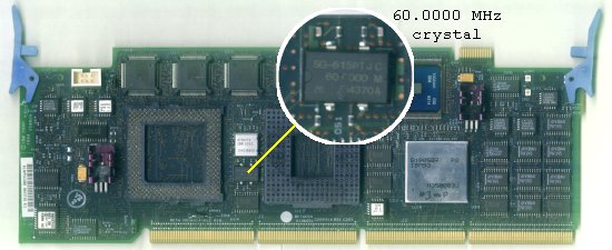
Position of the 60 MHz crystal oscillator
What we have here is not just a simple crystal, it's an integrated
crystal oscillator. A quartz crystal and support circuitry together in one
package. It runs at 5 V and generates a stable (60.0000 MHz) clock signal that
is fed to a clock generator chip (87X0079) and then distributed to the CPU
and other logic.
The oscillator is a 4-pin surface mount part (SMD) and is soldered directly
to the PCB. Pins 2 and 4 are used to supply power (GND and +5 V), pin 3 is the
output, and pin 1 is "output enable" (OE). It uses somewhat unusual package
that is exclusive to the "SG-615" series - the very first SMD oscillators.
You should still be able to get a replacement in the same package.
Search for SG-615 66.0000 MHz (66.6666, 66.6667 should work just fine as well *).
If you can't get oscillator with the same package, you can use the classic
metal can oscillator with trough hole pins or one of the more modern SMD variants,
but you will have to get a bit creative during the soldering to make it fit...
To replace the oscillator you ideally want to use a hot air rework station,
tool designed specifically for work like this. However these are not exactly
cheap and most people won't have them sitting around.
Fortunately it's possible to do the oscillator swap with just a regular
soldering iron and something as simple as a wooden toothpick. Yes - a
toothpick. It can be used as a lever to get the oscillator off the board.
Start at one side and heat up both pins - alternating between them,
while gently trying to lift up that side of the package with the
toothpick. Continue until both leads come up from the board.
If you break the toothpick during the operation, you are pushing way too
hard. Broken toothpick is certainly better than ripped-off solder pads.
So be gentle...
When you are done with one side, repeat the process on the other one, until
the chip is removed.
Now apply some flux and remove the remaining solder from the pads using your
soldering iron and (ideally) some solder wick or solder sucker. Then clean
the entire area with q-tips and isopropyl alcohol. The pads should be clean
and flat before you continue.
Next add some flux and align the new 66 MHz oscillator with the pads - make
sure the orientation is correct - the half-circle mark should be pointing
towards the CPU socket. Tin the tip of your soldering iron and start heating
up one of the pads and the matching oscillator lead at the same time, while
feeding some more solder to it... wait until it starts flowing to both - the
pad and the pin. When you are happy with the connection move to the next pin,
until all 4 of them are done.
Try to work quickly, don't heat up the individual pins for too long, otherwise
you may damage the part - a few seconds should be enough to get the work done.
And that was it. Now you may want to replace the P90 CPU with e.g. a
P100 or 133 while you're at it. The P90 should work just fine with the
66 MHz external and 100 MHz internal clock, it's just a minor overclock,
but if you want to be extra safe and you have a 100 or 133 MHz part at hand,
why not use it...
The platform should come up like normal when you put it back into your
system. QCONFIG from PC-DOS 7 will nontheless claim the machine runs at
60MHz (it does not know better), but the "estimated CPU speed" will be
given as "99 MHz", which is the mathematically correct result from a 66
MHz base clock
and a 1:1.5 (or 2:3) multiplier ratio. Other programs like WinTune will
confirm that it runs at the correct speed.
* I've tried both 66.0000 and 66.6666 MHz oscillator, and there is no major
difference between the two. Those boards that worked with the 66.0000 MHz one
worked with the 66.6666 MHz part too. The performance difference is
negligible (see the test result pages) - and in practice you won't notice any
difference at all.
|