|
Note:
I am not a programmer, electrical engineer, or any
sort of a trained technician. All this info has been
available off the manufacturer's web sites at one
point or the other. There is no disassembled code
here, and I do not deal in Warez.
Warning! If you
are dealing with a medical (life support or patient's
records), factory automation, or business
applications, there is no guarantee that any of the
files or information on this page will be suitable for
your application, installed components, or network
equipment (routers, gateways, etc).
Disclaimer: If you
need mission critical technical support, contact the
hardware (I assume IBM, if not Lenovo) or software
manufacturer.
For those of you willing to accept the
possibility of incompatible drivers, erroneous
references, and out-and-out just wrong information,
please continue. Since this material is presented
as-is, you get what you pay for.
Service Manual (in *.inf format!)
qb3a9y00.pdf N2800e
Thin Client Express Reference Sep 2000
qb3aru01.pdf
Setting Up IBM Network Station Hardware - Type 8364 (Exx,
Txx) Jul 99
QB3ARV01.pdf IBM Network
Station Service Information Type 8364 (Exx, Txx) Sept 99
FW82371EB PCI-TO-ISA/IDE
Xcelerator,(PIIX4E) Preliminary Draft
FW82371EB-Update
PCI-TO-ISA/IDE Xcelerator,(PIIX4E) Specification Update
FW82439TX
System Controller (MTXC) Preliminary Datasheet
PC87309 Super I/O Plug
and Play Compatible Chip
ADM211 0.1 μF, 5
V Powered CMOS RS-232 Drivers/Receivers
Windows 98
on the IBM NetVista 8364 a How-To Guide By
William Walsh
IBM
NetVista 2800 Hacking by Kevin Bowling
..../pc/pccbbs/aptiva
E13Z45US IBM S3 TRIO 86C365 W98SE Drivers
E18Z29UZ IBM S3 TRIO 86C365 NT driver
E11T24A IBM S3 TRIO 86C365 OS/2 driver.
e59z17us.exe S3 video driver for Win 95, 98, and Me 11/17/2004
Note: Because the
Trio3D is an AGP device, OEM Service Release 2.1 or later
for Windows 95 must be installed on your system for the
device drivers to work properly.
..../pc/pccbbs/commercial_desktop
q68t03a.exe S3 Trio video device driver for WinNT 4.0
q68t03a.txt README for S3 Trio video device driver for WinNT 4.0
q63t07a.exe S3 Trio video device driver for Windows 95 v2.41.06
q63t07a.txt S3 Trio video device driver for Windows 95 v2.41.06
q64t04a.exe S3 Trio video device driver for Windows NT 3.51
q64t04a.txt README for S3 Trio video device driver for Windows NT 3.51
q68t03a.exe S3 Trio video device driver for Windows NT 4.0
q68t03a.txt README for S3 Trio video device driver for Windows NT 4.0
q61204a.exe S3 v2 drivers OS/2 6588 6888 v3.03.07 Disk 2 of 2
q61t04a.exe S3 v2 drivers OS/2 6588 6888 v3.03.07 Disk 1 of 2
q61t04a.txt Readme for S3 V2 Drivers OS/2 6588 6888 v3.03.07
Cirrus
Logic Legacy Driver Support:
PRO98M.EXE
Win98 and SE Network Adapter Base Drivers Ver 10.3
PROOS2.EXE
Network Adapter Drivers for OS/2 Ver 10.0
PRO95.EXE
Windows* 95 Driver Release Ver 6.2
PRO2K.EXE Intel
Drivers for Windows* 2000, Final Release Ver 14.0
Caution: Some anti-malware software
detects this file as a threat. This is just a false-positive. To make the
contents invisible to online engines the file was repacked in a
password-protected archive. Use the following password to unpack it:
"falsepositive" (without the quotes)
e100-3.5.17.tar.gz
10/100 Base Driver for Linux* with 2.4.19 to 2.6.x kernels Ver 3.5.17
e100-2.1.15.tar.gz
10/100 Base Driver for Linux* with 2.2.x kernels Ver 2.1.15
VISW98 Search for the file visualswindows98patch.zip and extract VISW98.COM
UNATA APSoft DOS Point Enabler for ATA Cards
The IBM NetVista Thin Client
models N2200 and N2800 ship from manufacturing with
firmware (also called NS Boot version or boot prom).
Depending on the manufacturing date of the thin client you
have, the firmware level may be 07/17/00, 01/12/01,
07/16/01 or 12/06/01. To use the NetVista Thin Client with
Turbolinux 7 on model N2200 and N2800 thin clients, the
firmware level (12/06/01 or later) must be installed on
these clients.
cf-card.H4011201.img.bz2
(01/12/01)
cf-card.H4071700.img.bz2
(07/17/00)
bflash.2800.H4071601.img.bz2
(07/16/00)
bflash.2800.HL072902.img.bz2
(07/29/02)
H2033190 03/31/99
HD25-I
PCI
2.5" Carrier Card Mount a 2.5" HD on a PCI
Card! dead
HD25-I
Setup (Dead)
8364
External Connectors
8364
Planar (-NUS version)
8364
Memory (256MB max)
PCI Riser
8364 Video
HD Power
Connector
HD Power
Connector Pinout
Mounting
IDE HD
Maximum
Drive Size (CF and IDE!)
Configuration for
Hard Drive Boot (from Unal Z)
Mounting
a CF MicroDrive in CF Slot (Cold Steel to the
rescue!)
W98SE
Setup Issues
Preparing
MicroDrive for Use Under W98SE
Thoughts
on the FW82371EB PCI-ISA Xcelerator
Thoughts
on the PC87309 SuperI/O Plug and Play Chip
Clear
Administrator Password and CMOS
Create
Recovery Compactflash Card
Change AC
Voltage
Remove PSU
8364
External Connectors
Note: The Mouse goes
into the connector NEXT to the frame!
Note: Default password
is IBMNCD.
"Foot" 41L4939
Base - 41L4940
Access Setup
Power up the 8364. Then press the F1 key
during the IBM Network Station's logo display, and after
the keyboard LEDs flash.
Note: Pressing F1
during the system's keyboard test causes a false
301 Keyboard Error will display, and you will be prompted
for the administrator password.
Display the OS Diagnostic Messages for OS/2 Systems
To display the OS diagnostic
messages during start up, press Alt+F2 after the white
block and IBM logo appear in the upper left corner of the
screen.
8364 Planar Outline NUS version
CR9 Status (System) LED
J1 USB 1.1 ports
J2,6 Memory DIMM Socket
J3 Three pin header, unk
J5 10/100 Ethernet port
J7 space for X86 Debug Connector
J8 26 pin VIP Connector
J9 Serial 2
J10 Serial 1
J11 Hard File Power (Molex)
J12 Password Override
J13 Boot Block
J14 Compact Flash Connector
J15 Parallel Port
J16 HD Connector (std 40 pin IDE)
J17 Wake on LAN
J18 Power In
J19 Internal Speaker Connector
J20 PCI Rev 2.1 Riser
J21 Aux Audio In
J22 Headphone / Speaker
J23 Video
J24 Microphone
|
J25 Mouse / Keyboard
M1 ZIF Socket 7
M3 Battery Holder, CR2032
U2 5156BM Linear VR (Core Volt)
U3 intel GD82559
U5 PI6C671FV Clock Generator
U6 intel PCIset FW82439TX
U7,11 AD ADM211 RS-232 Driver
U8,9 SGRAM
U10 PC87309IBW Super IO
U12 TAG RAM 32Kx8
U13 L2 Cache 64Kx64
U14 S3 Trio 3D / 86C365
U15 intel PCIset FW82371EB
U19 M29F0408 Flash
U21 ST 7805M 12-5 VRM
U23 Crystal CS4235-KQ
Q1 IRL3103
Y1 25.0000 MHz xtal
Y2 14.318 MHz xtal
Y3 32.768 KHz xtal
Y4 16.934 MHz xtal
|
J11 Hardfile Power connector Molex
43045, mates with a Molex 43025-0400
J16 Hard File
Connector is a standard .1" pitch 40 pin IDE port.
U5 PI6C671FV Pericom
Technology Clock Generator for Pentium Modules Datasheet
U8,9 SGRAM
HYB39S16320TQ-5.5
U10 PC87309IBW Super
IO
U12 IS61LV256-12J
TAG Ram 32k x 8
U13 IS61LV6464-6TQ
L2 Cache 64k x 64
Planar is marked Lite On 20V0. FRU 41L5339 and P/N
41L5342
U3 intel GD82559 -
Intel PRO/100+ Management Adapter.
8364
Memory (256MB max)
Known as 168 pin SDRAM, PC100, 100MHZ Non-Parity (NP).
Unbuffered. CL2
32MB SDRAM DIMM (OPT P/N 01K1136) 01K1146
64MB SDRAM DIMM (OPT P/N 22p0848)
(01K1147) 22P0884
64MB SDRAM DIMM Kingston KTM1136/64
128MB SDRAM DIMM (OPT P/N 22p0851) (01K1148)
22P0885
128MB SDRAM DIMM Kingston KTM1136/128 45L0255 16Mx64 3.3V
8364 PCI Riser P/N 94H1052
8364
Video
This section is focused on the W98 drivers, other
O/S may be different. YMMV. The 8364 uses the S3 Trio3D
86C365 chip with 4MB of video RAM on-planar.
S3 Trio3d stuff, via Internet archive HERE
* Enhanced 128-bit graphics engine
* Integrated 230 MHz RAMDAC and programmable dual-clock
synthesizer
* Enhanced S3® Streams Processor for hardware-assisted
high-quality video playback of two video streams against
a graphics background
* S3 Local Peripheral Bus/Video Interface Port for
direct interface to live video and MPEG-2 peripherals
* 3.3V core logic with 5V tolerant I/O
E13Z45US.EXE
S3 Trio 3D Windows 9x Driver Ver
4.11.01.2206-2.62.22
Tool Kit ver (s3dtkw.dll) 6.00.01
Refresh Rate util ver 2.01.22
Note: Set display
to "STANDARD DISPLAY ADAPTER (VGA)" before applying this
updated driver. The system will have used the default
"PCI VGA Display Adapter" which does not work with the
S3 Trio 3D drivers.
Colors Resolution Refresh
4\8\16\32 640 x 480 60,72,75,85
4\8\16\32 800 x 600 56,60,72,75,85
4\8\16\32 1024 x 768 43,60,70,75,85
8\16 1152 x 864
60,70,75,85
32 1152 x
864 60,70
8\16 1280 x 1024
43,60,75,85
8\16 1600 x 1200
49,60,75,85
Open
8364 Case
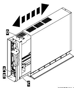
1. Turn off the power supply switch "A".
2. Disconnect all cables from the thin client.
3. Hold the 8364 cover assembly, lift latch "B", and pull
the logic unit "C" out.
Note: If
the logic unit does not want to slide out, you can pull up
on the latch and push in on the white button, forcing the
logic unit out. Or you can hold the 8364 with the logic
unit towards the ground, and then pull up on the latch,
letting gravity help.
4. Carefully lay the logic unit down with the internal
components facing up.
Close the 8364 Case
1. To reassemble the thin client, carefully slide the
logic unit "C" into the cover assembly while depressing
the slide stop "D". Note:
The slide stop will keep the cover from closing...
2. Slide the logic unit completely into the cover
assembly, until the latch "B" is engaged.
To lay the unit flat, remove the foot or pedestal. In
this orientation, the system can support a monitor
weighing up to 90 pounds with the minimum footprint.
The 8364 Network
Station provides a hardware security "lock-down" point at
the back/bottom of the machine. Obtain a suitable locking
cable (usually consisting of woven metal fibers with a
lock on one end). Thread it through the lock-down point
(or hole) and then lock it to a suitable place (such as a
table or other piece of furniture). When this feature is
in use, the system cannot be opened (preventing theft of
internal components) and it cannot be removed from the
table to which it is connected (depending on the length of
the securing cable).
19K1523
IBM NETVISTA 24X CD-ROM SLIM DRIVE
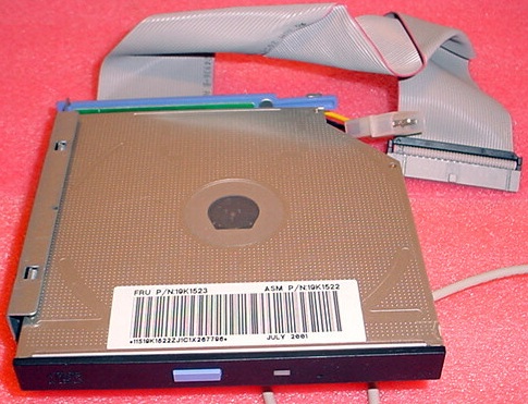
The PCB connecting the ports is a Foxcon 6B-010B-A030.
The drive is a TEAC CD-224E, it pulls 1.5A, +5v.
The good thing is all of the IDE and power connectors are
attached. When the proper terminals arrive, I hope to use
this as a simple CD-ROM drive to install an O/S with.
Power
Connector for IDE Device
Aron Eisenpress chimes up with:
The connector in the 8364 and the 43025-0400
are both 4 pin connectors and they mate. Just looked them
up in the Mouser catalog and they are still available
there too. Note: If
you do order the connector, you have to order the pins
separately!
43025-0400 Molex Micro-Fit 3.0 Connectors
RECEPTACLE 4P DUAL ROW In Digi-Key and Mouser.
Micro-Fit 3.0 Terminal -
Female terminals 20-24 AWG and 26-30AWG
43030-00xx, in tin over phosphor bronze, selective gold
over phosphor bronze
45773, Reel versions of 43030, w/wo lubricant.
46235 Reduced Mating Force (RMF) design, w/wo lubricant.
Micro-Fit 3.0 Terminal -
Male terminals 20-24 AWG and 26-30AWG
43031-00xx, in tin over phosphor bronze, selective gold
over phosphor bronze
Note: These will NOT
mate with the planar connector! This is to help you
understand which terminal that you need!
Salvaging an Existing 43025
Equipped Cable
Folks, there is an extractor tool available
from Molex (HT60923a). Problem is that removing one of
the pins from a 43025 ruins the terminal, and you will
have to cut the terminal off and crimp on another
anyway. Simpler to snip off the mis-wired cable and
crimp new terminals on it, IMHO...
Hard File Connector Pinout vs
24P0621 / 24P0622
8364 Planar Connector
Molex 43045 w/ male pins
Wire colors:
RED | BLK
YLW | BLK
|
24P0621 / 24P0622 Pinout
Molex 43025-0400 w/ female pins
Wire Colors:
BLK | RED
YLW | BLK
|
I finally got a 24P0621 / 24P0622 cable,
and Kevin Bowling had already alerted folks to the swap
of the connectors. Here is how the cable is mis-wired.
Note that in the planar connector, RED and YLW are on
the same side, while on the cable, RED and YLW are on a
diagonal... Best I can determine, the 24P0621 uses AWG
20 wire.
Note: I had trouble
inserting the female terminal into the 43025. Upon
looking at the orientation of the female terminals into
the 43025, I noticed that the female connector resembles
a "U", with the open top towards the clip on the 43025.
By simply turning the female terminal so the "U" was
towards the clip, they clicked into place without
trouble.
Mounting
IDE Drive
Aron says:
The best way I found to mount a laptop hard
drive in these is to screw the drive to one of the
2.5"-to-3.5" mounting rails, then use a wire tie to hold
the rail-and-drive assembly to the crossbar in the
8364. Just make sure the extra tie part doesn't
project above the bar or you could find it difficult to
open up the case again (BTDT).
P.P.S. The service manual is in the EPRM
. It'll tell you most of what you want to
know.
Maximum Drive Size
Martin Etteldorf wrote:
> As the CF slot is just an add-on to the
IDE-Controller, everything up to the max. supported disk
size should work well. I'm running with 2 GB CF at the
moment without any problem, and even the 80 GB disk I
used before was working fine.
I am using a Hitachi 4GB MicroDrive. The full
capacity is reported by the BIOS, and it is selectable
as a Boot device.
Each IDE device can have independent timings. The IDE
interface supports PIO IDE transfers up to 14 Mbytes/sec
and Bus Master IDE transfers up to 33 Mbytes/sec. It
does not consume any ISA DMA resources. The IDE
interface integrates 16x32-bit buffers for optimal
transfers.
P/N 31L5143 CF Card support
Oops, let me clarify - It is a compact
flash card support bracket. It can barely do that. From
the design, it looks as if a CF card prevents the
installed bracket from significant movement. Without a
CF card, the blasted thing wants to push away from the
vertical frame that runs from in front of the PSU, to
the top of the frame by the CPU.
A 2.5" hard drive will not fit in it lengthwise, because
the "well" for the CF card sticks up too far, forcing a
2.5" drive up at the CF socket end so that it will be
about 1/2" above the frame.
Additions to the PIIX4E USB interface beyond UHCI,
revision 1.1 include support for over-current detection
on USB ports 0 and 1. If an over-current condition is
detected on a USB port, that port will be disabled
Netvista
8364 BIOS Settings for Hard Drive Boot (and CF)
Unal Z sent this:
Konfig für HDD-Boot:
Start Options > Startup Sequence > First
Startup Device > Hard Disk 0
Start Options > Automatic Power On Startup
Sequence > Enable
Start Options > Automatic Power On Startup
Sequence > First Startup Device > Hard Disk 0
Start Options > Firmware Selection >
WorkSpace On Demand
Once into the BIOS, look for:
Devices and I/O Ports > Network Setup:
Network Support: Enabled (enables the
built-in NIC)
IDE Devices > IDE Device 0 > enable
High Performance and Read Prefetch. They worked with my
MicroDrive.
Start Options
Power On F1/Esc Options: Enabled (or you
cannot get into BIOS easily)
Network Boot: Disabled (also RPL or
DHCP)
Change NS Boot to WSOD.
This works in the H4011201 (01/12/01) firmware.
Boot. Eventually, you can hit F5 or any key to
continue.
Choose "Service Aids"
Choose "Change Firmware Support"
Choose "BIOS for WorkSpace On Demand"
The system will just dump you out to
the Service Aids screen. F10 and Reboot.
WSOD allows system to boot to all BIOS
based OSs, ex. WSOD, OS/2, and DOS.
Mounting a Microdrive in the CF Slot
From Us, the god Emperor of Microchannel:
I was looking for a simple way to install a
2GB plus drive in the 8364 in a quick manner. Not
wanting to diddle with finding a 43025-0400 and
creating my own cable, then futzing with lashing a
laptop drive to the cross-piece, I settled on using a
MicroDrive.
I bought a Hitachi 4GB CF MicroDrive
(MD4GB-BP), Model HMS360604D5CF00. Now things slowed to
a full stop. The CF slot in an 8364 is for Type I cards.
The MicroDrive is a Type II, which is thicker. It did
not fit. After long meditation, I figured out a way to
get around the width problem. Simply cut the side out.
Armed with a small Swiss Army knife, I
carefully slit the REARWARD side of the CF slot. The
slot is made of thermoplastic, so it's stiff. Once I
slit the slot to the base on both sides, I simply pushed
the detached web towards the rear of the system and it
snapped. It took some wiggling, but the web broke off.
Leave the ends alone, for
they have the retaining slots that keep things tight. A
bit of trimming with a box cutter, and the MD fully
seats.
Further
Thoughts on the FB82371EB PCI-TO-ISA/IDE
Xcelerator,(PIIX4E)
In my struggles to get my Hitachi 4GB
MicroDrive to act as the sole IDE device in the 8364, I
read up on the FW82371EB. It supports Ultra DMA/33, and
so does the Hitachi 3K4. The BIOS may be sensitive to
drives formatted on other controllers, resulting in a
1962 error, no startable drive.
Further
Thoughts on the PC87309IBW Super IO
I don't know if the BIOS supports this, but
the datasheet mentions Serial 2 can support various IR
modes.
Wake
on LAN
You can enable or disable the Network Station’s Wake on
LAN feature by entering the setup utility. For more
information, refer to the BIOS screen summary for “Power
management”
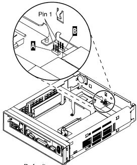
Clear
Administrator Password and CMOS
There are two different
possibilities, WorkSpace On-Demand (WSOD) and Network
Station (NS) Boot. With WSOD, all configuration settings
are cleared from the BIOS. On NS Boot:, only the
administrator password is cleared.
Step #1 Move the
jumpers into configuration -2-
Note: All systems
ship with jumpers installed in configuration
-1-.
Step #2 Power
on the 8364 and wait a few moments. (reconnect power
cable to 8364).
WSOD -
The system LED flashes green at this time
NS Boot - There are no system LED indications at this
time
Step #3 Power off
the system and move the jumpers back into the default
configuration -1-.
Note: If you do not
move the jumpers back, your 8364 may not work
properly.
Create Recovery CompactFash (CF) Card
Note: BOOTBLK: This
creates a copy of the Network Station firmware (flash
image). The flash image that is stored on the CF
card includes both NS Boot and BIOS images. You need a CF
card to complete this procedure (256MB max).
This creates a copy of the 8364 firmware (flash image) on
a CF card.
Note: Once a recovery
CF card is created for an 8364, it can only be used to
re-flash an 8364.
1. Open the Case
2. Insert CF card into connector.
3. Move jumpers into configuration "2".
Note:
All systems ship with jumpers installed in configuration
"1".
4. Power on the 8364. (reconnect the power cable to the
logic unit!)
5. Wait for the system LED to flash green.
Note:
If system LED flashes amber, the image was not created.
Repeat procedure, or see “Resolving hardware problems” on
page 31 for problem determination.
6. Power off the 8364.
7. Remove the CF card and store in a safe place.
8. Move the jumpers back into the default configuration
"1".
Note:
If jumpers are not moved back into configuration "1", your
8364 may not function
Change
AC Voltage
Base (Mounting
Stand) 41L4981
Power Supply (115V-230V) 94H1254
Power Consumption
Normal power consumption for the
8364, while running applications, ranges from 24 to 28
Watts. During periods of inactivity, the system switches
into the suspend state, and power consumption reduces to
approximately 18 Watts. Once the system enters the
soft-off state, power consumption reduces to
approximately 10 Watts.
Note: Power consumption
may fluctuate or vary from these values, depending on
the voltage selection (115V or 230V) of the 8364.
Remove
PSU
Slide chassis out of case. Unscrew the two #2
Phillips below the AC receptacle. Remove the PCI Riser
bracket and the PCI riser. Flip the chassis around and
remove the single phillips through the planar that is
above the AC receptacle. Unplug the planar power connector
just below the IDE and CF connectors by squeezing the
latch and rocking the plug while pulling it out. Now slide
the PSU towards the front of the case. When the AC
receptacle end of the PSU clears the back of the chassis,
push the PSU out of the chassis. Be careful of the power
connector, I rolled the PSU along the length after
removing it about half way so the power connector is
rotated towards the inside. This gave me clearance to
remove the PSU.
PSU Fan
It is a SuperRed CHA6012DS, 12v 0.18A 60mm H x 60
W x 23mm D.
Replacement Fan
Aron Eisenpress said:
Turns out that the fan (SuperRed
CHA6012DS, as per Louis' pages), has sleeve bearings.
The fans seized up, the power supply overheated, and
that was it.
A nice replacement fan with ball bearings is the Delta
AFB0612HH, with the exact same connector. It's 2mm
thicker than the original but that doesn't matter.
Replacement is easy – and it's quieter than the
original too.
Although they have 3
wires, there is no 3rd wire monitoring of the fan's
RPM tachometer speed. It is for a locked rotor alarm
only. Also has over current shut down. Motor winding
impedance will protect fan with locked rotor from
catching fire for up to 96 hours at rated voltage (up
to 13.8v DC)
Size, mm........ 60mm x 60mm x 25mm
Voltage......... 12 volts DC
Current......... 0.25A
Watts........... 3.0
RPM ............ 5000
Flow CFM (Max).. 22.95
Noise (dBA)..... 33.0
|