|
Author: Steve Ciarcia
Source: BYTE Magazine, Aug 1987 page 101+
What would you say if someone asked you to pull the covers off a new IBM
Personal System/2 Model 50, crawl around inside, and report on what it's like
in there? Even I couldn't resist, though I've been known to berate IBM for a
thing or two. I succumbed to curiosity and agreed when BYTE asked me to look at
the PS/2's Micro Channel from the view of an engineer, one who needs to know
more than what's given in the typical glossy descriptions on the new box. I
didn't want a single opinion to dominate the conclusions, so I formed a team
that included members of the Circuit Cellar research staff. Together we
designed our tests, performed them, and came to our conclusions. Our approach
differed from that of usual reviewers; ours was an engineering perspective. We
were more interested in whether the Micro Channel would be useful for
intelligent I/O devices and data acquisition than whether and how fast Lotus
1-2-3 would run.
We evaluated a Model 50 with an 8513 color display using the PS/2 Hardware
Technical Reference Manual to find some of the information and an oscilloscope
to dig out the rest. Unfortunately, the machine we received had no expansion
boards other than the hard disk controller, so we couldn't test some of its
more involved features.
We wrote some assembler routines to check out interrupt-response times and
direct memory address (DMA) loading and compared the 10-MHz Model 50's results
with those of an 8-MHz PC AT. Please accept this for what it is: our first look
at a new machine.
Untouched by Human Hands
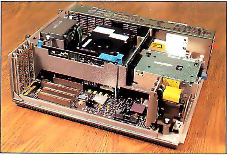
Photo 1. Overall view of the interior of the Model 50 with
its outer case off
The first impression you get when you pull the cover off the Model 50 is
that the insides have been untouched by human hands (see Photo 1).
Everything slides into place, snap-locks without screws, and connects without
wires. (More details of disassembly are covered in "The IBM PS/2 Model 50" in
the July BYTE.)
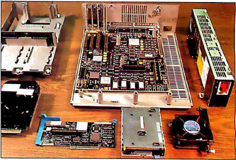
Photo 2. A disassembled view of the Model 50 with its parts
spread out.
In the disassembled system unit (see Photo 2), the motherboard uses
surface mount ICs for everything except the EPROMs, keyboard controller, VLSI
processors, and several gate arrays. You won't be able to fix this one with
standard TTL parts; they just won't fit. Notice the shiny aluminum component
packages produced by IBM. Cloners take note: These won't be easy to crack.
There were a few engineering-change wires on the top of the motherboard.
Given its complexity and the fact that it's at the 01 revision level, that's
not bad at all. It always takes a few passes to get it right.
Distribution of Power
The motherboard has internal power and ground planes to carry the
power-supply voltages. The power connector on the edge of the board devotes 24
of its 50 pins to ground and 17 more to +5 volts. The sticker on the power
supply states that the current is limited to 760 milliamperes per pin for +5
volts, which works out to about 13 amps total.
The PS/2 power supply will work with no load although the regulation is
poor, and, not surprisingly, the "power good" signal might indicate that the
power isn't alright. This is a pleasant change from the original IBM PC power
supply, which could be ruined if it was operated below a minimum load, and an
improvement over the PC AT's power supply, which requires a dummy load on the
unused hard disk power connector.
Each card connector can draw a maximum of 1.6 amps from the +5-volt power
supply. The typical current is limited to 1.4 amps, and a set of formulas in
the technical reference manual describes precisely how to calculate these
values. The logic power supply is regulated to 5 volts, +5 or -4.5 percent, at
the connector, just before the actual pins to the card. You can calculate the
actual voltage on your card based on the connector-pin resistance and the
current through each power pin.
About 25 percent of the card-connector pins are dedicated to power and
ground supplies. No signal is more than 0.1 inch from a ground point (either a
digital ground or a power supply that's bypassed to ground). The card-design
guidelines give specific suggestions to reduce electromagnetic interference
(EMI) from high-speed clock and handshaking signals on each card.
EMI Attack
IBM has given a great deal of attention to reducing EMI in the Model 50.
(EMI is caused by radio-frequency radiation from electrical equipment. The FCC
sets strict standards to limit the intensity of that radiation from computers.)
While its case and internal subchassis are both molded plastic, they're sprayed
with conductive metal to form a continuous EMI shield. The top cover is metal
and has EMI gaskets mating with the case along critical sections. The seal is
so good that only two thumbscrews are needed to hold the two tightly
together.
There is a lock on the case to secure the top cover. Given that the case is
plastic, I'm not convinced that this is particularly secure, but it augments
the thumbscrews. Unlike the PC AT, the Model 50 has no electrical connection to
the lock. It has a keyboard password program, but it's easy enough to defeat:
Just remove the battery and let the CMOS RAM forget.
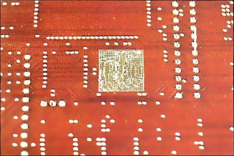
Photo 3. The bottom of the motherboard. The square metallic
grids match up with support posts on the outer case.
Square metallic grids on the bottom of the motherboard (see Photo 3)
match up with support posts molded into the bottom of the case. Embedded in
each post is a small patch of conductive "fuzz" to ensure a solid electrical
connection between the board's ground plane and the case's metallic interior.
In addition, the board's ground plane is segmented to isolate the high-speed
video and high-current I/O devices from the rest of the logic. The I/O
connectors on the back panel are electrically attached to a metal sheet that
makes solid contact with the metallic-coated case. The spring fingers ensure
contact at many points, regardless of manufacturing tolerances.
A side benefit of EMI control is that it will make it easier to ensure that
cards work correctly. A clean power supply, solid signals, and quiet ground
connections go a long way toward eliminating those glitches that occur often
enough to make you tear your hair out, but not often enough to be tracked down
and solved.
The Micro Channel
IBM has ended its practice of supplying schematics of the system hardware,
but it is now giving a much more detailed description of the interface between
the cards and the system. Although this will make it tough for cloners to
duplicate the system, it's a boon for those of us attempting to build cards
that actually work.
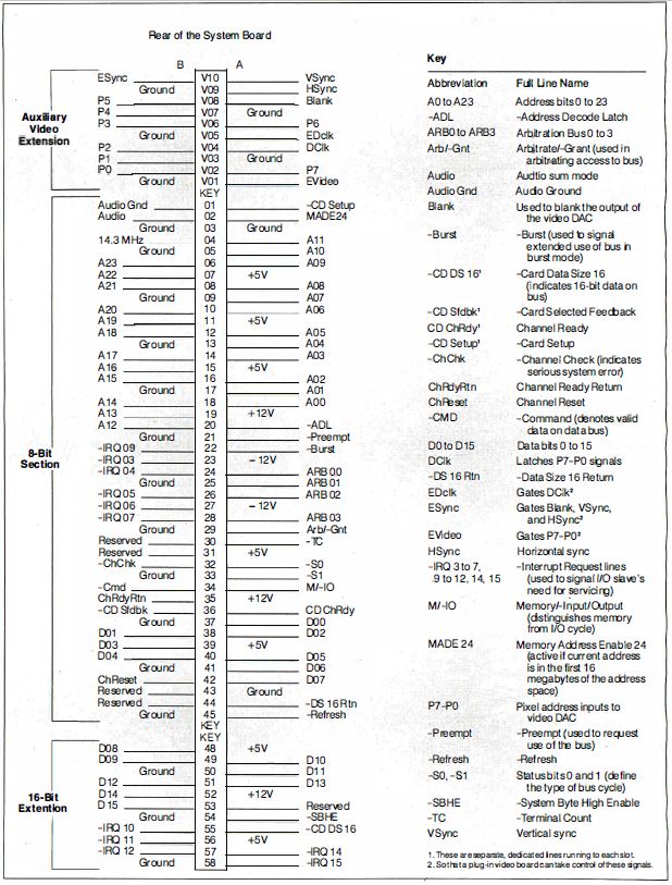
Figure 1: The pin-outs for the various sections of the Micro
Channel.
The Micro Channel isn't compatible with either the PC's or the PC AT's bus,
so none of your old boards will fit the new 68-pin connectors. The connectors
have pins on 50-mil (0.05-inch) centers and are divided into three parts: an
8-bit section that has 24 address lines, 8 data lines, and most of the
controls; a 16-bit extension with 8 more data lines and some additional
interrupts; and a video extension that gives access to the onboard video
hardware. Only one connector has the video extension. Figure 1 shows the
pin-outs for the various sections and gives an idea of the scale involved.
You could omit the 16-bit part of the connector to get an 8-bit version of
the Micro Channel. Perhaps this means that IBM will introduce a low-cost PS/2
system. More likely, however, it's simply a holdover from an original design
based on the 8088 motherboard. The dimension drawings show that even 8-bit
cards need a tab to fit into the 16-bit extension socket; the implication is
that IBM will provide no 8-bit sockets in the PS/2 line.
The Micro Channel has a 32-bit bus extension to accommodate the 80386
processor in the PS/2 Model 80. I couldn't get any information on this, but it
seems a reasonable way to get a wider data path. The 16-bit (and, presumably,
8-bit) cards should work fine in the wider bus.
The video-extension connector allows one card to take over the motherboard's
video circuitry and provide enhanced video output. Those of you who still
aren't satisfied with the new standard 640- by 480-pixel by 16-color output
should take a look at the new IBM 8514/A: its resolution is 1024 by 768 pixels
with 256 colors.
I/O devices now have a full 16-bit address instead of the 10-bit address
used in the PC and PC AT. Each card must decode the full address; partial
decoding that ignores some high-order bits is not allowed. Those 1,024
addresses in the PC and PC AT were pretty much filled up, so having 65,536
addresses to play with in the PS/2 is a definite improvement. Of course, they
will fill up soon enough.
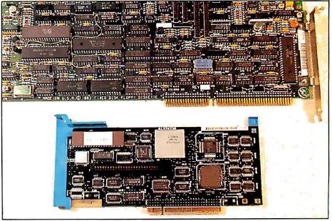
Photo 4. The PC AT's hard and floppy disk controller (top)
versus the Model 50's hard disk controller (bottom).
In addition to the normal digital wiring, the Micro Channel includes an
audio line to a linear power amplifier driving the speaker. This allows any
card to generate an analog sound and add it to whatever's already on that line.
For example, a modem card can now pipe the phoneline audio to the speaker
without suppressing the normal audio beeps and boops from the programs. The
quality is low-fidelity, but entirely adequate. Photo 4 shows the PC
AT's combined hard and floppy disk controller above the new Model 50's hard
disk controller.
If I May Interrupt...
A continuing nuisance in the PC and PC AT buses is the fact that two or more
cards can't share interrupt lines. The lines are active high, and the cards
pull them up with an active driver. If two cards are trying to pull the same
interrupt line in different directions, at least one will lose. This is, in
fact, a good way to burn out a bus driver or two: Short them between the power
supply and the ground.
The PC and PC AT interrupt lines are also edge-triggered, so you get an
interrupt when the line goes from low to high. Unfortunately, it's easy to miss
an interrupt if you have interrupts masked off and you reset the interrupt
controller at the wrong time.
The PS/2 Micro Channel defines the interrupt lines as level-sensitive and
active in the low state. The motherboard includes pull-up resistors for each of
the interrupt lines, so a line that's not connected to anything is in an
inactive state. Several cards can request an interrupt on any line by pulling
it low with an open connector driver (existing cards don't fit in the
connectors, so there's no conflict between old and new cards).
Existing PC AT software might try to reprogram the interrupt-controller ICs
to the rising edge-triggered mode, so external hardware on the motherboard
suppresses those commands. The PS/2 uses the same Intel 8259 Programmable
Interrupt Controller as the PC AT, albeit in a new surface-mount package.
Because the PC AT hardware prevents interrupt sharing, hardware interrupt
handler routines don't have to worry about anyone else using their interrupt.
The PS/2 technical reference manual states that all interrupt handlers for both
hardware and software interrupts on the Model 50 must daisy-chain control along
to the next handler in sequence. Only if the handler has processed the
interrupt can it break the chain.
Each interrupt vector starts out initialized to 0000:0000 hexadecimal, so
the chain of interrupt handlers stops when the last one detects that it's about
to pass control to 0000:0000 (not a valid address for an interrupt handler).
Software interrupt handlers should indicate the error by returning with the
carry-flag set. Hardware interrupt handlers should include a routine that
handles stray interrupts.
For example, suppose we set up several serial cards to share interrupt line
-IRQ4. When one of them receives a character, it pulls -IRQ4 low and activates
the interrupt handler. The handler must check each of the cards to see which
one has the character, process the character, reset the interrupt latch on the
card, and exit. If another card receives a character, it also pulls -IRQ4 low
to indicate that it needs service. Suppose the second card receives the
character after the interrupt handler has checked it. When the handler is done,
it performs a normal end-of-interrupt but is then restarted because the -IRQ4
line is still active. The handler then checks each card again and extracts the
new character from the second card.
But things can get more complicated. Suppose we have a few parallel ports
(the PS/2 supports bidirectional parallel ports) connected to some gadgetry,
with all the cards sharing -IRQ4 with the serial cards. If the serial interrupt
handler finds no serial cards active, it must pass control to the parallel
handler. This way, you can daisy-chain many interrupt handlers together, with
each one aware only of its own existence and that of the next one in the chain.
The same logic applies to software interrupts, which should eliminate a good
deal of the confusion caused by software interrupt handlers "swallowing"
interrupts and disrupting the chain.
Of course, as more devices share a given interrupt line, it takes more time
to figure out which one is presenting the interrupts. For critical applications
(are there ever any noncritical applications?), you might want to have only one
device on an IRQ line. But now you've got the flexibility to choose how to
solve the problem.
Submitting to Arbitration
Although the PC AT bus allows other cards to take control of the bus lines,
it isn't easy to have two bus masters sharing control. The Micro Channel
includes a set of lines that allows several competing devices to share the
address, data, and control lines without conflict. This process is called bus
arbitration.
Under normal circumstances, the processor will use the Micro Channel for
memory and I/O accesses without worrying about other devices. In this case, the
processor supplies the address values and synchronizes the control signals,
while the devices responding to that address may either accept or generate the
data value. The processor is called the bus master because it supplies the
control information. The processor must relinquish control of the bus lines
when a DMA transfer occurs. The DMA controller supplies both the address and
control lines, manages the data transfer, and returns control to the processor
when it's done. During the transfer, the DMA controller is a temporary bus
master.
The PS/2 extends this notion by requiring any device that wants to use the
Micro Channel to submit to arbitration before taking control. Arbitration
starts when any device activates the -Preempt line (see Figure 1) to
request control from the active master. The motherboard includes a circuit
called the Central Arbitration Control Point (CACP), which handles the Micro
Channel's arbitration functions. When -Preempt becomes active, the CACP sets
the Arb/-Gnt line to Arb to begin a new arbitration cycle.
Each device that wants control of the Micro Channel puts its 4-bit
arbitration level (essentially a priority) onto the ARB0 through ARB3 lines.
The details are a little tricky, but basically all the devices drive the lines
at once and check for mismatches between their data and the resulting value of
the common ARB lines. The winning device continues to drive the lines, while
the losing devices disable their drivers. As a result, everyone knows who won
immediately. The CACP then drives Arb/-Gnt to -Gnt to allow the winner to take
control of the Micro Channel.
Devices that transfer data in bursts, like hard disk drives and so forth,
can assert the -Burst line to indicate that they will be using the Micro
Channel for awhile. However, -Preempt overrides -Burst, and the CACP will
terminate the bursting device by starting a new Arb/-Gnt cycle. If the bursting
device doesn't relinquish control within 7.8 microseconds (us) of a -Preempt,
the Micro Channel times out and causes an error.
The nonmaskable interrupt (NMI) is assigned an arbitration level higher than
any programmable device on the Micro Channel. This ensures that a critical
error will be recognized, no matter what else is going on. Unfortunately, RAM
-Refresh is still handled on the Micro Channel and is assigned a priority even
higher than the NMI. Thus, DMA transfers will "burp" every 15 us or so when
-Refresh occurs. The technical reference manual notes that about 7 percent of
the Micro Channel's bandwidth is dedicated to -Refresh. I'd be happy to pay
more for a RAM controller to get -Refresh off the Micro Channel in exchange for
smooth DMA transfers. Maybe next time... in the PS/3.
POS and POST
The PS/2 includes a new feature called Programmable Option Select (POS),
which allows you to set up all configuration information with software rather
than with DIP switches or jumpers. In fact, the technical reference manual
specifically prohibits DIP switches and jumpers on cards. The Power-On Self
Test (POST) software initializes the cards when the power is turned on, so
you're assured of the right setup every time. You can also display which cards
are installed in which connectors, which ports they're configured to use, which
interrupts are active, and so forth, right on the screen without removing the
machine' s cover. Even better, you can change the configuration from the
keyboard without having to figure out which switch is which.
The line called -CD Setup (Card Setup) forces the card to a mode where it
responds to I/O operations at addresses 100 to 107 hexadecimal, regardless of
its normal addressing. There is a separate -CD Setup line for each Micro
Channel connector, another for the video hardware, and another for the rest of
the motherboard hardware. As you might expect, only one of the -CD Setup lines
can be active at a time, because all the hardware responds to I/O at the same
addresses during setup.
The POST code first determines what hardware is installed and then verifies
that it matches the configuration information stored in CMOS RAM. If everything
matches, the cards are initialized by writing configuration data into their
registers. If you decide to change the cards, the POST code tells you to run
the System Configuration program to create a new configuration file. You can't
use the PS/2 until all the hardware is correctly initialized.
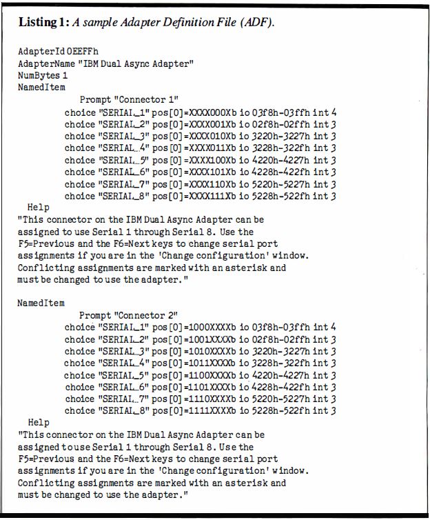
Listing 1.: A sample Adapter Definition File (ADF).
Both the POST code and the System Configuration program read a pair of
identification (ID) bytes from each card. The hexadecimal representation of
these bytes specifies an Adapter Definition File (ADF) on disk that defines all
the possible setup variations for that card. For example, the ID bytes for the
IBM Dual Async Adapter card are EE and FF hexadecimal, so the ADF filename is
@EEFF.ADF. Listing 1 shows the contents of that file. Note that serial
ports 2 through 8 share -IRQ3.
Because the system we received didn't have any additional cards installed,
we couldn't fiddle around with the System Configuration program as much as I
wanted to, but the principle is excellent. For the first time, it's possible to
give online help to a user trying to resolve conflicts between various cards in
the system, and that's a step in the right direction.
One possible snag: IBM is assigning unique IDs only for its own cards. The
rest of us are on our own, so you can rest assured that two companies will
introduce two different cards with the same ID. How this will be resolved is up
in the air, but I'm sure one of the two will have to install a jumper block to
select the card ID. That's the way it goes.
Note: There was an issue with the early POSID
automated phone system, callers thought they could give their firm’s info and
card info, then hung up. In reality, the phone system had to go to another
option and no call was returned...
I'm quite sure that the automatic configuration works, because I used it
after taking the system completely apart. The configuration data is stored in a
battery backed CMOS RAM on the motherboard. The battery is located on the
subchassis just over the speaker. After about 15 minutes, the data in the CMOS
RAM evaporates. Of course, I didn't think of that when the PS/2 didn't power up
correctly. I could only imagine how annoyed BYTE was going to be when I
returned a dead loaner.
Having nothing to lose, I booted up the Reference Disk. A utility
automatically deciphered the error numbers into plain English: The CMOS date
and time were invalid, and the battery was dead. It reminded me that this will
happen whenever the battery is dead or freshly installed. I reset the date and
time and then let the utility automatically identify the hardware. It reloaded
the CMOS RAM and rebooted the PS/2. Elapsed time: under 5 minutes. Whew!
Opening Night Performance
It's difficult to decide what to test on a machine that's so new you don't
even have cards that fit the sockets. I decided to run some timing exercises to
measure how well the PS/2 could handle interrupts. I make no pretensions that
these are comprehensive tests; the code is certainly not optimized.
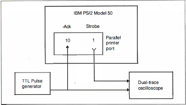
Figure 2. Our interrupt test hardware. We replaced the
standard interrupt handler for the PS/2's parallel printer port with a
specialized one. We measured the interrupt time delays by connecting a
dual-trace oscilloscope to both the Ack line and an output-port bit controlled
by the interrupt handler.
The parallel printer ports on the PC AT and PS/2 can generate a hardware
interrupt from a pulse on the Ack line. We replaced the standard interrupt
handler with a specialized one for these tests. An oscilloscope connected to
the Ack line and an output-port bit controlled by the interrupt handler allowed
us to measure the time delays (see Figure 2).
Because the test programs were written on the PC AT, I got some first-hand
experience with the IBM PS/2 Data Migration Facility. The DMF is an adapter
that connects a PC AT (or PC) printer cable to the PS/2's printer port. The
COPY35 program (on a 5 1/4-inch disk) sends files from the PC AT's disk to
RECV35 (on 3 1/2-inch disk), which receives the file and stores it on the
PS/2's disk. Sounds simple enough.
There was, of course, a slight complication. The PS/2's POST decided that
when the parallel printer port had the DMF adapter installed, it wasn't a
printer port, so it omitted the port address from the BIOS data area. Our test
programs read the port address from that area, as all good programs should,
rather than hardcoding the addresses as constants. After a little team
discussion, we wrote a tiny Debug script to force the right address back into
RAM. Mutter. Grumble.
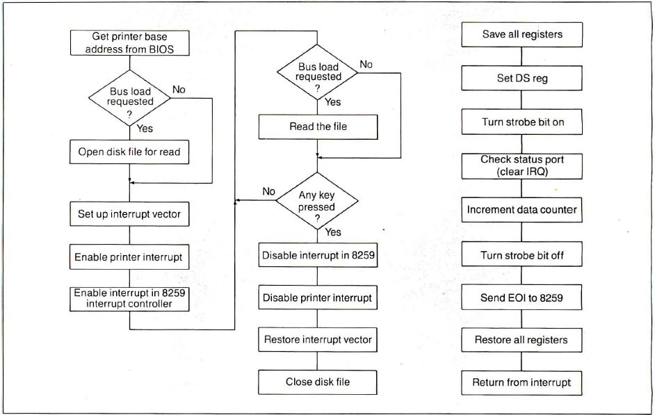
Figure 3. The interrupt test program: 3a shows a general
outline of the main program's operations; 3b contains the functions performed
by the program's interrupt-handler section, detailed in listing 2.
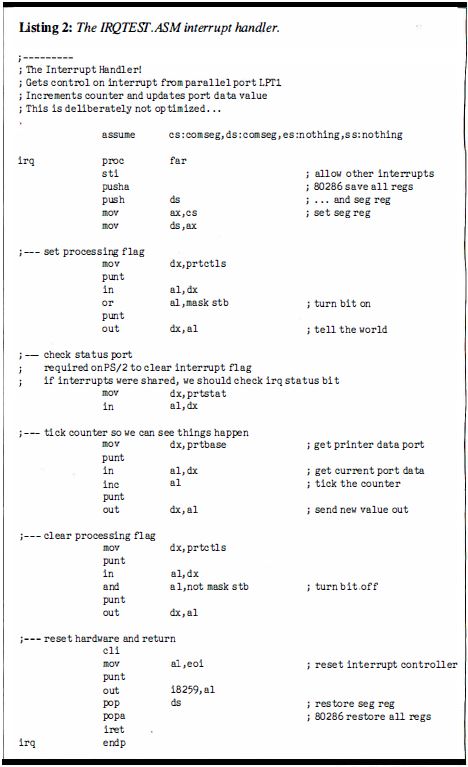
Listing 2. The IRQTEST.ASM interrupt handler.
Figure 3 shows the general outline of the test program, and
Listing 2 shows the interrupt-handler section. The program assumes that
it's running on an 80286, but it will run unchanged on either a PC AT or a PS/2
system. We needed some interesting tricks to use the new level-sensitive
interrupt hardware. For example, the interrupt handler reads the printer-status
port. If several cards are sharing the hardware-interrupt line, there is a test
to make sure that the printer port caused the interrupt. If you don't read the
status port, the hardware won't reset the interrupt-pending bit, and the PS/2
will hang in a tight loop, responding to a stuck interrupt. It's easy to spot
on the scope, but the technical reference manual makes no mention of that
requirement.
Time Trials
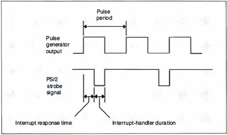
Figure 4. The interrupt timings. The delay equates to the
interrupt-response time, or the length of time between presenting the interrupt
and the response of the interrupt handler.
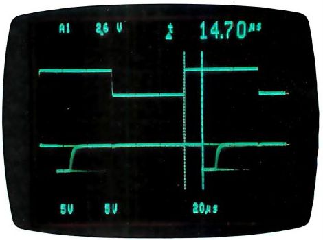
Photo 5. An oscilloscope shot of a simple interrupt response
on the Model 50.
First, we measured interrupt-response time (see Figure 4) with a
minimal system load. The PS/2's timings (see Photo 5) registered a
minimum of a 15-us delay from the rising edge of the Ack line to the first
interrupt-response output. The PC AT weighed in at about 20 us (see Photo
6). The 10-MHz Model 50 runs about 25 percent faster than an 8-MHz
AT-simply the ratio of the clock frequencies.
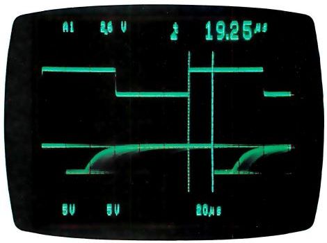
Photo 6. An oscilloscope shot of a simple interrupt response
on the PC AT.
The PS/2's printer port produces much cleaner pulses than the PC AT's.
Although the specifications say that both ports use the same pull-up resistor,
it must be that the PS/2 has an active pullup, the monochrome card on our test
PC AT had some problems, or the difference is the result of the PS/2's better
shielding and busing.
If the processors are busy with a non-interruptible task when the interrupt
is presented, you get a variation in response times. For example, the
hardware-timer interrupt occurs 18.2 times per second and can't be interrupted
by the lower-priority printer interrupt. The DOS call I used to check for a key
press might also disable interrupts occasionally.
The longest delay on the PS/2 was about 60 us, compared to the PC AT's 80
us. Again, these are roughly proportional to the clock ratio, so I wasn't
surprised. Some of the interrupts are lengthened because a timer interrupt
occurs while they are active. There was no easy way to measure the increased
time, but it seemed to be roughly 10 to 20 us.
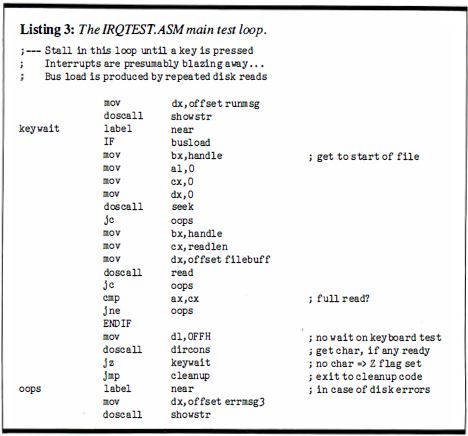
Listing 3. The IRQTEST.ASM main test loop.
I wanted to measure the effect of the new Micro Channel arbitration on the
interrupt- response time, so we added a DOS call to read a disk file while the
interrupts were active. Listing 3 shows the main loop. When the bus load
is not zero, the DOS calls are assembled. Each read pulls in 10,000 bytes of
data from the file. For the sake of simplicity, we used COMMAND.COM as the test
file. The latency remains about 60 us, but the longest delay grew to over 300
us. You can stretch the interrupt to more than 200 us with Micro Channel
operations that have a higher priority.
What's going on is that the printer-port interrupt is now contending with
the disk controller data transfers. It appears that the controller is using a
DMA transfer with a higher priority than the printer port interrupt. The delays
and stretched interrupts are due to that arbitration.
For comparison, if you run the same program on the PC AT, there is
absolutely no interference from the disk. A quick check of the PC AT BIOS
listing will tell you that the PC AT doesn't use DMA for the hard disk; it uses
a program loop to transfer sectors from the controller card to RAM. And those
transfer loops are interruptible by the printer port. Surprised?
More Value Than Aggravation
IBM is preparing for a multitasking operating system (the long-awaited
OS/2), so many of the decisions in the BIOS are made on that basis. Using DMA
to transfer the data lets the new hardware arbitrate on a cycle-by-cycle basis
between contending Micro Channel users. It's your job to match the hardware and
BIOS functions to the task at hand. Make sure that you measure the system under
real-life conditions to avoid surprises.
If all you're doing is running spreadsheets, there are cheaper ways to get
25 percent more speed than buying a PS/2 machine. But if you're building
systems that get down to the bare metal, the Micro Channel will make your life
a lot easier. One complication is that the BIOS listings aren't around to bail
you out of tight spots. You have to depend on the published interfaces. Time
will tell if all the critical details show up in the manuals.
Only IBM could introduce a new PC system with an incompatible bus, different
video adapters and displays, yet another keyboard interface, and a pair of
incompatible floppy disk formats and still call it PC-compatible. Anyone else
trying to pull this off would suffer The Death of 10,000 Paper Cuts in the
published reviews. But the IBM people define what they mean by PC-compatible,
so they can get away with it as long as the product supplies more value than
aggravation. The PCjr, Portable PC, and PC Convertible didn't, but the PS/2
does. IBM doesn't have to apologize for this one.
I'm most impressed with the level of care and attention that's gone into
defining and specifying the requirements for new Micro Channel cards and
programs. The Micro Channel allows simple, automated device setup, has the
potential to support intelligent I/O subsystems, and has room for growth. The
PS/2 looks good, and I'm looking forward to some interesting projects with
it.
Special thanks to Ed Nisley for his collaboration on this article.
Steve Ciarcia (pronounced "see-ARE-see-ah") is an electronics engineer
and computer consultant with experience in process control, digital design,
nuclear instrumentation, and product development. The author of several books
on electronics, he can be reached at P.O. Box 582, Glastonbury, CT
06033.
|