|
Locate Type-Model
Open the Case
How to fix a "Broken" Door
Plasma Display
Information
VGA,
CGA and EGA resolutions
Color
graphics contrast
Text
mode contrast
Auto-dim
feature
External
PS/2 displays
Color to
Gray Mapping
Turned-on
Display
Plasma
Display Brightness
Close
Plasma Display
What is the Plasma
Display?
Why does Plasma
Display Get So Hot?
"Cool"
Windows Color Schemes
Plasma PCB
Remove Hard Drive
Miniture Right Angle KB
Plug Identity
Minature KB Connector
Pinout
External Storage Device Port
External
Storage Device Cable
ESD
Cable Pinout
ESD Cable Hosiden
Connector Pinout
Cable Source
Remove power On Password
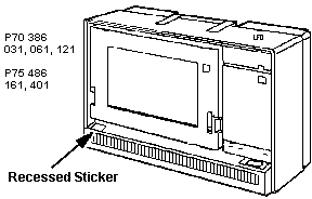
Locate
the Type-Model
Opening
the Case
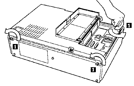
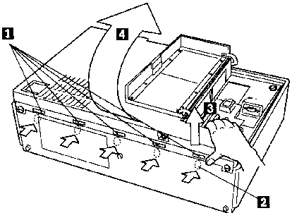
1. Strongly push
below latch to release.
2. Work right to
left. Lift edge of rear cover outward to clear
catch.
3. After releasing
all the five latches, lift and remove the rear
cover.
Note: There are two
additional catches, one to each side of the carrying
handle.When you lift up the rear cover, it pivots on
them.
How to Fix
a "Broken" Door
From Us, the god-Emperor of Microchannel
How many times have you seen the ports cover hanging loose
off of a P70 or P75? Chances are, it ain't broke, just
discomboobulated.
Open the case. (unscrew the three captive screws, pry
out and up on the bottom edge). Pull up on the bottom
edge and rotate it up on the pivots at the top rear of
the case.
Look at the slots where the ports door hinges enter the
case body. See the wide end? If you look on the interior
of the case on the opposite of the wide ends, you will
notice a pivot point for the metal hinge to fit into.
Remove the ports cover by pressing the hinge inwards
(relative to the port cover).
Look at the "U" shaped arms of the hinge. Are they
straight out from the metal strip? They should be at
right angles to the metal strip. If they aren't,
_carefully_ bend them so they are.
Now reinsert the hinges through their slots and pop the
hinge points back into the matching pivots. You may have
to carefully press the hinges inwards, since the pivots
have a lip around them. Shut door.
If the hinges want to pop free, carefully bend them
outwards just a little more, so more force is exerted
against the pivots,
Plasma
Display
Information
The computer has a gas plasma display that
shows program colors in up to 16-level monochrome shades
with a VGA of 640 X 480 resolution. Some programs may not
be designed to take full advantage of the plasma display,
or could benefit from minor changes. Here are some tips
for best results.
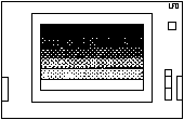
CGA and EGA resolutions-Programs
using CGA and EGA resolutions are supported by this
display; however, program screens will not use the
entire plasma display area, and graphics shapes could be
slightly distorted. How much area of the plasma display
is used by VGA, CGA, and EGA is illustrated in the
figure below. For best results, use the version of a
program that supports VGA resolution.

Color graphics contrast-The
plasma display automatically converts program colors
into different monochrome shades. Some programs start
with colors that lose contrast when converted. You can
usually change colors from within the program to help
increase the contrast.
A program will not start;
parts of a program screen are missing-Some
graphics programs, for example, Microsoft Windows i386
versions 2.1 and below, may not recognize the graphics
capabilities of the plasma display and other PS/2
monochrome displays. This could appear as start-up
difficulty, or faded/missing information. To correct
this situation, put the plasma display (or the attached
PS/2 monochrome display) in graphics mode before
starting the program. To do this, type MODE CO80 at the
DOS prompt, then press Enter.
Text mode contrast-The
contrast in text (non-graphics) programs is best when
the plasma display is in two-shade text mode. The
display is in this mode when the computer is turned on,
but could be put into graphics mode by a program. To
return the display to text mode, type MODE MONO at the
DOS prompt, then press Enter.
Auto-dim
feature-The plasma display is
automatically turned off to extend its life if no data
is received from the system or entered from the keyboard
or an auxiliary device for 10 minutes (default value).
The default value can be changed by using the backup
copy of the Reference Diskette. To change the default
value, go to the Auto-Dim Time. The following shows the
path to the Auto-Dim Time.
Main Menu>Set
Configuration>Change Configuration>Auto-Dim Time
There are two ways to turn on the display again:
1. Pressing SHIFT
2. Moving the mouse.
If the mouse picks up vibration from a desk which turns
on the display again, change the Auto-Dim Reset from
Keyboard and Aux. Device to Keyboard Only. The following
shows the path to the Auto-Dim Reset.
Main Menu>Set
Configuration>Change Configuration>Auto-Dim
Reset
External PS/2 displays-The
computer supports all PS/2 displays with VGA resolution.
If you use the same program with the plasma display or
an external PS/2 display, the best choice for program
colors could change depending on the display you are
using.
Color
to Gray Mapping-There are some
applications that are developed for color displays but
can be used on monochrome displays. When using such
applications, reset the Color to Gray Mapping to Green
Signal Only. Setting RGB Mixed Signals (default value)
may result in an unpredictable display image. The
following shows the path to the Color to Gray Mapping.
Main Menu>Set
Configuration>Change Config>Color to Grey
Remapping
Turned-on Display-The
default value, Primary, turns on only one display that
is considered by the system to be the primary display.
When no external PS/2 display is connected to the system
unit, the plasma display is considered the primary
display and only VGA mode is supported. But when an
external PS/2
display is connected, it is considered the primary
display and VGA or XGA mode is supported for the
external PS/2 display. The value, Plasma and External,
turns on both the plasma display and an external PS/2
display. Only VGA mode is supported. The following shows
the path to the Turned-on Display.
Main Menu>Set
Configuration>Change Config>Turned-on Display
Plasma Display Brightness
You can reverse the brightness of standard
text and emphasized text in DOS through a simple command,
BRT. This command lets you set standard text brighter than
emphasized text, or vice versa. The Reference Diskette
contains this command program and a program to install it.
When you attach an external PS/2 display or use certain
programs, the brightness is not selectable. That is,
emphasized text is always displayed with brighter
characters.
How to Install the Brightness
Program
To change the brightness levels, you must first
install the brightness program from the Reference
Diskette onto the fixed disk drive or bootable DOS
diskette.
1 Start computer using the operating system.
2 insert the Reference Diskette .
3 Type A:BRIGHT and press Enter.
4 Follow the instructions on the screen.
After Installing the brightness program, use the
following instructions on how to change the brightness
level.
To Change the Brightness Level
Go to the DOS prompt (usually "A> " or "C> "),
then:
Standard text brighter than emphasized
text, <BRT /H - Enter>
Emphasized text brighter than standard
text, <BRT - Enter>.
Note: The brightness
program is used only in the default monochrome text mode
of the plasma display. It is not used with graphic
modes, color modes, or an external PS/2 display.
Close Plasma Display
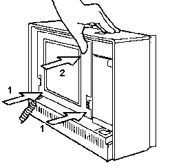
First push back the lower edges into the case. Now push
the upper edges back into the case. Seems odd, but it
works.
What is the
Plasma Display?
Peter Wendt writes:
Technically it is a sort of "cold cathode tube". It does
not use a heater like radiotubes and the "cell" is filled
with a neon-argon gas mixture. There is a negative cathode
and a positive anode to which a "high voltage" (about
170V) is applied. The cathode is then covered with an
electroluminence glow emitted by the excited electrons
within the gas compound. The anode is a thin,
semi-transparent metal coated sheet of low-temperature
glass. We look through the anode into the grid of
individual local gas cells. These orange "Plasma screens"
are closer to the neon lamps that can be found in
nightlights than to real tubes. They are grids of very
tiny neon lamp cells on a common carrier and covering
glass.
Another cousin within that technology is the "Nixie"
display tube, where the multiple cathodes are formed like
numbers, letters and signs. Or the Beckman / Sperry "flat
panel displays" (early multi-segment displays) of the
70's. Modern plasma screens (as used in flatscreen TVs)
are basically the same technology, but there is an
additional layer with RGB triplets that light up when the
underlying neon cell is activated. Brightness control is
very tricky and mostly achieved by pulse-width modulating
the corresponding cell. A cell can only be on or off,
altering the applied voltage results in only marginal
brightness change (below 10%). Therefore "new" plasma
screens are an interesting mix of very old and very new
technology. The basic technique goes back to the Geissler
tubes of the 19th century, over the neon lamps of the late
19th and early 20th century and needs todays complex and
fast computer / microcontroller support to work at all -
generating the appropriate column / row / intensity
control signals.
Their advantage over TFT LCD is the far lower count
of active elements - resulting in an immanently higher
reliability and lower production losses as well as the
absence of a "backlight". They are self-illuminating
screens.
Why does the screen on the P7x get
so hot?
Peter Wrote:
Well - this is a symptom of its function.
The orange screen is commonly called 'Plasma Display' (a
hot word ;-) ) but the correct technical term is 'Gas
Discharge Display'. The principle of function is in
brief that you have a cell with a luminous gas between
two electrodes for each dot (or pixel). The one
electrode is Ground, to the other is a voltage applied
between 70 and 100VDC. The gas in the cell is caused by
this voltage to emit light. You know these lights on the
front of your oven in the kitchen? same principle but
much smaller and many of them combined in a large
circuit.
The controller circuits are soldered
directly to the back of the screen. Both - the
gas-discharge element and the controller circuits give
up some heat which is neither dangerous nor unnormal.
That's all. These screens are a high-voltage technology
unlike to LCD-screens (these black on whites as used in
most modern laptops) - these LCDs are low-voltage /
indirect lighting technologies - however the lamp to
backlight them is a high-voltage again. The
plasma-display is a high voltage / direct lighting
screen, which needs no backlight.
The main disadvantage: some higher
power-consumption, normally not possible to feed it from
batteries, somewhat complicated shading / contrast
control. Main advantage: rigid, temperature independent
(while self-heating :-) ), not very much pressure
sensitive. Makes a good hand-warmer in cold times .... !
"COOL" Windows Desktops
WfW 3.1x - Control Panel>Color>Color
Schemes, use "Plasma Power Saver". W95 - Display, set
the desktop to black. Your display will stay slightly
warm, but the display will be mostly black.
Plasma
Control PCB M480L640HB53 (single row
connector plasma screen)
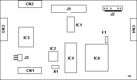
CN1 Bottom
grid controllers
CN2 Top grid
controllers
CN3 Right
grid controllers
CN4 Left
grid controllers
F1 SOC 125mA
IC1 TI
SN755787
IC2 MN5130 |
IC3 TI
SN755783A
IC4 TI
TMF1059N
IC6 API348A
J1 Signal
cable from plasma controller
J2 Power
J3
Brightness slider switch
X1 800NDK04
xtal |
This PCB was mounted to a Matsushita Electric plasma
display MD480L640PG4, P/N 64F8801
Hard
Drive Removal
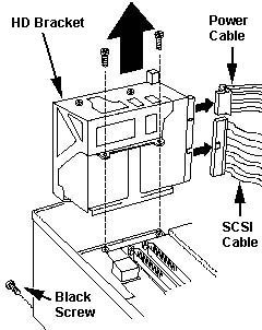
Detach power cable from system board.
Detach SCSI cable from system board.
Remove both screws from the HD Bracket.
Remove black screw from front corner foot.
Pull drive cage up.
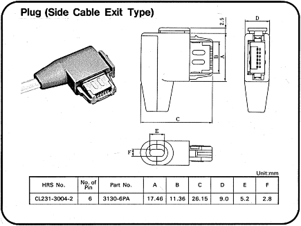
KB Plug
Identity
The P7x right angle connector is HRS #
CL231-3004-2, part # 3130A-6PA
Go to the Hirose Electric web page and look at their
catalog HERE
T. Sunagawa says:
Letter "A" after 3130 is missing. I did
same mistake and asked for 3130-6PA thus I got a brusque
reply "item not found".
The letter following.3130 stands for the
diameter of guide hole of each signal wire.
A: guide hole 0.85 ( suitable for
wire 0.75 to 0.83 )
none: guide hole 1.00 ( suitable for 0.88 to
0.98 )
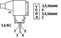
Keyboard
Connector Pinout
|
Pin
|
Vdc
|
|
2
|
+5v
|
|
3
|
Gnd
|
|
4
|
+5.0
|
|
5
|
+5.0
|
27 Nov 01- Trying to convert between the four pin
header and the common PS/2 port. My urge is to allow
installing a short female PS/2 plug to stick an external
PS/2 keyboard on. You might even want to create your own
extension cable, because finding the special extension
cable is about as likely as finding Elvis in your
kitchen.
David Beem wrote:
On second look it appears to be:
Pin 2 = +5VDC (Red on mainboard connector)
Pin 3 = Ground (Black on mainboard connector)
Pin 4 = Data (Green on mainboard connector)
Pin 5 = Clock (Yellow on mainboard connector)
Still trying to get an "M" apart for
cross-comparison.
External
Storage Device Port
The external storage
device port is the equivalent of the B drive internal
diskette port, as found in the PS/2 Model 70. This
permits attachment of externally powered devices like the
IBM 4869 External Diskette Drive Model 001 and some other
equipment manufacturers' backup devices.
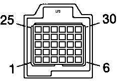
PIN I/O Signal
PIN I/O Signal
1 N/A Ground
2 I - Second
Drive Installed
3 N/A Ground
4 O
- Reduced Write Current
5 N/A Ground
6 N/A
Reserved
7 N/A Ground
8 I
- Index
9 O - Motor On 1
10 O - Drive Select 1
11 N/A Reserved
12 N/A
Reserved
13 N/A Ground
14 O
- Direction
15 N/A Ground
16 O
- Step
17 N/A Ground
18 O
- Write Data
19 N/A Ground
20 O
- Write Gate
21 N/A Ground
22 I
- Track 00
23 N/A Ground
24 I
- Write Protect
25 N/A Ground
26 I
- Read Data
27 N/A Ground
28 O
- Side 1 Select
29 N/A Ground
30 I
- Diskette Change
Note: NC means No
Connector, there is nothing in the socket.
External Storage Device Cable
P/N 23F2716 / FRU 23F3230
US4854895
A Shielded connector socket for connection with a
multipin connector plug
I think this is akin to the HDI-30 SCSI port on
Apples.
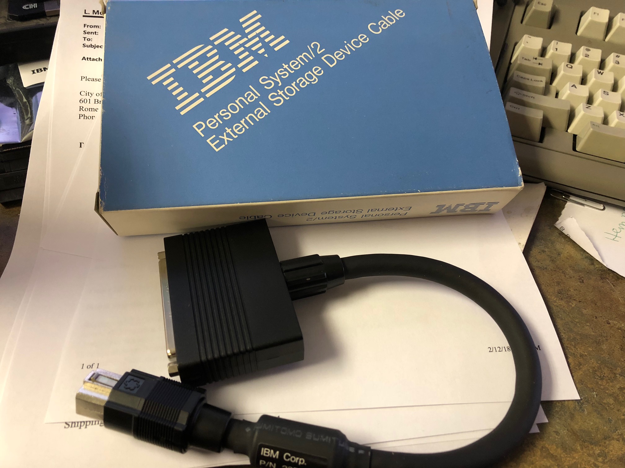
This cable attaches appropriate
external backup devices and diskette drives. It
features a Hosiden
HDI-30 connector that attaches to the external storage
device port on a P70 / P75, and at the other end is an
industry standard 37 pin D Shell connector to connect to
an externally powered device. The length of the
cable is 35.5cm (14 inches). This 30 pin port is
the equivalent of the B drive internal diskette port
(like in the PS/2 Model 70) and is reported as D:.
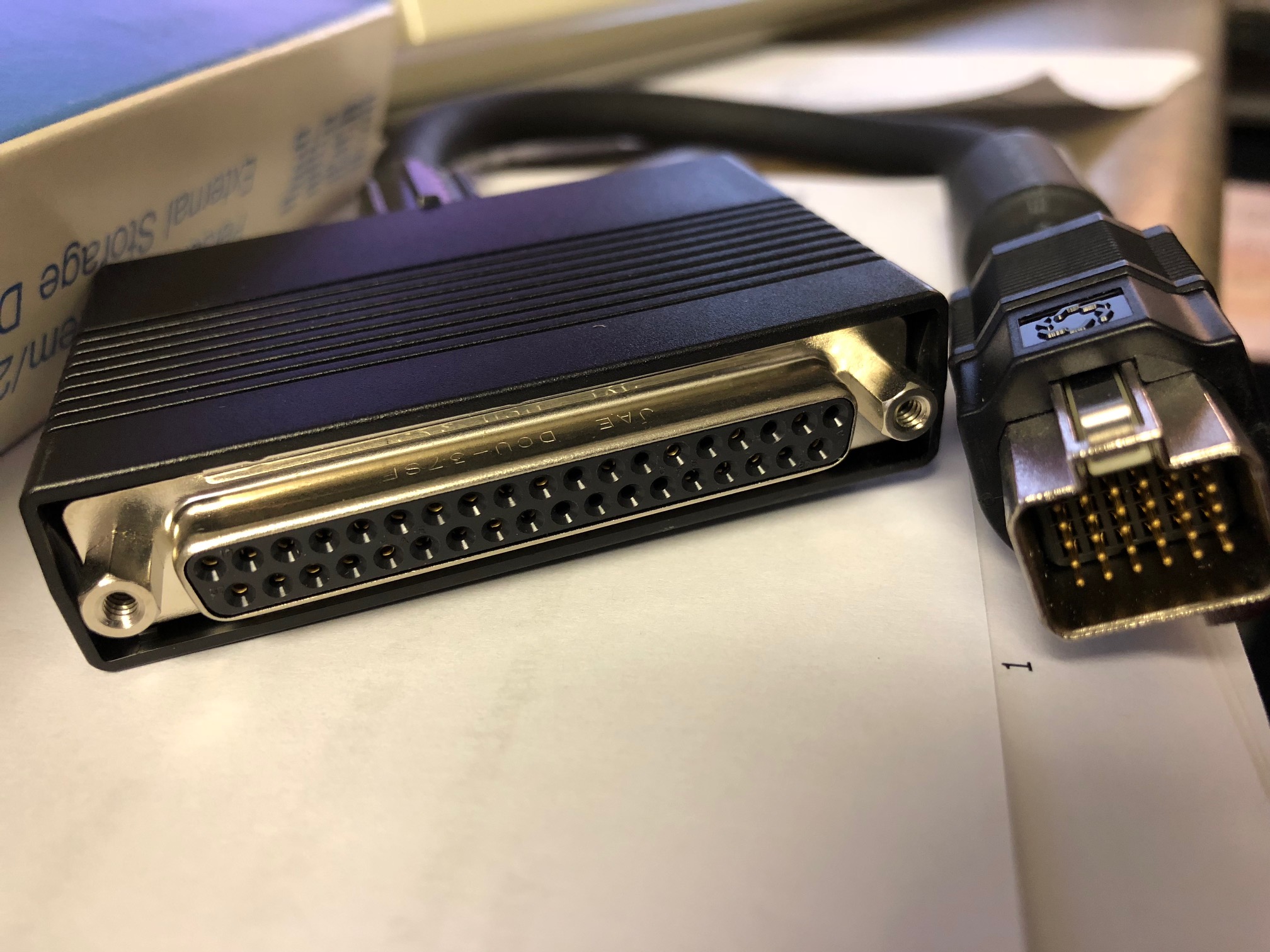
On the left is the DB37 connector that mates with the 4869
signal cable. On the right is the Hosiden HDI-30 connector
that plugs directly into the P70/P75 external storage
device port.
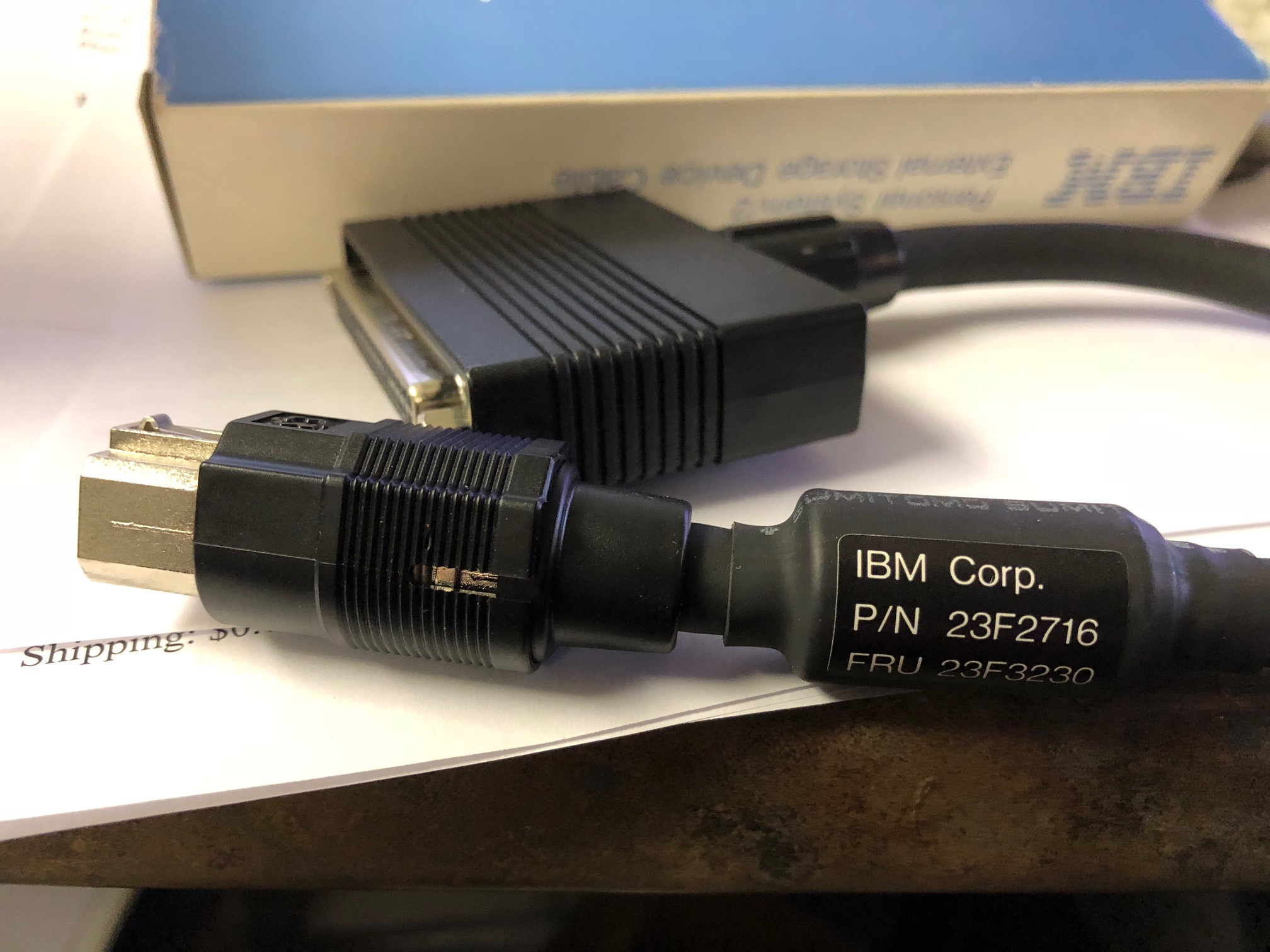
This side shot of the HDI-30 plug hints at the spring
loaded collar. To release the tension on that spring tip
at the upper left, pull the collar (using the ribs) down
toward the P70/P75 planar while pulling the cable back
from the planar.
External
Storage Device Cable Pinout
Do you want to get access to the DB37
header conductors? Unscrew the splined nut where the
cable meets the DB37 shell. Pull the nut back along the
cable, then simply pull the plastic shell after it. Now
you can see that the metal hood inside is a two part
deal. Note that there are two little latches on each
side of the hood at the front, next to the hex posts.
Use a fine bladed screwdriver or a knife to pop the hood
open, one side at a time.
Hosiden
Connector to 37 pin Connector Pinout
Now THIS is something I personally tested
with the P70 to 4869 5.25 External Floppy. Note that
this is the end of the 23F2716 cable!
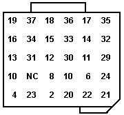
Notes:
Pin 10 on the DB37 connects to TWO pins
NC means there is no connection.
Shield to shield
External
Storage Device Cable Source
Search for 23F2716 or 23F3230 on the net.
P70 Trivia (applies to
P75 some)
The system I am using sometimes refuses to start after
power-on without any display or beep symptom. After
several power on-off eventually it starts. Any
idea???
From Peter:
Looks like a slightly buggy power supply
-or- systemboard. The PSU is a little sensible against
aging and overheating after many years, because it is a
known "dust collector". The PSU fan sits awkwardly
mounted over the PSU and only blows half (or less)
through the PSU, which causes dust particles to stay in
the PSU. I would recommend that you remove it from the
machine and give it a good blow with a compressor and
air-nozzle to get out the dust bunnies from it. Make
sure the fan is in working order.
On various occasions I saw failing mainboards. They
refused to come on - and I don't know why. They simply
died from one day to the next and could only be
replaced. Back in the "good old days" with full IBM
support and machines under warranty that was no big
problem. Today things look different. If cleaning the
power supply doesn't help - and if removing all adapters
and testing with the bare sysboard doesn't change the
misbehavior: suspect the mainboard to be damaged and
look for a replacement.
Under rare circumstances a poorly seated
card-riserboard caused trouble. Have the small two-slot
riserboard removed, clean the contacts and spray a good
amount of TV-tuner cleaner in the board connector. Let
it dry for 10 minutes and use a piece of stiff card
pushed into the connector with one edge and move it up /
down the connector. Then spray the connector once again
and let it dry for an hour. You might also repeat these
steps on the two MCA slots on the riserboard. Especially
on the slot pointing towards the top of the unit, which
collects dust when left with no card installed for a
longer time.
Some older units also developed a sort of "creeping
short" along the FDD cable where the FDD cable enters
the "flip out" FDD bay. There was an ECA for the FDD
cable from IBM for the earlier models, where FDD cables
broke, shortened DC-voltages to GND or FDD signals and
caused a dead systemboard. (Few only - IBM fixed it in
an early stage).
Another potential problem has been reported with the
memory modules. The system takes only 1 and 2MB modules
anyway, but certain 2MB modules installed on the
sysboard connectors with double sided 10 chips layout
(20 chips total - 2 x 8 data + 2 x 2 parity - 16 bigger
and 4 smaller chips) caused overload of the memory
driver lines. This usually resulted in either a
200-something memory error -or- a machine failing to
come up at all.
I take from the 16MB you'd mentioned that the upper
slot contains a memory card (the lower is too short
anyway). So you should probably check the card connector
as described further above and check if you cannot use
memory modules with lower amount of chips. Usually the
memory installed on cards causes a 200-series memory
error in first place before dumping the machine to total
darkness - but you never know.
I have several P70 in my collection and all of these
run with double-sided 2 MB chips ... but I had a customer
machine in '93 or so, which didn't. We used later
2 MB/70 ns 9-chip modules "hardware-recoded" (with
soldering) to 2 MB / 85 ns and the system worked like a
charm.
Remove Power-on Password (P75 shown, P70 similar)
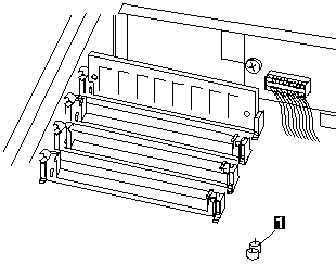
To remove an active, unknown, power-on password do the
following.
1. Power-off the computer and unplug the
power cord.
2. Remove the system-unit cover.
3. Short the two pins of JP1 together.
With the pins shorted, power-on the computer. This
erases the power-on password. Remove the short after
POST is finished.
|