|
PS/1, PS/2, and PC Memory Reference
Introduction
Visual Identification of SIMM Module
SIMM Module Presence Detection Pins
PD Bits SIMM Identification - IBM Parity Modules
PD Bits SIMM Identification - Non-Parity and ECC Modules
PD Bits SIMM Identification (IBM / Industry)
Resistor to PD Bit
SIMMulator (Socketed PD Tester, cheap!)
Introduction
Most newer IBM PS/2 machines use the 72-pin Single In-line Memory Modules
(SIMM) on either planar or memory expansion cards. Very often there are more
than one of these 72-pin connectors available and one might wish to upgrade
the memory by adding another memory module.
But the machine comes up with a error 215 and according to the error code list
it means "Check memory, it might be wrong type or wrong speed".
How can the system know that? It's pretty simple. There are 4 pins
reserved on the module, which are called "Presence Detect Pins" (PD-pins)
and which tell the planar:
- if there is a module installed
- total capacity of the module
- access-time of used memory chips
In addition there is one other special pin which is used to detect modules with
Error-Correcting Code (ECC) support.
Visual Identification of SIMM Module
Some early memory module kits are not labeled with a FRU
number. The following information provides methods of
identification.
There are four key identifiers:
- Chip size: narrow or wide
- Chip placement (horizontal, vertical, both, 1 side or 2 sides)
- Speed suffix shown on the individual chips (7=70 ns, 8=80 ns, 85=85 ns)
- Module ID resistors (R1=85 ns, R2=80 ns)
Memory-Module Kit 1A and 1B
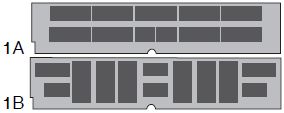
Kit 1A and 1B, show 10 or more chips mounted horizontally,
vertically or a mixed pattern. If there are chips on one
side of the board, it is 1MB. If there are chips on both
sides, it is 2MB. (A small number of 8MB kits were also
manufactured in this configuration.) The suffix on the
chip, for example, -8, -85 is important.
Memory-Module Kit 2L and 2R
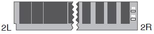
Kit 2L shows 10 wide chips with resistors across the top,
but not on the end. If there are chips on one side, it is
4MB; two sides it is 8MB.
Kit 2R shows 9 or 10 chips per side, all mounted
vertically. If there are two resistor locations on the
right end labeled R1 and R2, it is 2MB. (R1 = 85 ns, R2 =
80 ns, R1 + R2 =
100 ns.) There will either be 9 or 10 chips.
Memory-Module Kit 3
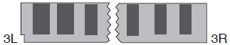
Kit 3 has 6 chips per side spaced evenly. If all the chips
are the same size, (3R) it is 1MB. If the two center chips
are smaller than the 4 outer chips, (3L) it is 4MB. These
could be any speed.
Memory-Module Kit 4A and 4B
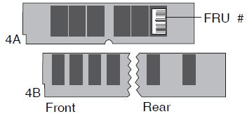
Kit 4A and 4B are both 4MB. 4A has 6 closely spaced chips
on each side. There are no resistors, and it is 85 ns
(there might be a tiny FRU number on the end chip.) 4B
shows the front and rear of another 4MB chip
configuration. There are 8 chips on the front, and 4 on
the rear.
SIMM Module Presence Detection Pins
For years, I have been living easy with the Models 90
and 95, both use 70 ns FPM SIMMs, which are fairly
common. But when faced with a 8573-P70, I was brought to
my knees by it's demands for ONLY a 2MB 85 ns SIMM. Many
of the older SIMMs are marked only with a P/N, the size
and speed are not shown. Even worse, many individual IBM
chips are marked only with IBM P/Ns... These chips lack
even a speed rating.
From the PC and PS/2 Pocket Reference Manual, Feb 1996 (edited):
The presence detect pins 67-70 tell the system
the size and speed of the IBM standard 72 pin parity
SIMMs. The pins are either not connected or connected
to ground. Using good ESD procedures and a digital Volt/ohm
meter, measure the resistance between pins 67-70 and 72
which is ground.
When you look at a SIMM, the notch is to the right. Pin
72 will be the leftmost pin (usually silk screened or part of PCB).
Note that the PD bits are binary, with LSB to the right (pin 67).
Measure resistance of pins 70, 69, 68 and 67 to ground (GND) - pin 72.
Warning!
If you use a Multimeter to check the connections on the Presence Detection
Pins, do not touch other pins than the 5 shown above! The memory module might
get damaged from the testing voltage of your multimeter. Also obey the usual
rules for handling ESD-sensitive components!
PD Bits SIMM Identification - IBM Parity Modules
Pin 48 is Not connected on Parity modules
Table sorted by presence detect (PD) information.
Pin
70 |
Pin
69 |
Pin
68 |
Pin
67 |
Size |
Speed |
Notes |
| o | o | o | o | | | Free or Invalid |
| o | o | o | X | 1 MB | 120 ns | |
| o | o | X | o | 2 MB | 120 ns | |
| o | o | X | X | 2 MB | 70 ns | |
| o | X | o | o | 8 MB | 70 ns | |
| o | X | o | X | 16 MB | 70 ns | |
| o | X | X | o | 2 MB
32 MB | 80 ns
70 ns | On older machines
IBM P/N 92F7205 or 92G7206 |
| o | X | X | X | 8 MB | 80 ns | |
| X | o | o | o | | | Reserved (*1) |
| X | o | o | X | 1 MB | 85 ns | |
| X | o | X | o | 2 MB | 85 ns | |
| X | o | X | X | 4 MB | 70 ns | |
| X | X | o | o | | | Reserved (*2) |
| X | X | o | X | 1 MB | 100 ns | Note (*3) |
| X | X | X | o | 2 MB | 100 ns | |
| X | X | X | X | 4 MB | 80 ns | Note (*4) |
o - open circuit, X - connected to GND (via bridge or 0 ohm resistor)
Notes:
- This is an accepted coding for the 8MB module used in the N51SX - see Jim Shorney's Modification and THIS for details.
- This is an accepted coding for the 4MB/80 ns module P/N 79F3988 / 79F1000 (FRU 79F1003) used on the L40SX (8543), see THIS as well.
- This is an accepted coding for the 8MB/80 ns module P/N 79F3989 (FRU 79F1004) used on the L40SX (8543), see THIS as well.
However: It must be a single-sided module with chips that have the typecode -LJP8 after the sizecode!
- This is an accepted coding for the 2MB/80 ns module P/N 79F3987 (FRU 79F1002) used on the L40SX (8543), see THIS as well.
PD Bits SIMM Identification - Non-Parity and ECC Modules
Pin 48 is to ground (GND, pin 72) on ECC modules.
Table sorted by presence detect (PD) information.
Pin
70 |
Pin
69 |
Pin
68 |
Pin
67 |
Size |
Speed |
Notes |
| o | o | o | o | | | Free or Invalid |
| o | o | o | X | 16 MB | 60 ns | Non-Parity |
| o | o | X | o | 32 MB | 60 ns | Non-Parity |
| o | o | X | X | 4 MB | 60 ns | Non-Parity |
| o | X | o | o | 8 MB
8MB | 70 ns
70 ns | Non-Parity
IBM ECC (FRU 92F0098) |
| o | X | o | X | 1 MB
16 MB
16MB | 70 ns
70 ns
70 ns | Non-Parity
Non-Parity
IBM ECC (FRU 96F9100) |
| o | X | X | o | 2 MB
32 MB | 70 ns
70 ns | Non-Parity |
| o | X | X | X | 4 MB | 70 ns | Non-Parity |
| X | o | o | o | 8 MB | 80 ns | Non-Parity |
| X | o | o | X | 1 MB
16 MB | 80 ns
80 ns | Non-Parity |
| X | o | X | o | 2 MB
32 MB | 80 ns
80 ns | Non-Parity |
| X | o | X | X | 4 MB
4MB | 80 ns
70 ns | Non-Parity
IBM ECC (FRU 92F0097) |
| X | X | o | o | 16 MB | 70 ns | IBM ECC |
| X | X | o | X | | | |
| X | X | X | o | | | |
| X | X | X | X | 8 MB | 60 ns | Non-Parity |
o - open circuit, X - connected to GND (via bridge or 0 ohm resistor)
PD Bits SIMM Identification (IBM / Industry)
Table sorted by module capacity.
Pin
70 |
Pin
69 |
Pin
68 |
Pin
67 |
PD Bits
3 2 1 0 |
SIMM Type |
| o | o | X | o | 1101 | 32MB 60 ns Industry |
| o | X | X | o | 1001 | 32MB 70 ns Industry |
| X | o | X | o | 0101 | 32MB 80 ns Industry |
| o | o | o | X | 1110 | 16MB 60 ns Industry |
| o | X | o | X | 1010 | 16MB 70 ns IBM / Industry |
| X | o | o | X | 0110 | 16MB 80 ns Industry |
| o | X | o | o | 1011 | 8MB 70 ns IBM / Industry |
| o | X | X | X | 1000 | 8MB 80 ns IBM / Industry |
| o | X | X | X | 1000 | 4MB 70 ns Industry |
| X | o | X | X | 0100 | 4MB 70 ns IBM |
| X | o | X | X | 0100 | 4MB 80 ns Industry |
| X | X | X | X | 0000 | 4MB 80 ns IBM |
| o | X | X | o | 1001 | 2MB 70 ns Industry |
| o | o | X | X | 1100 | 2MB 70 ns IBM |
| X | o | X | o | 0101 | 2MB 80 ns Industry |
| o | X | X | o | 1001 | 2MB 80 ns IBM |
| X | o | X | o | 0101 | 2MB 85 ns IBM |
| o | o | o | X | 1110 | 2MB 100 ns IBM |
| o | X | o | X | 1010 | 1MB 70 ns Industry |
| X | o | o | X | 0110 | 1MB 80 ns Industry |
| X | o | o | X | 0110 | 1MB 85 ns IBM |
| X | X | o | X | 0010 | 1MB 100 ns IBM |
| o | o | o | o | 1111 | Connector is empty |
o - open circuit, X - connected to GND (via bridge or 0 ohm resistor)
Notes:
Some Industry standard PD codes are the same as IBM's, yet differ in speed.
Some systems "mask" PD bits, ex. the 8573-P70 masks PD0 and PD1.
Pin - PD Bit - Resistor #
Note that the Resistor numbers (R1, R2...) are in reverse to the PD bit
number.
| Pin |
PD Bit |
R# |
| 70 |
PD3 |
R1 |
| 69 |
PD2 |
R2 |
| 68 |
PD1 |
R3 |
| 67 |
PD0 |
R4 |
SIMMulator
Jim Shorney says:
Whacked the end SIMM socket off of an old
Dell motherboard with a hacksaw and soldered up four LED's
with 1K current limiting resistors to pins 67-70.
Feed it 9 to 12 volts DC against pin 72, and it makes a
nice PD code reader for aSIMMilating those unidentified
memory modules into the proper baggie. No more
fumbling with an ohmmeter.
Tony Ingenoso has a safety announcement:
Sacrifice a clone mobo for the
socket. A propane torch from the rear will usually
drop 'em off pretty clean. Gotta burn through the
little attach pegs, but once that's done they drop right
off...
A pail of water is nice to have standing
by. Sometimes the boards light up pretty good and
really start stinking and billowing clouds of black
smoke. Don't want the neighbors to call the FD ;->
|