|
Source: Byte Magazine Vol 14 No 01, Jan 1989 Pages 363+
Author: Bret Glass
Editor's note:
In this issue, we inaugurate a new column
by Brett Glass, a hardware designer, programmer, and
author with some impressive credentials. Brett was one
of the architects of Texas Instruments ' TMS380 chip set
(which implements the IEEE 802.5 Token Ring local-area
network) and coauthored Living Videotext 's ThinkTank 2.
0. He founded BADGE, the Bay Area Amiga Developers '
Groupe, and is an instigator of the Hackers '
Conference, an annual get-together for the pioneers of
the microcomputer revolution. Brett holds a BSEE from
the Case Institute of Technology and an MSEE from
Stanford University. In Under the Hood, Brett will
present in-depth analyses of significant new technology,
as well as provide technical background for
understanding the material that appears elsewhere in
BYTE. We feel fortunate to have a writer of Brett's
caliber on-board, and we welcome your response to this
new column. If you 'd like to contact him personally,
see the note at the end of the column. – KS
THE TOKEN RING
The IBM Token Ring has captured more than 50 percent of
the microcomputer local-area network market and more
than 20 percent of all LAN applications worldwide. This
specification (also known as the ANSI/IEEE 802.5
standard) got a late start relative to other LAN
standards. IBM released it in late 1985, years after
Ethernet and ARCnet. Why has the Token Ring become so
popular so quickly? And what's really going on under the
hood? In this article, I'll tell the "inside story" of
the Token Ring and show why it's likely to be the
dominant LAN standard by the end of this decade.
Token Ring Fundamentals
Before I go any further, it's vital to understand where
the term Token Ring comes from. The nodes in a Token
Ring, which can be microcomputers, minicomputers,
mainframes, or other types of computer equipment, are
electrically connected to one another in a "ring"
configuration, as shown in figure 1 .
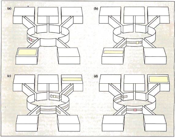
Figure 1: A
functional overview of the Token Ring. (a) The sending
station waits for a token; (b) the sending station makes
the token a frame by adding addresses and data; (c) the
receiving station copies data and sets the "copied bit";
and (d) the sending station removes the data and
generates a new token. (Figure courtesy of IBM Corp.)
Each node receives information from one of its
neighbors (its nearest active upstream neighbor, or NAUN
for short) and transmits it to the node immediately
downstream. Unless a node is transmitting its own data,
it passes on whatever information it receives from its
NAUN verbatim. Thus, any node can transmit information
to any other node by sending it through some or all of
the others. The total effect resembles an endless,
circular version of the party game Telephone, in which
players occasionally add their own information to the
circle. This is the ring part of the Token Ring.
But what is a token, and what role does it play in
making the network function? Well, as mentioned above,
each node on the ring can either transmit its own data
or retransmit the data it receives from its NAUN. As you
might expect, however, it can't do both at the same
time. Thus, if two nodes on the ring try to transmit
simultaneously, it's probable that one will "swallow"
the other's data and keep it from propagating to the
entire ring. To avoid this, the nodes take turns
transmitting, keeping track of whose turn it is to talk
by passing around an electronic "baton" called a token.
A token is a short (24-bit) message that says to the
node that receives it, "It's your turn to send data if
you want to." When a node that wants to transmit
receives a token (see figure 1a), it changes the token
into a frame, appending its address, the recipient's
address, and the data (see figure 1 b). The transmitting
node is said to be in possession of the token. No other
node can talk; each must obediently retransmit the data
as it sees it. When the frame reaches its destination
node, it is passed on (see figure 1c), with status bits
within the frame changed to indicate that it was
received. The frame continues moving along the ring
until it arrives back at the sender.
Now, it isn't very useful for the frame to go around the
ring more than once: On its initial circuit, it has
already visited every node on the ring. Therefore, the
sending node doesn't retransmit its own data. Instead,
on recognizing its own frame, it "strips" the frame from
the ring and passes a token to its nearest downstream
neighbor (see figure 1d). The cycle repeats, with each
node getting a chance to speak in turn.
This explanation is a bit simplistic (it doesn't include
the notion of priority, for instance), but it covers the
basics of the Token Ring architecture. The true
brilliance of the Token Ring design lies in the
subtleties added by IBM's scientists in Zurich and
engineers from both IBM and Texas Instruments.
The Token Ring has the ability to prioritize access to
the ring, "heal" after a cable breaks, disconnect
malfunctioning nodes, and identify the locations of
noisy connections within the network-capabilities absent
from most other popular network standards. In the
sections that follow, I'll explore some of these
features in greater depth.
The Physical Layer: Logical
Ring, Physical Star
I'll start my tour of the Token Ring with the lowest
layer of the Open Systems Interconnection reference
model: the physical layer. The first thing you'll notice
if you look at the hardware of a typical Token Ring is
that it doesn't look like a ring at all; rather, it
resembles a star (see figure 2).
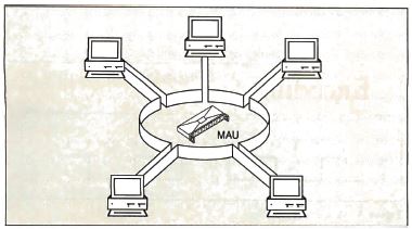
Figure 2 : At the
lowest level, the physical layer, a Token Ring looks
like a star (hence the term "star-wired ring topology ")
in which each node is connected to a wiring
concentrator, the medium access unit.
Each network node uses a single two-pair cable to
connect to a device called a wiring concentrator, or, in
Token Ring parlance, a medium access unit (MAU). One
pair is for receiving data, the other for sending data.
The star-shaped wiring topology has two advantages.
First, only one cable is needed from each station on the
network to a single, centralized location. (Telephone
systems are wired the same way. In fact, IBM suggests
that the same conduits and wiring closets be used for
both.) This design requires more cable than if you were
to simply connect successive nodes, but it makes it much
easier to add new nodes and remove old ones.
The second advantage is that it's easy to bypass an
inactive or malfunctioning node at the MAU by connecting
its upstream node directly to its downstream neighbor
(see figure 3).
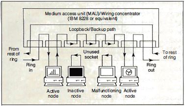
Figure 3: Signal
flow in the medium access unit. Note that any or all
nodes in the star-wired ring can be bypassed if
necessary.
When you turn a workstation off or when a node leaves
the ring because of a malfunction, current ceases to
flow in the "phantom circuit" (see figure 4) associated
with that node. A relay opens in the MAU, and the ring
reconfigures itself without the inactive machine.
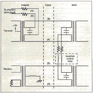
Figure 4: The
"phantom circuit " is essential to ring maintenance. If
a node is on a damaged section of the ring or if
requested by the local-area-network management program,
a node removes itself from the ring by removing its
voltage from the circuit (deactivating the phantom
circuit). The presence of too much or too little current
in the phantom circuit indicates a wiring problem.
(Figure courtesy of Texas Instruments.)
If only one MAU is in the network, the MAU configures
all the stations attached to it into a ring. If there is
more than one MAU, each links its stations into a single
ring that runs through all the MAUs.
Each node attaches to the MAU via a special
four-conductor connector. The connector is
hermaphroditic; that is, it can mate with identical
connectors. When a connector is unplugged, shorting bars
inside join the send circuit to the receive circuit,
allowing the attached device to perform loopback tests
on itself and the cable.
The connections between a node and the remainder of the
Token Ring are transformer-coupled. This limits
common-mode voltages and breaks ground loops that could
cause harmful interference on the ring.
Longer Distances
In a bus-based network, like ARCnet and Ethernet, each
network node must be able to be heard by all the others,
thereby limiting the total size of the network to the
distance that a single adapter' s signal can reach. But
since each node on the Token Ring needs to send a signal
only as far as the next node, a Token Ring can be much
larger. A Token Ring node can be up to 300 meters away
from its MAU, while an Ethernet (without repeaters) can
span 500 meters maximum.
Encoding (Spreads
across 366 and 367)
The Token Ring uses differential Manchester encoding to
transmit bits on the ring. Manchester encoding schemes
are "self-clocking"-they attempt to guarantee enough
up-and down transitions in the incoming signal so that
it's easy to predict when the next transition is going
to occur.
Manchester and differential Manchester encoding require
that there be a transition in the middle of each bit. In
Manchester encoding (see figure A), the direction of the
midbit transition determines whether the bit was a 0
(high-to-low transition) or a 1 (low-to-high
transition).
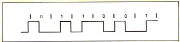
Figure A: Manchester
encoding.
In differential Manchester encoding (see figure B), the
bit is a 0 if a transition occurs at the beginning of
the bit time and a 1 if there is no transition at the
beginning. Differential Manchester encoding was chosen
for the Token Ring because it is polarity-independent,
making the Token Ring easier to wire. The transmit and
receive pairs and the transformers that drive them can
be connected without keeping track of "positive" and
"negative" leads.
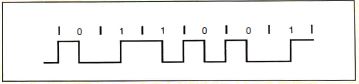
Figure B:
Differential Manchester encoding.
The Token Ring also uses Manchester code violations -
occasional bits without transitions in the middle- to
make delimiters completely unambiguous (see figure C).
Besides 0 and 1, the Token Ring standard defines two
"nondata" bits: J, a 1 bit without the middle
transition, and K, a 0 bit without the middle
transition.

Figure C: Manchester
code violations.
When it's not sending data, a node "idles"-usually by
transmitting 0 bits continuously. This provides the
downstream node with a large number of transitions with
which it can synchronize its clocking circuits. In no
case should a station ever transmit more than 5
consecutive half-bits without a transition. If a node
does not see a transition on its input after 5 half-bit
times, a "BURSTS Error" has taken place. The node
assumes that a serious ring problem has occurred and
attempts to reestablish contact with its neighbors.
When the ring is idle, the stations on the ring
continuously relay a token. A token consists of 3 bytes: a
start delimiter, an access control field, and an end
delimiter (see figure D). The most-significant bit of each
byte is transmitted first; this is the reverse of
Ethernet, RS-232C, and most other serial communications
standards. The start delimiter and end delimiter contain
Manchester code violations (Js and Ks); this guarantees
that they will not be mistaken for ordinary data bytes.
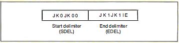
Figure D: The abort
delimiter consists of a start delimiter and an end
delimiter
together.
When a node that wants to transmit receives a token, it
changes the token into a frame, appending its address, the
recipient's address, and the data (see figure E). The
frame also contains a redundancy code, and a status byte.
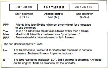
Figure E: Token
format.
In the event that a node needs to abort a transmission in
the middle, it sends an abort delimiter sequence, which
consists of the start delimiter and the end delimiter
together (see figure F).
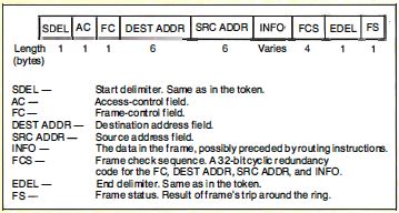
Figure F: Frame
format.
The MAC Sublayer
Let ' s examine the signals the Token Ring's physical
medium carries and the techniques used to arbitrate access
to the ring: the media access (MAC) sublayer. Data is
transmitted on the ring using differential Manchester
encoding (see the text box "Encoding" above) , typically
at 4 megabits per second (IEEE will release a 16-Mbps
Token Ring standard soon). When the ring is idle, the
stations on the ring continuously relay a token (sometimes
called a "free token") to one another.
When a node that wishes to transmit receives a token, it
examines the priority bits to make sure its message has a
priority at least as large as that of the token. If it
does, it converts the token into a frame. Occasionally, a
node will "decide" to abort a transmission in the middle.
To do so, it sends an abort delimiter sequence, which
consists of the start delimiter and the end delimiter
together.
Addressing on the Token Ring
The IEEE 802.5 specification allows address sizes on the
Token Ring. Besides a 6-byte address (the same length as
in other IEEE standards), "short" 2-byte addresses are
available for small networks.
The source address and destination address fields of a
frame can do more than identify a• single sender and
recipient for the frame. The most significant bit of a
source address is the routing information indicator, used
when two or more rings are interconnected by nodes called
bridges. When this bit is a 1, it indicates that the frame
will specify not only the address of the destination node,
but also a route to it-possibly spanning several rings.
This technique is called source routing. Because the route
is already worked out, the job of a bridge is simple. All
it needs to do is follow the sender's routing
instructions, which are tacked onto the beginning of the
INFO field.
Destination addresses also have bits and bit patterns with
special significance. It's possible to earmark frames for
a server, a group of nodes, or all nodes (a broadcast
address).
Functional addressing is a powerful feature built into
every Token Ring adapter. By sending a frame to a
functional address, a node can use network services-like a
parameter server, an error monitor, or a network manager
without knowing the address of the nodes that provide
those services to the ring.
The Active Monitor
So far, most of the features I've looked at assume that
the ring is up and running properly. But what if something
goes wrong? When you first bring the ring up, or when any
malfunction requires reconfiguration, the nodes on the
ring test their equipment and send signals to one another
to identify their NAUNs.
The nodes select one node (normally the active node with
the numerically largest address) as the active monitor.
This node is designated to perform special "watchdog"
functions. The process by which neighbors are identified
and the active monitor is chosen is called "beaconing."
Once the active monitor has been chosen, it clears the
ring and issues a token to restart normal ring operation.
The most basic function of the active monitor is to
provide a clocking signal for the Token Ring. All other
stations on the ring "listen" to this signal and
synchronize with it. (The active monitor uses its own
crystal to clock the data it transmits.)
The active monitor's next responsibility is to ensure that
a token is circulating on the ring. First, the active
monitor has to make sure that the token "fits" on the ring
by introducing a 24-bit shift register into the ring.
(Each node is designed to incur a minimal delay, typically
1 to 2 bit times. The wiring of the ring may not have 24
bits of delay all by itself. If the signal travels on the
ring at two-thirds the speed of light, the ring needs to
be 2/3 X 3 X 10(8) meters/second X 24 bits / [ 4 X 10(6)
bits/ second] long, or at least 1200 meters long, for the
wiring to delay the signal 24 bit times.)
The active monitor also watches for "lost tokens. " If it
does not see a frame or a token go by within any
10-millisecond period, it clears the ring and starts a new
token circulating. These actions keep the token from being
irretrievably lost if a station fails to retransmit it.
The active monitor checks for frames and priority tokens
(tokens with a priority greater than 0) that circulate
around the ring more than once. It does this by checking
the setting of the monitor bit in the access control (AC)
field of each token or frame it sees. If the active
monitor receives a priority token or frame with the
monitor bit cleared, it sets the bit as it passes on the
information. If the token or frame returns when it should
not, the active monitor will discover that the monitor bit
is already set to 1, and it will immediately purge the
ring of data and restart the token-passing process.
Finally, the active monitor must "re-assure" the other
stations on the ring that it is present and working. To do
this, it broadcasts an active-monitor-present frame to the
rest of the ring. If an AMP frame fails to circulate every
so often, another station (the standby monitor) takes over
the active monitor's job.
A Matter of Priority
On most other LANs, all nodes compete on an equal basis
for use of the physical medium. For instance, there 's no
way for an Ethernet station to say, "I have a very
important message to send; please let me go next! " As an
Ethernet gets crowded with traffic , it becomes likely
that collisions, or just bad luck, will cause a delay of
high-priority messages. We say that networks like the
Ethernet are not "deterministic" -there 's no upper bound
on the amount of time it will take a node to gain access.
In some situations, like sensitive control application s,
the delays can be disastrous.
Some networks are deterministic but lack priority
structures. ARCnet, which is a token-passing bus network,
guarantees that each node can talk in turn, but the turns
are always distributed evenly. There 's no provision for
getting an urgent message to its destination faster.
The Token Ring, however, has a unique scheme that provides
for multiple priority levels and egalitarian, round-robin
access on each level. The key to this scheme is the AC
field present in each token or frame, which carries
priority information and accepts "reservations" for the
next use of the token.
After a station transmits a frame, it examines the AC
field when the frame returns. If the reservation bits of
the AC field contain a number greater than the priority
level on which the station is currently transmitting, it
means that one or more nodes wish to transmit at the
higher priority as soon as possible. The sender emits a
token with the higher priority. Since a station can use
only a token that has a priority less than or equal to the
priority of the frame that it wants to transmit, the token
travels the ring until it reaches the station that
urgently needs it.
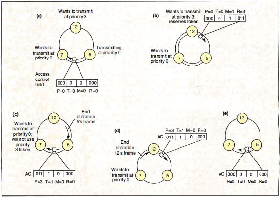
Figure 5: Placing a
reservation. (a) Station 5 is transmitting a frame to
station 7 on the ring. Normally, station 7 would be the
next node to get the token, even though station 12 had a
higher-priority frame to transmit. (b) Station 12 sees
that the reservation field of the frame is less than 3 and
places a 3 there. The frame continues back to station 5,
which absorbs the frame and emits a token. (c) The token
emitted by station 5 had priority 3, so station 7 does not
use it. The token continues on to station 12, which uses
the token to transmit a frame. (d) When station 12 has
finished transmitting, it releases a token, still at
priority level 3. (e) Station 5 receives a token at
priority level 3 and "remembers " that it was the one to
raise the priority of the token. It therefore restores the
priority to 0 so that station 7 will have a chance to
transmit.
Figure 5 shows an example of the Token Ring's reservation
system at work. In the simple three-node ring shown, with
nodes at 5, 7, and 12 o'clock, station 5 is transmitting.
Station 7 would normally use the token next, followed by
station 12. But since station 12 has an urgent message to
transmit, it changes the reservation field at the
beginning of station 5's frame. Station 5 honors the
reservation, emitting a priority token that station 7
cannot use.
Once station 12 is through transmitting and the frame has
completed its circle, station 12 strips its frame from the
ring and passes the priority token onward. The priority
token completes its loop (being used in turn by any other
nodes having urgent messages) until it returns back to
station 5 (which originated the priority token) . Station
5 then demotes the token to a lower priority and gives
station 7 its turn.
The Token Ring priority system has some especially nice
properties. First, the priority of the token is always
restored by the same node that raised it. Thus, a request
for a high-priority token does not destroy the round-robin
scheme on a lower level.
Second, it can recursively nest on all eight possible
priority levels. Suppose, for instance, that station 5,
from the previous example, had placed a reservation for
priority level 6 while station 12 was transmitting (see
figure 6) . Station 12 would elevate the priority of the
token exactly as station 5 did and allow it to circulate.
Station 12 would then restore the priority to 3. Station
5, in turn, would restore the priority of the token to 0
again.
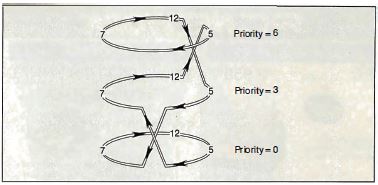
Figure 6: If, in
figure 5, station 5 had placed a reservation for priority
level 6 while station 12 was transmitting, station 12
would elevate the priority of the token, allow it to
circulate, then restore the priority to 3. Station 5, in
turn, would restore the priority of the token to 0 again.
You can now see why the active monitor watches for
recirculating priority tokens. Since each station that
raises the priority of a token is responsible for lowering
it again, a recirculating priority token indicates that a
node has malfunctioned.
This scenario demonstrates only two levels of nested
priority, not the most complicated (seven-level) case. But
no matter how deeply priorities are nested, the result is
the same: Round-robin order is maintained on each level,
and the next node to transmit is always the one with the
highest priority. These orderly and evenhanded procedures
for selecting the next node to transmit pay off especially
well under heavy loads. When many nodes contend for use of
the network, a 4-Mbps Token Ring can perform nearly as
well as a 10-Mbps Ethernet, while a 16-Mbps Token Ring can
provide more than double the throughput.
I've already discussed one way in which faulty equipment
can be removed from the Token Ring: the phantom circuit.
Nodes that don't pass a thorough self test verifying that
they can communicate properly with the rest of the ring
remove themselves from the network. A more subtle feature,
however, is the Token Ring's ability to localize
intermittent faults and noisy links.
As you may recall, each node examines every token or frame
it sees and sets the error-detected indicator if it
detects any errors. The error-tracking process does not
stop there. Each node maintains an internal count of how
many times it set the EDI. Network management software can
access this counter. If there is an intermittent or noisy
path in a Token Ring network, the system can always track
it down to a specific stretch of cable (a "failure
domain") by determining which node is just downstream.
In certain cases, it's also possible to bypass a run of
cable that has been completely destroyed. Look at figure 7
and notice the backup path. When two or more MAUs are
connected in a ring, this path goes unused, because the
ring goes in one end of each MAU and out the other.
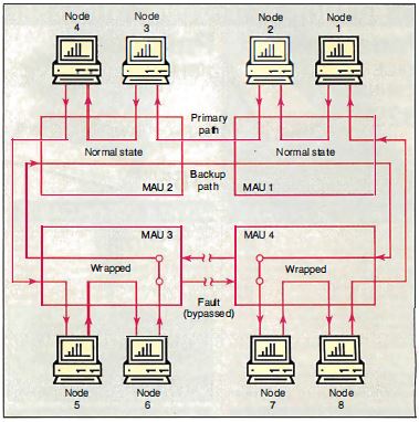
Figure 7: The Token
Ring can reconfigure itself to bypass shorts or breaks
in a cable. In this diagram, the ring continues to
function despite a cable break between MAU 3 and MAU 4.
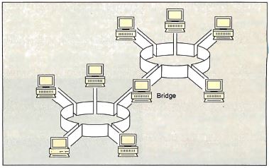
Figure 8: A Token
Ring bridge, a node that is on two rings at the same
time and can pass frames from one ring to the other.
(Figure courtesy of IBM Corp.)
But suppose that, for some reason, one of the cables
connecting the MAUs into a ring fails. To get the ring
up and running again, all you need to do is to remove
the failed cable from both MAUs, allowing the backup
path, which runs through all the MAUs, to complete the
loop. Voila! The ring is up and running again. If the
MAU is an "intelligent wiring center" (IBM doesn't make
one, but Proteon and other vendors do), you may not even
need to remove the cable. The network management
software is able to reroute the ring without any human
intervention whatsoever.
Bridges and Backbones
A bridge is a node that is on two rings at the same time
and is able to pass frames from one ring to the other.
Figure 8 shows a simple bridge. Figure 9 shows multiple
rings bridged to a backbone ring. In large
installations, a backbone ring connects many rings to
each other. It consists of a series of bridges, each
connecting a local ring to the backbone.
NetBIOS and the Token Ring
Originally, the IBM NetBIOS (see my article
"Understanding NetBIOS " on page 301) had to handle many
of the same functions that the Token Ring provides. The
firmware present on most Token Ring adapters (the LLC
sublayer) orders packets and ensures their delivery.
Therefore, the NetBIOS API (Application Program
Interface) is provided by a NetBIOS emulator.
Despite the extra layer of interface, the Token Ring
card usually performs better than the original IBM PC
Network.
Token Ring Chip Sets
As of this writing, three chip sets implement the Token
Ring architecture. The two produced by IBM and
UngermannBass are proprietary and not available to the
general public. The third, the Texas Instruments TMS380,
is available to all who wish to build an interface to
the Token Ring.
The TMS380 chip set consists of five parts. The two Ring
Interface chips (TMS38051/52) contain the analog
components to interface to the ring. The Protocol
Handler (TMS38020/21) manages the bit-level ring
protocols.
The Communications Processor (TMS38010) contains a
16-bit microprocessor and 2.75 K bytes of RAM; it
executes firmware (co-developed by Texas Instruments and
IBM) from a ROM in the Protocol Handler. The System
Interface (TMS38030) connects the whole package to a
Motorola or an Intel microprocessor bus.
We can expect the chip set to shrink to two chips soon,
and to a single chip eventually. IBM uses its
proprietary chip set on the PC and PS/2 Token Ring
cards, but it uses the Texas Instruments chip set on the
Token Ring adapter for the RT. This is a good indication
that the two implementations are compatible.
As this article went to press, the IEEE 802.5 committee
was finalizing the text of the standard for the 16-Mbps
Token Ring, and IBM released new dual-speed (4/16-Mbps)
Token Ring adapters. Incorporated in the new boards is
Early Token Release, which lets more than one frame (but
only one free token) occupy the ring at one time. A
proposal that may be adopted soon describes dual rings
that rotate in opposite directions and merge to form a
single ring if a cable fails. This feature is supported
by Proteon but not by IBM.
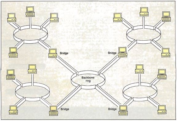
Figure 9: A backbone
ring consists of a series of bridges in a ring, each
connecting a peripheral ring to the backbone.
An Animated Demonstration
This article has covered much of what there is to know
about the Token Ring. For those readers who want to
learn more or who want a graphical explanation, I've
saved a fun and interesting surprise for last. The
marketing folk at IBM's Research Triangle Park facility
have developed a freely redistributable animated
presentation on the Token Ring that will run on any IBM
PC with a CGA.
First, download the file TOKNDEMO.ARC from the BIX
listings file area "FROMBYTE88." (Warning: It's almost
180K bytes long.) Use PKXARC to unpack it onto a
formatted floppy disk. Make the floppy disk the logged
drive and type AUTOEXEC. You'll see a wonderful
interactive demonstration of tokens running around
rings, changing into frames with messages, shifting
priorities, and vaporizing mysteriously. (Watch out for
the mischievous starship Enterprise!) The demonstration
software uses a special technique to produce up to 20
simultaneous colors on an IBM CGA and isn't guaranteed
to work with all EGA or VGA implementations. However,
you should still be able to follow the demonstration
(perhaps sans some of the brilliant colors) on almost
any compatible system. Have fun! •
Many thanks to Leon Adams and Leslie Price of Texas
Instruments for providing vital materials for this
article. Thanks also to IBM for use of diagrams and the
Token Ring interactive demonstration.
BIBLIOGRAPHY
LAN Primer (RTC Support Tool). Dallas: Texas
Instruments, 1987.
The IBM Token-Ring Network Decision, 2nd ed. Armonk, NY:
IBM, 1986.
TMS380 Adapter Chipset User 's Guide. Dallas: Texas
Instruments, 1986.
TMS380 Adapter Chipset User 's Guide Supplement. Dallas:
Texas Instruments, 1987.
|