|
193-342 IBM 9507 Color Display
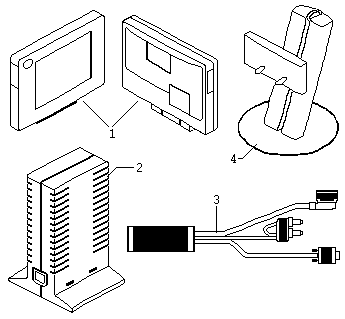
9507 Components
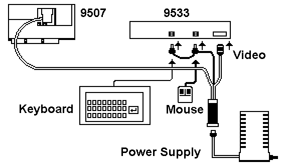
9507 Cable
9507 DC Plug
User Adjustable Effects
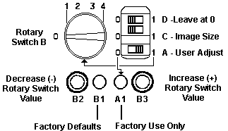
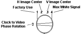
9507 Control Settings
9507 Components

© Copyright IBM Corp.
Index
FRU P/N
1 Display Panel 39G5742
2 Power-supply unit 39G2280
3 Cable-concentrator 39G5727
4 Lift/tilt/swivel 39G2279
stand
9507 Cable

Wow, this little beauty is made of unobtanium, half life
of youllneverseeit. The Keyboard and Mouse connect through pass-through
connectors to the system.
9507 DC Plug
Peter Wendt spake:
Yes I pulled it from under the workbench and I even took
it apart, which is a bit tricky due to the *security hex* (not TORX) screws.
But I did it.
The DC output ratings printed on it are 12V, 1.3A / 5V, 1.4A, AC input
is rated 100 - 240V, 0.6 - 0.3A, 50/60 Hz (worldwide useable).
4 pin plug of unfamiliar shape, ressembles Mini-DIN for keyboard / mouse,
but with fewer but thicker pins 4 wires: red, yellow, blue and black.
Looking *into* the DC plug from the open pin side the assignment is
as follows:
---\=/---
Red = + 5V
Red | o o |
Yellow Yellow = +12V
|
|
Black = GND
Black \ o o /
Blue Blue = Current Sense (?)
\_---_/
That blue wire is a bit estranging. There is a difference of 0.6V (monitor
off) and 0.4V (monitor on) between that and GND. The power unit has two
LED's: amber and green. Amber is "Power", comes on when AC is applied,
green is "Activity", comes on when the monitor is connected and the system
is not in power save mode.
Height: 225mm, Width: 120mm, Depth: 60mm (body), 130mm (with base).
Black and weighs about 300g probably. All-plastic case with 3 catches at
the front to accommodate the cable / converter box for the 9507 (that box,
which detects the mouse and keyboard signals and turns on / off the screen).
DC cable length: about 1 meter, non-detachable.
Hope it makes it clear. Do you want / need photos also ? Else I stuff
it back down again.
User
Adjustable Effects
The two effects which are easiest to identify and adjust
are Vertically and Hoizontally off-center image. Other effects are more
subtle. In particular, liquid-crystal displays driven by an analog source
exhibit certain optical effects which may, in some applications and workplace
environments, over a period of time become distracting.
They are liable to be perceived by the user as:
Slight tremors up or down the vertical
lines of tables, boxes and text characters, the tremors may seem to be
moving or stationary. A faint, linear, horizontal, background quiver in
areas of solid color. Slight ghost-imaging or smearing of horizontal lines.
They indicate that the optimum internal settings of the display panel installed
by the factory need to be fine-tuned to the application or workplace lighting
conditions.
However there are some colors which liquid- crystal displays cannot
represent easily when driven by an analog source. The display creates these
colors by switching alternate pels on and off, or half off. If you cannot
get an acceptable rendering of a particular color, the user may have to
choose another.
From Peter
It really runs best in 16-colors VGA mode. Greyscales
cause a lot "turbulences" on the display - running horizontal lines and
such. Don't forget that the display is "analog attached": the signal from
the video card is converted into analog signals and back to digital in
the monitor. No comparison with modern large scale TFT LCDs, which have
digital direct drive without the DA-AD conversion stage.
Non adjustable Effects
Liquid-crystal displays are liable to experience condition refereed
to as failed sub-pixels. The user becomes aware of them as dark or bright
pinpoints which appear, in every application, at the same place, or places,
on the screen.
You cannot adjust these pinpoints or remove them. The design specification
for the IBM 9507 Color Display allows a small number of failed pixels,
comprising a mix of on-pels and off-pels.
9507
Color Display Adjustment Settings
Only attempt to fine tuning when stable temperature conditions
have been established for the IBM 9507 Color Display. This will generally
mean that the display panel has been running for at least 20 minutes.

Leave Switch D at 0 and Switch A at 1.
D Factory use only (set at position 0).
C Position 0 - automatic installation at factory of a full-screen
image.
Position 1 - to expand or compress the image.
A Position 0 - factory use only.
Position 1 - to enable user adjustment.
A1 Factory use only
Rotary Switch B Functions

Use B2 to decrease value (-).
Use B3 to increase value (+).
Use B1 to set ALL functions back to factory defaults.
For each function selected
with the rotary switch B pushbuttons B2 and B3 are used to effect a shift,
in opposite directions, from the current internal settings. The shift in
settings affects the characters on the screen. One press causes a one-increment
shift in the value of setting.
Note: The recessed pushbutton
B1 is a RESET pushbutton. When it is
pressed, the settings installed at the factory are re-installed. You may
press pushbutton B1 (for example, with the tip of a pen) at any time during
fine tuning at any function selected with rotary switch B.
|